Acer Altos RM900 User manual

Acer Altos RM900
Installation Guide
1
1Getting Started
Unpack the rack and check the packing list that came with it. Make
sure that you have all components.
The unit of measurement used in this
document is "U" (1U = 1.75 inches or 44.45
mm). The total sum of the heights of all
components in the rack measured in "U"
cannot exceed the height of the rack.
1.1 Standard Components
The standard rack consists of the following:
•Removable vented front and rear doors
•Removable side panels
•Stabilizing feet
•Leveling feet
•Casters
•Cable management brackets
•M6 washer-face screws
•M6 cage nuts
2
1.2 Optional Components
•Acer Altos 1100, 11000, 12000, and 21000 server rackmount kit
•Fixed monitor shelf
•One 19-inch keyboard/touchpad with sliding shelf
•4-port keyboard/mouse/monitor switch box
•Blanking panel kit (one 1U, one 2U, and one 3U)
•Acer Altos storage subsystem
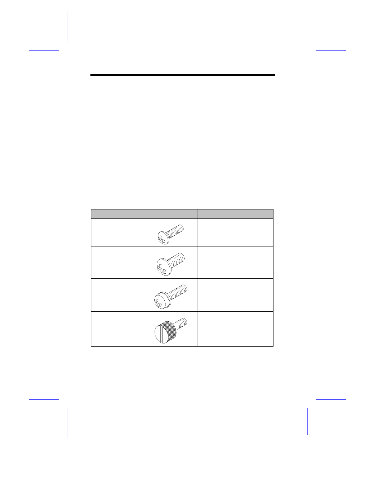
1.3 Screw Types Used
The following screws are used in the assembly of the Acer Altos
RM900 and other rack-mountable components:
Screw Type Figure Usage
M4 metal screw Securing the component
rail to the mounting rail.
See section 8.1
M5 metal screw Securing the system
components and the
mounting brackets to the
rack
M6 washer-face
metal screw
Securing the system
components to the rack
M6 thumbscrew Securing the server
system to the rack (for
Acer Altos 1100 server)

3
Screw Type Figure Usage
#6-32 screw Installing the front panel to
the server system (for
Acer Altos 11000, 12000,
and 21000 server)
#6-32
thumbscrew
Securing the server and
front panel to the rack (for
Acer Altos 11000, 12000,
and 21000 server)
M5 metal tapping
screw
Securing the cable
bracket to the rack (comes
with the cable bracket
package)
Cage Nut Supports the M6 metal
screws for securing
system components to the
rack
4
2Features
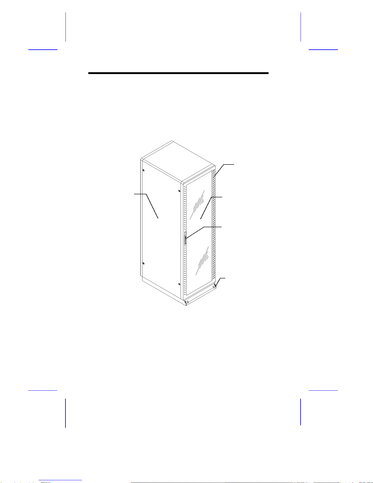
2.1 Front View
The following figure shows the front view of the Acer Altos RM900:
Figure 1 The Acer Altos RM900 (42U Rack) - Front View
Vents
Front Door
Side Panel
Handle with Lock
Stand and
Stabilizing Foot

5
2.2 Rear View
The following figure shows the rear view of the Acer Altos RM900:
Figure 2 The Acer Altos RM900 (42U Rack) - Rear View
Rear door
Handle
Leveling foot
(beside caster)
Fan

6
2.3 Inside Components
The following figure shows the different components that can be
installed in the Acer Altos RM900:
Figure 3 A Typical Acer Altos RM900 Enclosure
Monitor
Blanking panelBlanking panel
Storage subsystems
Switchbox
Keyboard/touchpad
with sliding shelf
Server
Server
UPS
7
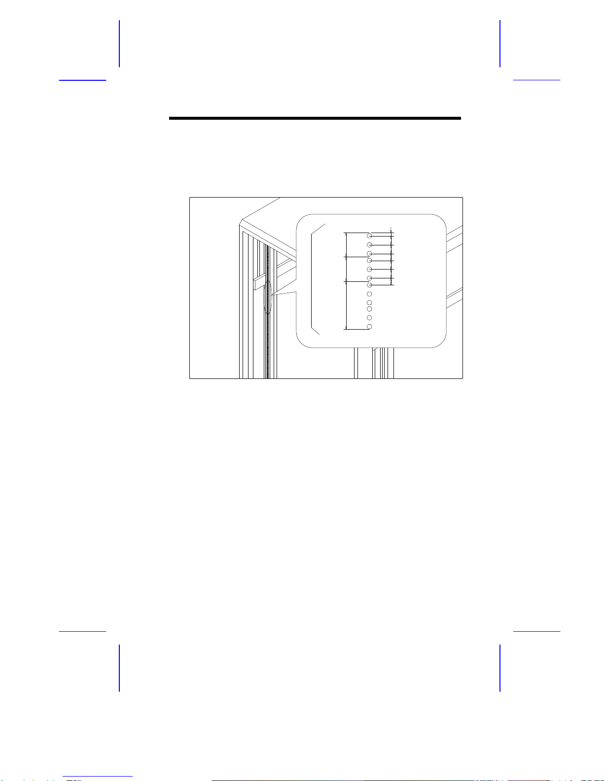
2.4 Vertical Mounting Hole Pattern
The four vertical rails of the Acer Altos RM900 contain square
mounting holes arranged in a manner shown in this figure:
Figure 4 Vertical Square Mounting Hole Spacing
The distance from the center of two holes with closer spacing to the
center of the next pair is equivalent to 1U.
When installing components, you must start your measurement from
the center of the two holes with closer spacing. Otherwise, the screw
holes on the component may not match with those on the rack.
1U
1U
2U
0.25”
0.625”
0.625
0.5”
0.625”
0.625”
0.5”
8
3Positioning the Rack
The rack comes with casters to help you move it easily from one
place to another.
To position the rack:
1. Allow the following minimum clearances:
For operation: Leave at least 46 cm (1.5 ft) of clearance in front
of the rack and 31 cm (1 ft) behind the rack to allow adequate
airflow.
For servicing: Allow 61 cm (2 ft) of space behind the rack and
165 cm (65 inches) in front of the rack.
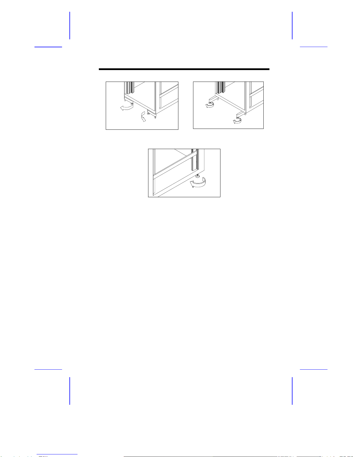
2. After you have positioned the rack, locate the two stabilizing feet
and the two leveling feet placed just next to each caster. These
feet are used for support to ensure that the rack is stable and to
compensate for uneven floors when leveling the rack. See step
2 of Figure 5.
3. Pull out the two stabilizing feet. See step 3 of Figure 5.
4. Rotate each foot to adjust it. Continue adjusting the feet until the
rack is level. See step 4 of Figure 5.
Make sure the rack is stable.
9
Step 2 Step 3
Step 4
Figure 5 Adjusting the Rack Feet

10
4Opening and Closing the Door
The rack has one front door and one rear door. Both doors are
vented and can be opened easily.
To open the rack's front or rear door:
1. Slide the keylock cover as far as it will go, press the keylock
button to automatically release the handle. If the door is locked,
unlock it using the key.
2. Rotate the handle 90 degrees counter-clockwise until the latch
releases, and then pull open the door.
Step 1 Step 2
Figure 6 Opening the Rack Door
To close the rack's front or rear door:
1. Shut the door and rotate the handle clockwise to its original
position.
2. Push the handle until it clicks.
Table of contents
Other Acer Server manuals

Acer
Acer AB2x280 F1 User manual

Acer
Acer RC111 User manual

Acer
Acer AT350 F1 Series User manual

Acer
Acer AR160 F1 Series User manual

Acer
Acer Altos easyStore M2 User manual

Acer
Acer Altos G300 User manual

Acer
Acer Altos R920 Series User manual

Acer
Acer AT115 F1 User manual

Acer
Acer AcerAltos 21000 Parts list manual

Acer
Acer Altos R480 F4 User manual

Acer
Acer 700id User manual

Acer
Acer R5250-Q2000 - Altos - 2 GB RAM User manual

Acer
Acer M9N System User manual

Acer
Acer Altos R300 User manual

Acer
Acer R310-U-P3200 - Altos - R310 User manual

Acer
Acer Veriton N2110G User manual

Acer
Acer AB460 F1 User manual

Acer
Acer AC100 User manual

Acer
Acer AR360 F1 Series User manual

Acer
Acer Altos G310 MK2 Series User manual


