aci A/PS24 User manual

Automation Components, Inc.
2305 Pleasant View Road | Middleton, WI 53562
Phone: 1-888-967-5224 | Website: workaci.com
Page 1
A/PS24 (POWER SUPPLY)
Installation & Operation Instructions Phone: 1-888-967-5224
Website: workaci.com
GENERAL INFORMATION
The A/PS24 adjustable power supply is a low
cost, dependable external power supply. This
unit will accept an input of up to 26 VAC or 36
VDC, and provides an adjustable 1.5 to 26 VDC
output. Field voltage adjustment is done by
adjusting a potentiometer using a flat-head
screwdriver. The A/PS24 is setup for Half-wave
rectification from factory, but can be set to
Full-wave rectification via jumpers.
MOUNTING
PS24 is supplied with a snap track for
mounting. The circuit board may be mounted
in any position. In equipment / electrical
compartments, mounting upside down at top
of the enclosure is not recommended as heat
build-up could be a problem when running
higher current loads.
Use only fingers to remove board from snap
track. Slide out of snap track or push against
side of snap track and lift that side of the
circuit board to remove. Do not flex board or
use tools.
WIRING INSTRUCTIONS
PRECAUTIONS
• Remove power before wiring. Never connect or disconnect wiring with power applied.
• All wiring must comply with local and National Electric Codes.
• It is recommended you use an isolated UL-listed class 2 transformer when powering the unit
with 24 VAC. Failure to wire the devices with the correct polarity when sharing transformers may
result in damage to any device powered by the shared transformer.
• In applications where a Pilot Duty or remote relay is required, the A/DO008 transorb can be
placed across the coil of the relay to snub electrical spikes when the relays are de-energized. An
external transorb may not be required if the relay and PS24 power supply is mounted within the
same control panel.
FIGURE 1: DIMENSIONS
PCB Board
Snap
Track
2.88”(73.2mm)
0.70”
(17.78mm)
2.05”
(52.07mm)
3.10”(78.74mm)
Fuse
24 VAC
VDC
Output Selection Jumpers
V-OUT
Adjustment
Power
Indicator
(LED)
+
-
+
-
Version 4.0
I0000824

Automation Components, Inc.
2305 Pleasant View Road | Middleton, WI 53562
Phone: 1-888-967-5224 | Website: workaci.com
Page 2
Version 4.0
I0000824
WIRING INSTRUCTIONS (Continued)
1) Supply Voltage - The input voltage to the A/PS24 should come from an isolated 24 VAC
transformer or a 30 to 36 VDC power supply. Connect this to the + 24 VAC – Terminal blocks.
Note: A grounded DC (-) terminal and a grounded 24 VAC Input transformer will blow the unit’s fuse
in the Full-Wave mode. Also, in half-wave mode, the 24 VAC connections are POLARITY SENSITIVE.
Be sure to insure that all 24 VAC minus (-) terminals are connected to the the same lead on the 24
VAC transformer.
Without any load attached, the PS24 uses 1.5 VA
when powered. Be sure to size the 120 VAC to 24
VAC transformer to handle the power (VA)
required by both the PS24 and the load
connected to the PS24. The PS24 is 65% efficient
with a 24 VDC output voltage setting.
Derate the transformer VA to x%. Determine
output power required from the equation
(voltage output x current draw from load) = VA
load. Example: (24 VDC * 0.2A) = 4.8 VA load.
Determine transformer power from the equation
(output VA / efficiency) = VA transformer (or
similar). Example: (4.8 VA / 0.65) = 7.4 VA
transformer.
2) Output Connections – Connect your load to –
VDC + Terminal Blocks. Be mindful of polarity.
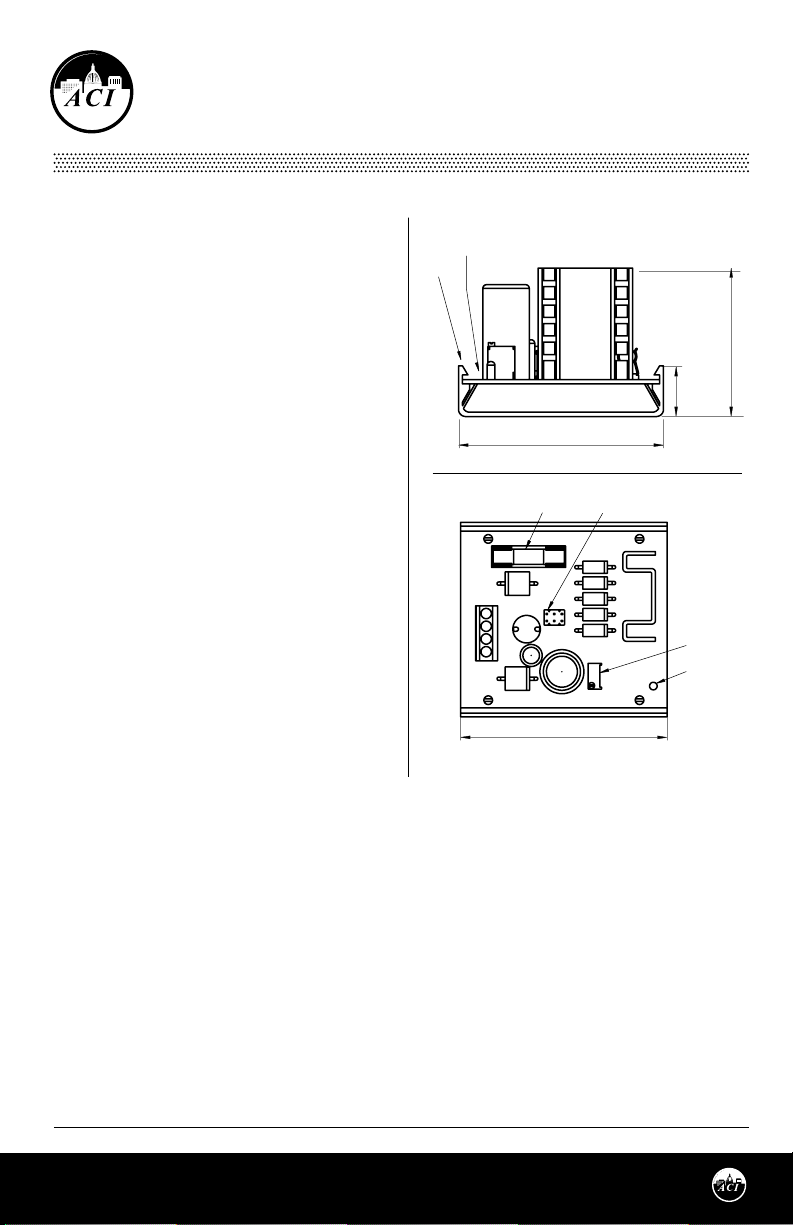
OUTPUT SELECTION JUMPERS
HALF WAVE - FULL WAVE RECTIFICATION
• The A/PS24 comes with the option of selecting
either a Full-Wave or Half-Wave output
depending on your application needs. All power
supplies are shipped from the factory in
Half-Wave mode.
• Make sure there is no power applied to the unit when changing jumpers. Failure to do so may
harm the unit or cause damage to any other device connected to the power supply.
HALF-WAVE VERSUS FULL-WAVE INDENTIFICATION
• If a device is half-wave, the signal common will typically be connected to the AC minus (-)
terminal on the device. Therefore, with no power applied, take an ohmic measure between
signal common and AC (-) using a DMM; the reading should measure less than two (2) ohms.
• If a device is full-wave, the signal common and the AC (-) will read overload or open when
measured with a DMM.
HALF-WAVE JUMPER SETTING
FULL-WAVE JUMPER SETTING
FULL
FULL
HALF
HALF
J1
J1

Automation Components, Inc.
2305 Pleasant View Road | Middleton, WI 53562
Phone: 1-888-967-5224 | Website: workaci.com
Page 3
Version 4.0
I0000824
VOLTAGE OUTPUT ADJUSTMENT
The output is factory set to 24 VDC, but can be adjusted from 1.5 to 26VDC. The voltage output
can be changed by adjusting the P1 turn pot with a flat-head screwdriver. Rotate the turn pot
screw clockwise to increase the voltage output, or rotate the turn pot screw counter-clockwise
to decrease the voltage output.
OUTPUT CURRENT
The maximum output current (mA) will be dependent on multiple factors, including ambient
room temperature, voltage, etc. The graph below shows the minimum (bottom line) and
maximum (top line) current output.
PRODUCT SPECIFICATIONS
WARRANTY
The ACI A/PS24 is covered by ACI’s Five (5) Year Limited Warranty, which is located in the front of
ACI’S SENSORS & TRANSMITTERS CATALOG or can be found on ACI’s website: www.workaci.com.
W.E.E.E. DIRECTIVE
At the end of their useful life the packaging and product should be disposed of via a suitable
recycling centre. Do not dispose of with household waste. Do not burn.
22 VAC to 26 VAC, 50/60Hz; or 30 VDC to 36 VDC
24 VDC
1.5 VDC to 26 VDC
Jumper Selectable
Built-in current limiting thermal protection
Fuse, 3.15A/250 VAC, 5x20 mm, fast acting (Littelfuse 02173.15MXP or equivalent)
32ºF to 158ºF (0ºC to 70ºC)
5% to 95% RH non-condensing
Screw Terminal Blocks | 14 AWG (2.1 mm
2
) to 22 AWG (0.33 mm
2
)
4 lb-in (0.5 Nm) maximum
Supply Power
Output Voltage – Factory Set
Output Adjustment Range
Half-Wave/Full-Wave Selection
Overload Protection
Ground-Loop Protection
Operating Temperature Range:
Operating Humidity Range:
Connections | Wire Size:
Terminal Block Torque Rating:
AMBIENT AIR TEMPERATURE | 77ºF (25ºC)
Volts (DC)
5 10 12 15 18 20 24 27
MAX
0.605
MIN
0.325

Automation Components, Inc.
2305 Pleasant View Road | Middleton, WI 53562
Phone: 1-888-967-5224 | Website: workaci.com
Page 4
Version 4.0
I0000824
Automation Components, Inc.
2305 Pleasant View Road
Middleton, WI 53562
Phone: 1-888-967-5224
Website: workaci.com
Table of contents