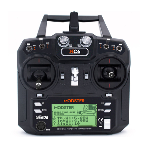
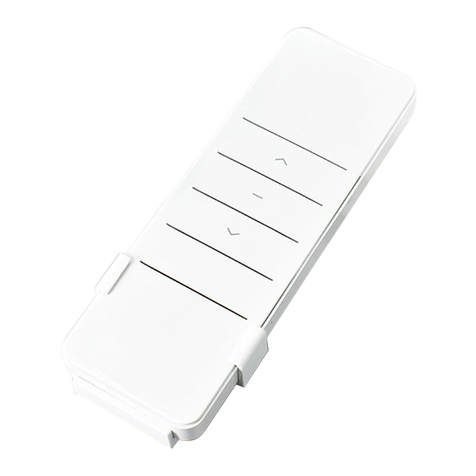
aci 2002 User manual

Remote Control Systems
Remote Control Systems PAGE: 1
200, 400, and 500 Series
Remotes-0214
2721 NE 4th Ave Pompano FL 33064 | (954) 367-6116 Visit WWW.ACIHOIST.COM for the most current information
200 Series
400 Series 500 Series
REMOTE CONTROL SYSTEMS
OPERATION MANUAL

Remote Control Systems PAGE: 2
200, 400, and 500 Series
Remotes-0214
2721 NE 4th Ave Pompano FL 33064 | (954) 367-6116 Visit WWW.ACIHOIST.COM for the most current information
TABLE OF CONTENTS
1.0 WARRANTY .............................................................................................................................................................. 4
2.0 SAFETY PRECAUTIONS........................................................................................................................................... 5
2.1 Safety Alert Symbols...................................................................................................................................... 5
2.2 Operating Precautions ................................................................................................................................... 6
2.2.1 Attention ......................................................................................................................................... 6
2.2.2 Precautions (500 Series)................................................................................................................. 6
2.2.3 Emergency Procedures (500 Series)............................................................................................... 6
3.0 GENERAL OPERATION (500 SERIES)..................................................................................................................... 7
3.1 Transmitter Configuration .............................................................................................................................. 7
3.1.1 Model 5008AB................................................................................................................................ 8
3.1.2 Model 50011AB.............................................................................................................................. 9
3.2 General Operation ........................................................................................................................................10
3.3 Special Functions Operation.........................................................................................................................10
3.3.1 Power-On
Operations
...................................................................................................................10
3.3.2 Acceleration Operation ..................................................................................................................11
3.3.3 Inching Operation..........................................................................................................................11
4.0 FUNCTION SETTINGS (DEFINED BY CUSTOMER) .............................................................................................. 12
4.1 Pushbutton Function Setting:........................................................................................................................12
5.0 CORRESPONDENCE BETWEEN PUSHBUTTON AND RELAY OUTPUT (500 SERIES) ....................................... 16
6.0 ID-CODE REMOTE SETTING (500 SERIES) .......................................................................................................... 18
7.0 RECEIVER VOLTAGE SELECTION (500 SERIES) ................................................................................................. 20
7.1 Switch the plug to choose voltage ................................................................................................................20
8.0 BOARD LAYOUTS .................................................................................................................................................. 21
8.1 Transmitter PC Board Layout (200 & 400 Series) ..........................................................................................21
8.2 Receiver PC Board Layouts (200 & 400 Series).............................................................................................22
8.3 Independent COM Line.................................................................................................................................25
9.0 FREQUENCY CHANGE (200, 400, & 500 SERIES) ................................................................................................ 26
9.1 Procedures...................................................................................................................................................26
9.2 VHF Band Conversion Table.........................................................................................................................28
9.3 UHF Band Conversion Table ........................................................................................................................29
9.4 Changing RO/START N.O. (normally open) INTO N.C. (normally closed)......................................................30
10.0 TROUBLESHOOTING........................................................................................................................................... 31
11.0 WIRING DIAGRAMS ............................................................................................................................................. 32
12.0 DIMENSIONS & SPECIFICATIONS...................................................................................................................... 34
12.1 Dimensions.................................................................................................................................................34
12.1.1 500 Series: Model 5008 ...............................................................................................................34
12.1.2 500 Series: Model 50011 .............................................................................................................35

Remote Control Systems PAGE: 3
200, 400, and 500 Series
Remotes-0214
2721 NE 4th Ave Pompano FL 33064 | (954) 367-6116 Visit WWW.ACIHOIST.COM for the most current information
12.1.3 200 Series Receiver.....................................................................................................................36
12.1.4 400 Series Receiver.....................................................................................................................37
12.2 Specifications .............................................................................................................................................38
12.2.1 200 Series ...................................................................................................................................38
12.2.2 400 Series ...................................................................................................................................39
12.2.3 500 Series ...................................................................................................................................40

Remote Control Systems PAGE: 4
200, 400, and 500 Series
Remotes-0214
2721 NE 4th Ave Pompano FL 33064 | (954) 367-6116 Visit WWW.ACIHOIST.COM for the most current information
1.0 WARRANTY
Every product is thoroughly inspected and tested before it is shipped from the factory. If any problem develops within
one year, return the product prepaid to the factory. If an inspection reveals that the problem is caused by defective
workmanship or material, repairs will be made without charge and the product will be returned with the shipping prepaid.
Excluded Items
This warranty does not cover:
Deterioration caused by normal wear, abuse, chemical or abrasive actions, improper
maintenance or excessive heat.
Problems resulting from repairs, modifications, or alterations made by people other
than factory or ACI representatives.
If the product has been abused or damaged due to an accident.
If repair parts or accessories other than ACI equipment are used on the product; they
are warranted only to the extent that they are warranted by the manufacturer of said
parts or accessories.
Remarks
EXCEPT AS STATED HERE, ACI MAKES NO OTHER WARRANTIES, EXPRESS OR IMPLIED, INCLUDING WARRANTIES
FOR A PARTICULAR PURPOSE.
Alterations or modifications of equipment and use of non-factory repair
parts can lead to dangerous operation and injury.
To avoid injury:
DO NOT alter or modify equipment.
DO NOT use equipment to lift, support or otherwise transport people.
DO NOT suspend unattended loads over people.

Remote Control Systems PAGE: 5
200, 400, and 500 Series
Remotes-0214
2721 NE 4th Ave Pompano FL 33064 | (954) 367-6116 Visit WWW.ACIHOIST.COM for the most current information
2.0 SAFETY PRECAUTIONS
2.1 Safety Alert Symbols
Throughout this manual are steps and procedures that can prevent hazardous situations, the following symbols are used
to identify the degree or level of hazard seriousness.
DANGER, WARNING AND CAUTION NOTICE
Symbol
Description
Danger
Indicates an imminently hazardous situation which, if not
avoided, will result in death or serious injury and
property damage.
Warning
Indicates an imminently hazardous situation which, if not
avoided, could result in death or serious injury and
property damage.
Caution
Indicates a potentially hazardous situation which, if not
avoided, may result in minor or moderate injury or
property damage.
Notice
Notifies people of installation, operation or maintenance
information which is important but not directly hazard
related.
Failure to read and comply with any of the limitations noted in this manual can result in serious bodily
injury or death, and/or property damage.

Remote Control Systems PAGE: 6
200, 400, and 500 Series
Remotes-0214
2721 NE 4th Ave Pompano FL 33064 | (954) 367-6116 Visit WWW.ACIHOIST.COM for the most current information
2.2 Operating Precautions
2.2.1 Attention
1. Due to the complex nature of equipment, it is necessary to read the entire manual before installation.
2. Never allow any unauthorized personnel to dismantle equipment as this may cause equipment damage.
3. The equipment has been stringently tested for quality assurance before delivery from factory. However, it must
not be used in extremely dangerous situations or where damage may result.
4. After operation, switch off crane main power as well as receiver unit and remove rotary key from transmitter unit.
5. Keep the transmitter in a safe place when not in use to avoid any unintentional operation.
6. The crane should be equipped with a main power relay, limit switch, and other safety devices required.
7. Do not use this device during an electrical storm or where there are conditions of high electrical interference.
8. Always check transmitter batteries and receiver input power condition before operation.
9. The installation and maintenance service is allowed only when the crane and receiver power are off to avoid
electrical shock.
10. The contents of the manual may be ammended by the manufacturer without notice.
11. The specification and function is subject to change without notice by manufacturer.
2.2.2 Precautions (500 Series)
1. Press EMS button and switch off main power of crane and receiver after operation. Then, remove transmitter
rotary key and keep in a safe place.
2. The following may cause receiver response delay and you should stop operation immediately when these
situations occur.
a. Beyond operating range.
b. During severe radio interference.
3. Remove transmitter batteries when not in use for a long period of time.
4. To extend product life, please follow the standard operating procedure and maintain system regularly.
2.2.3 Emergency Procedures (500 Series)
In case of emergency, please follow the procedure below:
5. Press EMS button and stop operation.
6. Switch rotary key to “OFF” position and remove it from transmitter unit.
7. Switch off crane main power.
8. Contact the authorized distributor for further assistance.

Remote Control Systems PAGE: 7
200, 400, and 500 Series
Remotes-0214
2721 NE 4th Ave Pompano FL 33064 | (954) 367-6116 Visit WWW.ACIHOIST.COM for the most current information
3.0 GENERAL OPERATION (500 SERIES)
3.1 Transmitter Configuration
1. Antenna
2. Emergency Stop
3. LED indicator
4. Motor Pushbutton
5. Auxiliary Pushbutton R1-R4
6. F1 Pushbutton
7. Start Pushbutton
8. Battery Cover
9. Rotary Key Switch
10. Security Key

Remote Control Systems PAGE: 8
200, 400, and 500 Series
Remotes-0214
2721 NE 4th Ave Pompano FL 33064 | (954) 367-6116 Visit WWW.ACIHOIST.COM for the most current information
3.1.1 Model 5008AB

Remote Control Systems PAGE: 9
200, 400, and 500 Series
Remotes-0214
2721 NE 4th Ave Pompano FL 33064 | (954) 367-6116 Visit WWW.ACIHOIST.COM for the most current information
3.1.2 Model 50011AB

Remote Control Systems PAGE: 10
200, 400, and 500 Series
Remotes-0214
2721 NE 4th Ave Pompano FL 33064 | (954) 367-6116 Visit WWW.ACIHOIST.COM for the most current information
3.2 General Operation
1. Install two (2) new AA-size alkaline batteries in the battery box of MODEL 50011, then insert into battery case
of transmitter; or battery chamber of 5008, and screw in transmitter's bottom cover. Make sure the "+" and "-
"directions are correct.
2. Insert security key in the
"OFF" position.
3. Turn on the power
according
to the "Power-On
Modes
".
Note: LED indicator will flash red if proper
procedures
are not
followed.
4. Operate transmitter by pressing each
pushbutton.
5. After operation, perform the following
procedures
in
sequence:
(1) Press EMS
mushroom,
(2) Rotate security key or rotary key switch
counterclockwise
to the
"
OFF
"
position,
(3) remove key and keep it in a safe place, (4) remove batteries if not to
be
used for a long period of
time.
3.3 Special Functions Operation
3.3.1 Power-On
Operations
Power-On means that the Main-Relay on the receiver will switch on as soon as
the
transmitter sends a signal
and then the receiver will be on standby for
continuous
control. There are 2 options for "Power-On
Mode":
1. Any
Pushbutton
Power-On
Mode
a. Rotate
"EMS" mushroom clockwise
45°and pull
out.
b. Turn security key clockwise to "ON" position for 50011; Rotary key
switch
clockwise to
"ON"
for
5008.
c. Press any
pushbutton
on the transmitter. This will turn on the power as well as execute the
function of
pushbutton.
2.
"
START'
'
Pushbutton Power-On Mode
a. Rotate "EMS" mushroom clockwise 45° and pull out.
b. Turn security key clockwise to "ON" position for 50011; Rotary key switch clockwise to "ON" for
5008.
c. Press
"START"
pushbutton on the transmitter to turn on power for 50011; Continue to turn rotary key
switch to
"START"
position to turn on power for 5008 (the rotary key switch will return to "ON"
position automatically after being released
.

Remote Control Systems PAGE: 11
200, 400, and 500 Series
Remotes-0214
2721 NE 4th Ave Pompano FL 33064 | (954) 367-6116 Visit WWW.ACIHOIST.COM for the most current information
3.3.2 Acceleration Operation
1. For 50011
:
The
"START"
pushbutton is acceleration pushbutton.
2. For 5008: The
"START"
key is the acceleration key.
3. When a motion is in the second speed, quick touch of acceleration pushbutton will accelerate the speed.
Repeated touch of acceleration pushbutton will increase the speed. Note: When accelerating, the motion
pushbutton must be depressed and held in the second speed. If motion pushbutton is released
,
there will
be
no
acceleration and speed will return to zero.
3.3.3 Inching Operation
1. "Start" pushbutton is set for "inching" function.
2. Press and hold inching pushbutton
.
3. Press any motion pushbutton to perform the inching motion. Note: The other pushbutton of transmitter
must be released before pressing the inching
pus
hbutton.

Remote Control Systems PAGE: 12
200, 400, and 500 Series
Remotes-0214
2721 NE 4th Ave Pompano FL 33064 | (954) 367-6116 Visit WWW.ACIHOIST.COM for the most current information
4.0 FUNCTION SETTINGS (DEFINED BY CUSTOMER)
4.1 Pushbutton Function Setting:
UP/DOWN, NORTH/SOUTH, EAST/WEST,R1/R2, R3/R4 Pushbutton Function Setting
Item
Title
Content
Description
1
Button
Function
1.
Normal/Normal
2. Toggle/Toggle
3. No/Off
4.
Normal/Toggle
5. Dual
Motor(1)/Dual
Motor
(1)
6. Dual
Motor(2)/Dual
Motor
(2)
7. 3 Speed Accel. / 3 Speed
Accel.
8. Digital
Accel. / Digital Accel.
9.
Normal/Dual
Motor(1)
10.
Normal/Dual
Motor(2
)
11. Toggle/Dual Motor
(1)
12. Toggle/Dual Motor
(2)
13. Toggle/3 Speed
Accel.
14.
Synthesis/Synthesis
NOTE: 500 Series Model
5008
Up/Down Pushbuttons
are for
full
functions,
the rest are for
Normal,
Toggle, On, Off only.
Normal: The relative relay is "ON" when
the
Pushbutton
is pressed and
held.
The relative relay is "OFF" when the
Pushbutton
is
released.
Toggle:
Press the
Pushbutton
and release
once
for
"ON", re-press and release for
"OFF"
ON & OFF: Two relative
Pushbuttons
are set
to
respectively control the same relay. If a Push- button
set as "ON" is pressed and released,
the
relay remains
conductive.
At this time, the other
Pushbutton
can't change the situation of
this
relay
except the
Pushbutton
set as
"OFF".
Dual Motor(1): When
Pushbutton
is
released
from
2nd speed and back to 1st, the 1st
speed
relay is
activated again til the
Pushbutton is
totally
released.
Dual
Motor(2):
When
Pushbutton
is
released
from 2nd speed and back to 1st, the 1st
speed
relay
is not activated but
bypassed.
3 Speed Accel.: Use "START" to accelerate
to
3
Speed
Digital Accel.: Use "START" to accelerate to
4
Speed
Synthesis:
Three relays used for two
dual-
speed
motions, the fourth relay works as
independent
"TOGGLE" ON and OFF
function
when two
Pushbuttons
pressed
simultaneously
and
again.
2
Acceleration
Delay
0-4.0 seconds
This function is used to set the time
interval
between
acceleration
relays (i.e.
conduction
delayed time of
acceleration
delay. It is
suitable
for accelerative
operation
to prevent the
crane
from running at a higher
speed to damage
the motor.
3
EMS
Control
1. Control by EMS
2. Bypass EMS
Control by EMS means the
corresponding
relay of
function
Pushbutton
is
controlled by
EMS
mushroom
or
emergency
stop
signal.
Bypass EMS
means the
corresponding relay
of function
Pushbutton
will not be
controlledby
EMS
mushroom
or
emergency
stop
signal.
4
Interlock
Function
1. Interlock Delay
0-2 seconds
2.
Non-Interlocked
Interlock: If it is
dangerous
or
improper to
operation
two motions at the same
time,
select
"INTERLOCK". Delay time means
the
time interval
before next motion is
valid.
Non-Interlocked: If two motions are safe or
irrelevant to operate at the same time,
select
"NON-INTERLOCKED".

Remote Control Systems PAGE: 13
200, 400, and 500 Series
Remotes-0214
2721 NE 4th Ave Pompano FL 33064 | (954) 367-6116 Visit WWW.ACIHOIST.COM for the most current information
Start/F1 Pushbutton Function Setting
Item
Title
Content
Description
1
Button
Function
START
F1
Inching:
"Inching"
means that once the Push-
button is pressed, relative relay will be
activated
within a certain period of time to operate a
short
but precise
movement.
Press and hold
inching
Pushbutton
and then press motion
Pushbutton
to
perform the
inching motion.
Acceleration: When the motion is at
the
2nd speed, quick
pushing
on
acceleration
Pushbutton
will
accumulate
one speed
each
time and the relative relay will turn on
accord-
ingly. When
accelerating,
the motion
Pushbutton
must be pressed and held in the 2nd speed. If
motion
Pushbutton
is released, there will be
no
acceleration
and the speed will return to
zero.
1.
Normal
2. Toggle
3.
Inching/
Accel.
1.
Normal
2. Toggle
3. Dual Motor
(1)
4. Dual Motor
(2)
2
EMS
Control
1. Control by EMS
2. Bypass EMS
Control by EMS means the
corresponding relay
of function
Pushbutton
is
controlled
by EMS
mushroom
or
emergency
stop
signal.
Bypass EMS means the
corresponding
relay of
function
Pushbutton
will not be
controlled
by EMS
mushroom
or
emergency
stop
signal.
3
Inching
0.1
-4.0 seconds
Select the time interval of each
inching motion.
4
Acceleration
Delay
0-4.0 seconds
Select the time interval for each
acceleration.

Remote Control Systems PAGE: 14
200, 400, and 500 Series
Remotes-0214
2721 NE 4th Ave Pompano FL 33064 | (954) 367-6116 Visit WWW.ACIHOIST.COM for the most current information
Transmitter Function Setting
Item
Title
Content
Description
1
POWER-ON
Mode
1. Any
Pushbutton
2. START
Pushbutton
Any
Pushbutton:
When
mushroom
is
released
and security or rotary key is at "ON"
position, the
receiver will be "POWER-ON"by
pressing any
Pushbutton
on transmitter.
START
Pushbutton:
When
mushroom
is
released
and security or rotary key is at "ON"
position, the
receive will be "POWER-ON" only by
pressing
"START"
Pushbutton
on transmitter.
2
Transmit
Mode
1.
Non-Continuous
2.
Continuous
15
seconds-
30 seconds OFF
3.
Continuous
Never OFF
Non-Continuous: Once the receiver is "POWER-
ON", the transmitter will transmit signal only
when
Pushbutton
is pressed. This mode can save
the
power of transmitter.
Continuous Due Time OFF: Transmitter will
transmit signal
continuously
during "POWER-
ON" and stop
sending
signal if no Pushbutton is
pressed within selected
timeframe.
Continuous Never OFF:Transmitter will
keep
sending
signal unless turned off manually.
3
Auto Off
1.
Enable
2.
Disable
Enable: When Transmit Mode is set
for
continuous,
it will send an EMS signal to "POWER-
OFF" the receiver if it is set to auto off in a
certain
timeframe.
Disable: Disable the function to send EMS
signal
to receiver before the transmitter is off.
4
Normal OP LED
1.
ON
2. ON Every 1
-4
seconds
3. OFF
ON: LED indicator will glow with green color
when
transmitter is
transmitting.
It still works for
warning
and fault
indication
with first
priority.
ON Every
1
- 4
seconds: LED indicator is
flashing
with green color every 1
-4
seconds.
OFF: LED indicator will not work during
normal
operation
in order to save power. But, it is still
available for warning and fault
indication.
5
Powersaving
1.
Enable
2.
Disable
Enable: By using firmware to control
frequency
transmission
cycle period, thus to reduce
power
consumption
of transmitter.
Simultaneously, the
operating
distance will be
decreased
when
the
"POWERSAVING" mode is
enabled.
Disable: Disable this
function.
6
Remote
Setting
1.
Enable
2.
Disable
Enable: Allow the transmitter to do
ID-Code
remote
setting.
Disable: Not allow ID-Code remote setting
on
transmitter.

Remote Control Systems PAGE: 15
200, 400, and 500 Series
Remotes-0214
2721 NE 4th Ave Pompano FL 33064 | (954) 367-6116 Visit WWW.ACIHOIST.COM for the most current information
Receiver Function Setting
Item
Title
Content
Description
1
Passive
Act
1. Relay OFF
2. POWER OFF
Passive Act:The function of this item is used
to
set the reaction of receiver when no
command
signal is received from transmitter in certain
time
(the default time is 0.5
seconds).
Relay OFF means the Main Relay is still "ON"
but
the other relays with the "NORMAL:'function are all
de-energized.
It is not necessary to
re-commence
the
procedure
of "POWER-ON" again to
continue
operating.
POWER OFF means the Main Relay and all of
the other relays with the "NORMAL:' and
"Control
by EMS" functions are going to
de-energize
and
it is essential to
re-commence
the procedures of
"POWER ON" again to continue
operation.
2
Passive Act Tim-
ing
0.1
-4
seconds
The duration
working
time of receiver
between
passive act is activated and the power or relay is
really OFF.
3
Auto-OFF (RX)
1.
None-Execute
2. 10
minutes~4 hours
POWER OFF
Enable: When Transmit Mode is set for
continu-
ous, it will send an EMS signal to "POWER-OFF"
the receiver if it is set to auto off in a certain
time-
frame.
Disable: Disable the function to send EMS
signal
to receiver before the transmitter is off.
4
Remote
Setting
1.
Enable
2.
Disable
Enable:AIIow
the receiver to do ID-Code
remote
setting.
Disable: Not allow ID-Code remote setting
on
receiver.

Remote Control Systems PAGE: 16
200, 400, and 500 Series
Remotes-0214
2721 NE 4th Ave Pompano FL 33064 | (954) 367-6116 Visit WWW.ACIHOIST.COM for the most current information
5.0 CORRESPONDENCE BETWEEN PUSHBUTTON AND RELAY
OUTPUT (500 SERIES)
Note: When pushbutton is released from 2nd speed and back to 1st one, the 1st speed relay is activated again until
the pushbutton is completely released.

Remote Control Systems PAGE: 17
200, 400, and 500 Series
Remotes-0214
2721 NE 4th Ave Pompano FL 33064 | (954) 367-6116 Visit WWW.ACIHOIST.COM for the most current information
Note: When Up and Down pushbuttons are pressed at the same time, the second relay works as “Toggle”, released
when they are pressed simultaneously again.

Remote Control Systems PAGE: 18
200, 400, and 500 Series
Remotes-0214
2721 NE 4th Ave Pompano FL 33064 | (954) 367-6116 Visit WWW.ACIHOIST.COM for the most current information
6.0 ID-CODE REMOTE SETTING (500 SERIES)
The use of Copier (500 Series)
1. Insert the six (6) pins of the female plug into the male socket inside the TX or RX of the 500 Series.
2. To copy and save the data from TX or RX, put the magnetic key onto
the
receptor to connect. To transfer
the saved data from the copier to TX or RX, release the magnetic key from the receptor.
3. Press and release the "1"
pushbutton
(or 2 or 3) to copy and save the
data
(when the magnetic key is
on) from TX or RX, after the green indicator light has flashed, the transfer is finished,
disconnect
the
plug. Complete the same
procedure
to transfer the data from copier to TX or RX (when magnetic key is
off). Note:
(1) Make sure the power of TX or RX is off when
copying.
(2) The copier can copy both function settings and ID-Code, but to pair
the
crystal is still essential to
match both TX and RX for
communicating
with each other.
ID-Code Remote Setting (500 Series)
ID-Code remote setting allows you to pair the new TX or RX if one of them is
damaged.
Using ID-Code remote
setting will allow both the TX and RX to have
the
same ID-Code.
Please make sure the following conditions are met before ID-Code remote setting:
1. Both TX and RX are of the SAME model and frequency.
2. Place the transmitter as close as possible to the receiver to avoid interference.
3. Turn off the RX power for at least 10 seconds and turn it on again.
ID-Code Remote Setting Instructions
1. Press and hold the transmitter EMS button and "UP"
pushbutton.
2. Press "DOWN"
pushbutton
four (4) times and then release "EMS
&
UP"
push
buttons when the red light
on the transmitter is flashing.
3.
Start the system as you usually
would.

Remote Control Systems PAGE: 19
200, 400, and 500 Series
Remotes-0214
2721 NE 4th Ave Pompano FL 33064 | (954) 367-6116 Visit WWW.ACIHOIST.COM for the most current information
ID-Code Remote Setting (continued)
ATTENTION:
In case ID-Code remote setting fails, repeat the instructions above within 4
minutes.
ID-Code remote setting is available for ID Code only. It will not change
function settings.
Within the operating distance, all same model systems on the same frequency
will be paired with the transmitter's ID Code.
A jumper added inside the receiver is necessary to enable the ID-Code remote
setting function.
Model 5008
Model 50011
Jumper to add for ID-
Code remote setting

Remote Control Systems PAGE: 20
200, 400, and 500 Series
Remotes-0214
2721 NE 4th Ave Pompano FL 33064 | (954) 367-6116 Visit WWW.ACIHOIST.COM for the most current information
7.0 RECEIVER VOLTAGE SELECTION (500 SERIES)
Receiver Voltage Selection
There are two (2) types of power voltages (DC
&
AC) available for the 500 Series:
1. DC
Type:
Input Voltage: 12 ~ 24 VDC Relay Contact:
1OA-36
VDC
2. AC
Type:
Three (3) different AC
transformers:
48/110/220V, 48
/
220/380V,
3. 110/220/380V. Disconnect the AX's power, select the proper voltage and plug in
the connector.
7.1 Switch the plug to choose voltage
Transmitter Battery Information
Two (2) AA size alkaline batteries are required for the transmitter. The LED will
flash
green when the battery
power is sufficient. The LED will flash red when the battery power is
low.
Note: The operating distance will become shorter and intermittent when the
battery
is low (replace with new
batteries when battery power is
low).
DO NOT USE RECHARGABLE BATTERIES.
This manual suits for next models
6
Table of contents
Other aci Remote Control manuals


