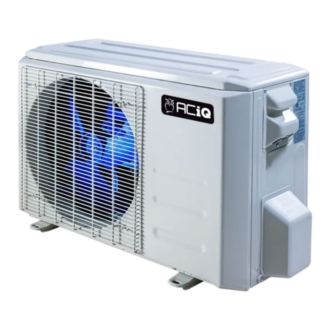
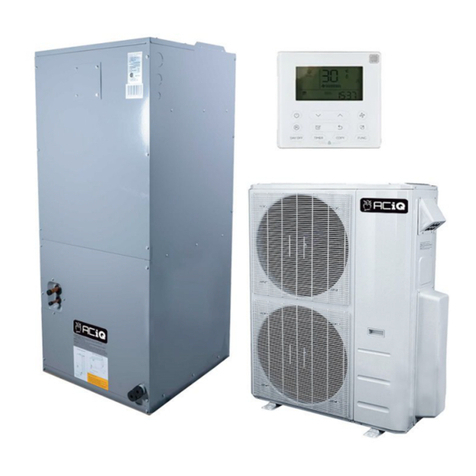
ACIQ ACIQ-12W-EZ115 Repair manual

Owner’s Manual &
Installation Manual
ACIQ EZ CONNECT HEAT PUMP SYSTEM
COVERS MODELS
ACIQ-12W-EZ115/ACIQ-12Z-EZ115
ACIQ-18W-EZ230/ACIQ-18Z-EZ230
ACIQ-24W-EZ230/ACIQ-24Z-EZ230
ACIQ-36W-EZ230/ACIQ-36Z-EZ230
IMPORTANT NOTICE:
Read this manual carefully before
installing or operating your new heat
pump unit. Make sure to save this
manual for future reference.

Instruction Manual
ACIQ EZ - CONNECT
HEAT PUMP SYSTEM
ACIQ
2331 West State Route 55 Troy, Ohio 45373
Phone (937) 335-2626 Fax (937) 339-2776
IMPORTANT NOTE:
Read this manual carefully before
installing or operating your new heat
pump unit. Make sure to save this
manual for future reference. Please
check the applicable models, technical
data and manufacturer information
from the Owner’s Manual.

TABLE OF CONTENTS
Title Page ............................................................................02
Safety Precautions.............................................................03
Owners’ Manual
Tools Required...................................................................07
Getting Started...................................................................08
Parts Included....................................................................09
Installation Manual
Installation..........................................................................11
Electrical Connections.......................................................16
Diagram..............................................................................17


BASIC TOOLS LIST
1. 25 FT TAPE MEASURE
2. 2 FT LEVEL
3. UTILITY KNIFE
4. #2 PHILIPS SCREWDRIVER
5. 5MM ALLEN KEY
6. NEEDLE NOSE PLIERS
7. STANDARD SET OF DRILL BITS
8. CORDED OR CORDLESS DRILL
9. 3.5” HOLE SAW WITH ARBOR BIT
10. (2) 8” ADJUSTABLE WRENCHES
11. SPRAY BOTTLE FOR SOAPY WATER SOLUTION

THINGS TO CHECK BEFORE GETTING STARTED
The circuit breaker is the appropriate size and type for the equipment
being installed. Refer to the label on the outdoor unit for specications.
The circuit breaker is in the o position before attempting to install the
system. Power to the equipment should never be live while attempting to
install or adjusting the system.
The Gray and Blue refrigerant caps are intact on the
indoor unit, outdoor unit and line set connections.
If caps are missing, please stop and contact us
immediately.
UNBOXING THE EQUIPMENT
INDOOR SECTION
When unboxing the indoor section, make sure to check for any physical
damage to the air handler. Also make sure the connection cable is intact
and physically connected to the air handler.
If the air handler section is damaged or the connection cable is
disconnected/missing, please stop immediately and give us a call.
IMPORTANT
BEFORE THROWING AWAY THE BOX, BE SURE TO REMOVE THE
CARDBOARD TEMPLATE FOR SECURING THE AIR HANDLER TO THE
WALL. WITHOUT THE TEMPLATE INSTALLATION WILL BE MORE
DIFFICULT.
1.
2.
3.

INCLUDED IN INDOOR SECTION BOX WILL BE A CONTENTS BAG Of2 MIXED PARTS
THE PARTS BAG SHOULD INCLUDE THE FOLLOWING
NetHome Plus Wi-Fi Adapter - Used for connecting the ACiQ EZ-Connect Heat Pump
system to your Wi-Fi network.
Hand held Remote Control - Used for temperature control of the ACiQ EZ-Connect
Heat Pump system.
Remote Wall Bracket - Used for mounting the Hand held Remote Control in a
convenient location.
Mounting Hardware - Screws and Wall Anchors (xS) Used for securing the mounting
plate of the indoor unit to the interior wall.
batteries (x2) - Used for powering Hand held Remote Controller
Drain Joint - Used to drain excess condensation water away from the outdoor
condenser.
Foam insulation (x2) - Used for wrapping joints where the EZ-Connect lineset will
meet the indoor air handler factory piping connections.
Tar Tape (x2)- Used for wrapping joints where the EZ-Connect lineset will meet the
indoor air handler factory piping connections. Helps with vibration noise reduction.
Remote Control & Owners Manuals - Used for system control and future reference
material.
1.
2.
3.
4.
5.
6.
7.
8.
9.

WHEN UNBOXING THE OUTDOOR SECTION, MAKE SURE
THE TO CHECK FOR ANY PHYSICAL DAMAGE TO THE
CONOENSER.
IF THE CONDENSER SECTION IS DAMAGED, PLEASE STOP
IMMEDIATELY AND GIVE US A CALL.
OUTDOOR SECTION
IMPORTANT
25ft Refrigerant Lineset - Used for connecting the indoor air handler to the
outdoor condenser.
Vibration Pads (x4)- Used for reducing vibration noise between outdoor
condenser and the mounting surface.
Drain Tubing- Used for connecting to the factory drain tubing to remove
condensation from the indoor air handler
Wall Sleeve- Used for protecting the refrigerant lines, communication cable, and
drain tubing as it is passed through the wall.
Beauty Cap- Used for capping of the hole drilled for the refrigerant lines,
communication cable, and drain tubing on the outside portion of the home.
UV Tape (x3)- Used for bundling the lineset, communication cable, and drain
tubing before it is passed through the outside wall.
INCLUDED IN OUTDOOR SECTION BOX WILL BE A CONTENTS
BAG OF MIXED PARTS. THE PARTS BAG SHOULD INCLUDE THE
FOLLOWING
1.
2.
3.
4.
5.
6.

Choose a location where the indoor unit will be installed. Pick a location that has
at least 6'' of clearance from the top of the ceiling and 5'' from each side of the air
handler. Make sure the installation location in not in direct sunlight, away from
any obstacles that may block air circulation, and at least 3ft away from any other
electronic devices.
Locate the carboard wall template included with the indoor air handler. Using a
level, make sure the template is straight and level before attaching to the wall.
Using painters tape, attach the template to the wall the air handler will be installed
on.
Using the template, mark and drill the holes for the mounting plate to attach to
the wall. Also mark and drill the center point for the 3.5 hole to the outside. When
drilling through the wall, drill at a slight downward angle to help pass through the
lineset, communication wire, and drain tubing bundle.
Remove the wall template.
Locate the metal wall bracket attached to the backside of the indoor air handler.
From the factory, it is attached to the air handler with a sheet metal screw. The
screw is located near the center of the air handler. Remove the screw and wall
bracket from the air handler.
Using the included mounting hardware, install the wall anchors and screw the wall
bracket into the predrilled holes in Step 4.
Pass the wall sleeve through the wall from inside to outside. From the outside, mark
the wall sleeve where it meets the outside wall. Remove the wall sleeve from the
inside and cut the sleeve down to size at the location just marked. This will make a
ush t for the wall sleeve and allow for the outdoor beauty cap to be installed on
the outside wall.
Reinstall the wall sleeve from the inside of the wall opening.
On the indoor air handler, locate the refrigerant line and drain tubing connections
on the back side of the unit. Carefully bend the connections outward to prepare
them to pass through the wall.
INSTALLATION
1.
2.
3.
4.
5.
6.
7.
8.
9.
10.

Bundle together the communication cable, refrigerant lineset connections,
and drain tubing connection for preparing to pass it through the wall. Wrap
the bundle together using the UV tape provided with the air handler. This will
protect the bundle and make sure it passes easily
through the wall sleeve.
IMPORTANT - Use two hands when bending out
the refrigerant lines, one hand near the base of the
connections to brace the factory connections and one
hand to bend the lineset. This will prevent the copper
from kinking as it is being bent.
IMPORTANT - Make sure the drain tubing is located
at the bottom of the bundle. This will allow for better
drainage and ensure no water backs up into the
indoor air handler.
Prepare to mount the indoor unit to the wall bracket. Carefully pass the bundle
through the wall making sure the drain tubing stays to the bottom of the
bundle. Place the top section of the air handler on to the bracket rst, making
sure to catch the clips on the wall bracket to the air handler itself. Once the top
clips are in place, press down on the air handler to lock the bottom to the wall
bracket.
IMPORTANT- This may be dicult for a single person
to manage. If you have a helper available, it would be
best to have them help balance out the unit as the
line bundle is being passed through the wall.
From the outside, pass the beauty cover for the wall through the lineset bundle
and push into place.
Carefully bend the bundle down the outside wall. Use two hands when
bending the copper connections like in step 10.
IMPORTANT- One hand to brace the copper as close to the outside wall as
possible and one hand to bend the copper itself. This will prevent the copper
from kinking as it is being bent down the wall.
Attach the drain tubing extension, provided with the
outdoor unit supply bag, to the factory drain tubing
connection. Route the drain tubing down the wall to a
location where the excess drainage water will not be an
issue.
11.
12.
13.
14.
15.

LINESET CONNECTIONS
Locate the refrigerant lineset provided with the outdoor unit. On a at, level
surface, carefully unroll the lineset to prepare and install at the factory connections
for the indoor unit just passed through the wall.
On the factory piping connections that were passed through the wall, remove the
gray and blue caps so you can prepare to install the lineset. On one end of the
lineset, also remove the gray and blue caps. Leave the other ends capped that will
be connected to the outdoor condenser.
Line up the factory connections to the lineset ttings. Hand tighten the rst few
threads and use the adjustable wrenches to tighten down the rest. Tighten unit all
the threads can't be seen, and the ttings are bottomed out together.
IMPORTANT - Be sure to use two wrenches when
tightening the ttings, one to back up the factory
connection, and one to screw the lineset side
together. this will prevent the copper from twisting
and breaking during installation.
Set the outdoor condenser in place. pick a location that has no airow obstructions
for the outdoor unit. make sure no combustible materials will be within proximity of
the unit.
IMPORTANT -makes sure if the unit is being mounted to a wall
bracket, it has 6'' of clearance from the back of the unit to the wall,
12'' around each side, and 80'' from the front discharge fan to ensure
proper operation.
If mounting the outdoor to a unit to a ground pad, make sure the
surface is at and level. on ground level installs, make sure the
unit has 12'' of clearance from the back of the unit to the wall, 12''
around each side, and 80'' from the front discharge fan to ensure
proper operation.
Remove the gray and blue caps on the other end of the refrigerant lineset not
installed yet. also remove the gray and blue caps at the connection ports for the
outdoor condenser.
16.
17.
18.
19.
20.

Repeat step 18 at the outdoor condenser. line up the condenser connections
to the lineset ttings. hand tighten the rst few threads and use the adjustable
wrenches to tighten down the rest. tighten unit all the threads can't be seen,
and the ttings are bottomed out together.
Locate the brass hexagonal valve caps just above the lineset connections. using
an adjustable wrench, remove the valve caps.
Insert a 5 mm allen key into the valve body assemblies. turn the valve body
counterclockwise to open the refrigerant valves. this will release the refrigerant
into the system.
IMPORTANT- be sure to use two wrenches when
tightening the ttings, one to back up the condenser
connection, and one to screw the lineset side together.
this will prevent the copper from twisting and breaking
during installation.
IMPORTANT - You will need to use a little bit of force to open the valve bodies
and start the threads. once the valve starts sp'inning, it will spin freely. keep
turning the valves counterclockwise unit you hit a good amount of resistance.
do not force further. now the valve body is completely open. do not close the
valve body after the refrigerant is released. it needs to stay open for proper
unit operation.
Re-install the brass hexagonal valve caps.
21.
22.
23.
24.

LEAK CHECKING SYSTEM AND FINAL LINE SET PREPARATIONS
Using a spray bottle, prepare a solution of soapy water to leak check the
ttings. The more suds in the solution, the easier any leaks will be to nd. Dish
soap and water works well for this process.
Spray down all the refrigerant lineset connections and ttings with the soapy
solution. Let the excess solution drip o the ttings and wait to see if bubbles
start forming at any of the connection points. If you see bubbles, wipe the
ttings down with a clean rag or paper towel and repeat the process. If bubbles
form again, a leak is present.
IMPORTANT - If a leak is found and present, the ttings
will need to be re-tightened down. After re-tightening the
ttings, repeat the leak check process again until no bubbles
are present.
Wipe down all the soapy water solution o the ttings using a clean rag or
paper towel.
Using the tar tape provided with the indoor air handler, wrap the factory
ttings and lineset connections. Press the tar tape into place around the ttings
and mold to the shape of the lineset. Cover the tar tape and ttings with the
insulation material provided with the air handler.
Using the UV tape provided with the outdoor condenser, wrap the lineset
bundle for where it exists the home down to the outdoor condenser.
25.
26.
27.
28.
29.

ELECTRICAL CONNECTIONS
IMPORTANT - PLEASE DOUBLE CHECK AND MAKE SURE YOU HAVE THE
CORRECT POWER SOURCE BEING USED FOR THE SYSTEM PURCHASED.
FOR THE 12K BTU SYSTEM, IT WILL REQUIRE A SINGLE POLE 15-AMP BREAKER,
115 VOLTS
FOR THE 18K BTU SYSTEM, IT WILL REQUIRE A DOUBLE POLE 20-AMP BREAKER,
240 VOLTS
FOR THE 24K BTlcJ SYSTEM, IT WILL REQUIRE A DOUBLE POLE 30-AMP
BREAKER, 240 VOLTS
FOR THE 36K BTU SYSTEM, IT WILL REQUIRE A DOUBLE POLE 40-AMP BREAKER,
240 VOLTS
THE ELECTRICAL WIRING COVER ON THE OUTDOOR CONDENSER AND PLACE
OFF TO THE SllDE.
REMOVE THE TWO ROUND BLACK KNOCKOUTS FROM THE WIRING COVER
PLATE.
INSTALL THE WIRE WHIP FROM THE DISCONNECT BOX USING THE RIGHT
HAND KNOCKOUT.
*FOLLOW THE DIRECTIONS IN THE WIRING DIAGRAM PROVIDED ON THE
NEXT PAGE FOR YOUR SPECIFIED UNIT
INSTALL THE COMMUNICATIONS CABLE FROM THE INDOOR AIR HANDLER
USING LEFT-HAND KNOCKOUT.
The design and specications are subject to change
without prior notice for product improvement. Consult
with the sales agency or manufacturer for details.
30.
31.
32.
33.

DIAGRAM FOR PREVIOUS PAGE
This manual suits for next models
7
Table of contents
Other ACIQ Heat Pump manuals
Popular Heat Pump manuals by other brands

Daikin
Daikin Altherma 3 R F installation manual

Aqua Comfort
Aqua Comfort XL Series Calibrations and Settings

Chiltrix
Chiltrix CX50 Installation and operation manual

Johnson Controls
Johnson Controls HMH7 Series installation manual

Riello
Riello NXHM Installation & owner's manual

Carrier
Carrier 38MURA installation instructions

Daikin
Daikin DRG0361DL00001S Service instructions

Daikin
Daikin RKS71FV1B Service manual

aquatherm
aquatherm AT75 Installation & operation manual

Viessmann
Viessmann VITOCAL 300-G Installation and service instructions

Daikin
Daikin EGSQH10S18AA9W Operation manual

Aquacal
Aquacal AUTOPILOT SIDEWINDER LTP0093 quick start guide