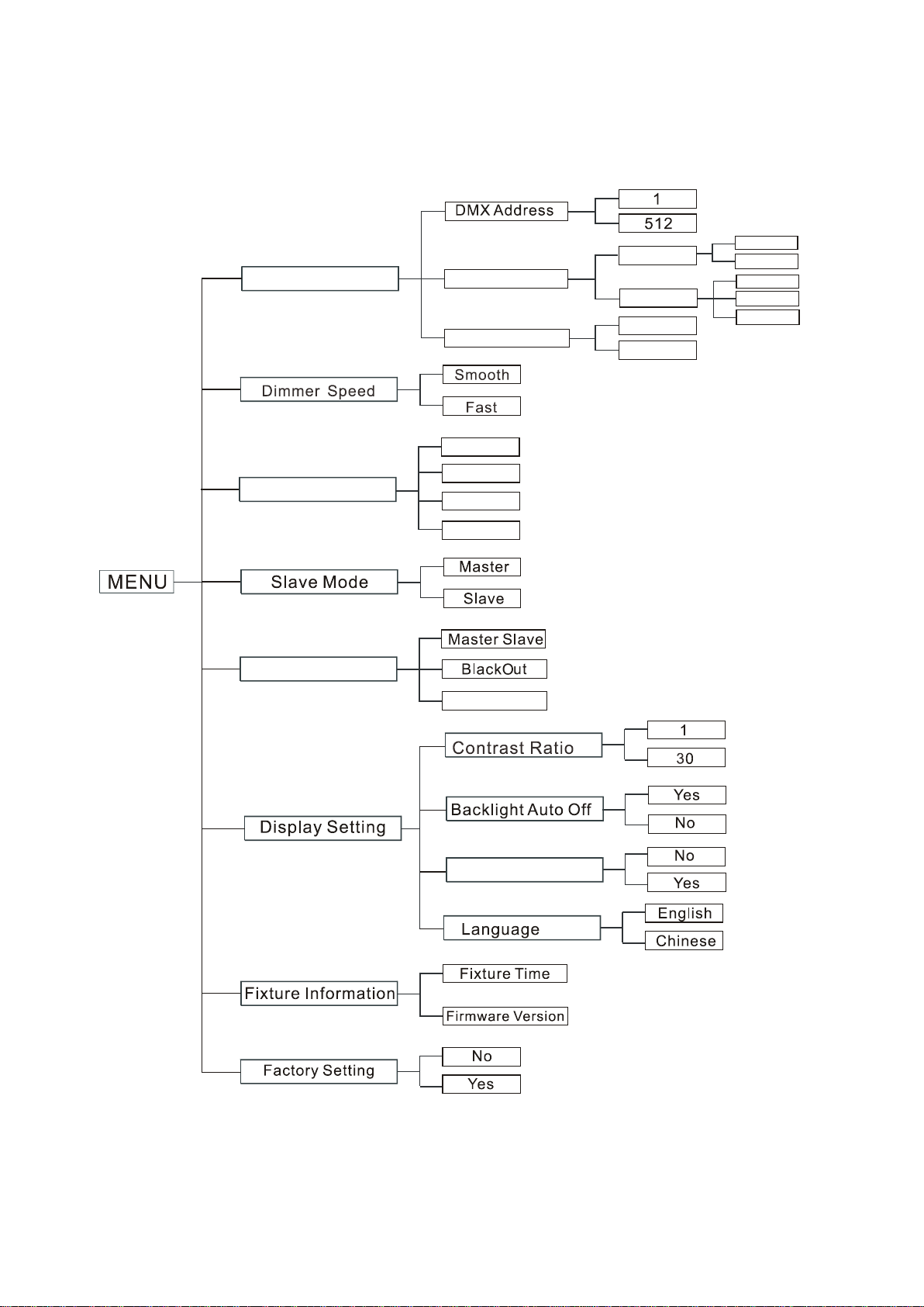
DMX Setting
Enter menu mode, select DMX Setting,press ENTER button to confirm, use UP/DOWN button to
select DMX Address, Art-Net Setup, Channel Mode.
DMX Address
Select DMX Address, press the ENTER button to confirm, the present address will blink on the
display. Use the UP and DOWN button to adjust the DMX address from 1to 512. Once the address
has been selected, press the ENTER button to save. Hold and press the MENU button about one
second or wait for one minute to exit the menu mode.
Art-Net Setup
Select Art-Net Setup, press the ENTER button to confirm, present mode will blink on the display.
Use the DOWN and UP button to select the Ethernet IP Setup or Art-Net Port Setup. Once the
mode has been selected, press the ENTER button to save. Hold and press the MENU button about
one second or wait for one minute to exit the menu mode.
Dimmer Speed
Select Dimmer Speed, press the ENTER button to confirm, present mode will blink on the display.
Use the DOWN and UP button to select the Smooth (dimmer speed smooth) or Fast(dimmer
speed fast) mode. Once the mode has been selected, press the ENTER button to save. Hold and
press the MENU button about one second or wait for one minute to exit the menu mode.
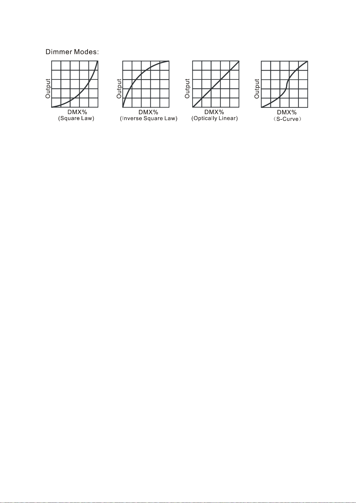
Dimmer Curve
To select Dimmer Curve, press the ENTER button to show the DIMMER CURVE on the display, use
the UP/DOWN button to select Linear Curve, S q Law Curve, nvert S q Law Curve or S Curve. Once
selected, press the ENTER button to store. Press the MENU button back to the last menu or let the
unit idle one minute to exit menu mode.
8D