ACME EMP370 Assembly instructions

EMP 370/371 Reference Manual
User’s Manual
1
EMP370/371 User Reference Manual
Revision 1.2 (080717)

EMP 370/371 Reference Manual
User’s Manual
2
C
Ch
ha
as
ss
si
is
s
S
Sp
pe
ec
ci
if
fi
ic
ca
at
ti
io
on
n
o
of
f
E
EM
MP
P3
37
70
0/
/3
37
71
1
Chassis
External Chassis
Aluminum/Aluminum Extrusion
Internal Chassis
Aluminum alloy frame
Form Factor
ATX (370), Passive Backplane (371)
Display
LCD
17" SXGA
Resolution
17” 1280 x 1024
Color
16M colors
Integrated Peripherals
Speaker
2x
Amplified Board
2x 2 Watt
Cooling Fan
2x 120mm
Open Bay
3.5" Drive Bay
1x
5.25” Drive Bay
2x
Slim DVD
1x
Expansion Slot
Available Slot
7x Slot (370), 10x Slot (371)
1x I/O (370)
Input Peripheral
Keyboard
105-Key Cherry Switch Keyboard
Pointing Device
Integrated TouchPad
Environmental Specification EMP 370/371
Environmental
Specification
Operating Temp
0°C - 50°C
Relative Humidity
20-80% (non-condensing)
Shock
10G operating, all axes
Vibration
1.25G @ 10-100Hz operating, all axes
Compliance
CE & FCC
Power
Power supply
650W, PS2, 110VAC ~ 220VAC
Dimensions
H
346mm
W
433mm
D
229mm
Weight
Net weight
28.6LB (Chassis Weight)
Transport Case
Carrying Case
Padded carrying bag with wheels

EMP 370/371 Reference Manual
User’s Manual
3
Portable Case
EMP is one of our products designed to exceed your most demanding expectations. Its
expandable, portable and reliable configuration enhances not only the operational
performance but also addresses the most demanding business environments. EMP also
accommodates a standard size ATX motherboard, and passive backplane to fit various
technical requirements. But most importantly is that the EMP is a powerhouse that
contains dual processors that are traditionally found in bulky workstations. In fact, the EMP
comes with everything a large bulky workstation has such as built in LCD screen for super
sharp images, built-in amplified speakers, integrated keyboard/mouse, cooling fans,
internal card stabilizer; you name it. With its rugged infrastructure, EMP is manufactured
to fulfill the function in the most severe of working conditions, and at the same time provide
secure timely and elegant solutions. Furthermore, the EMP ingenious layout focuses on
space saving, and yet it provides unsurpassed power, more than any existing compatible
system. Undoubtedly, with its expandable configurations, EMP is the ultimate choice for
application and solution needs.
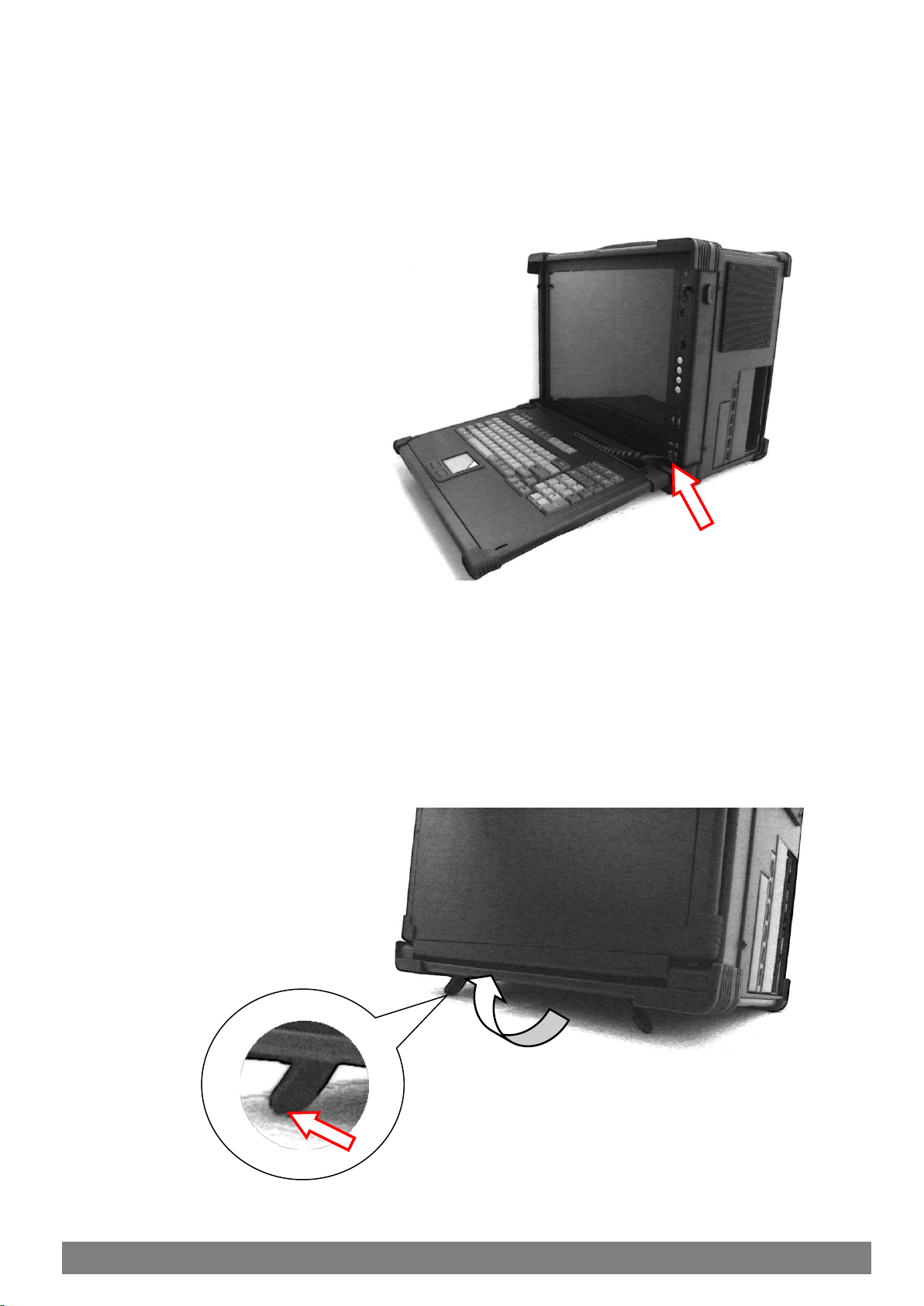
Instant Setup
Setting up is no hassle. EMP enables you to be up-and-running in seconds without
complicated setup. Our all-in-one design has integrated keyboard, mouse, and display into
a total package for your convenience.
LCD Display Information
The EMP has built-in high resolution LCD screens. With our engineering advancement,
LCD can be tilted and retracted fully effortlessly. The EMP370/371 is integrated with 17”
high brightness, high contrast and fast response LCD screens, and includes glass
protection or touch screen option.
Processor Information
The EMP system has been design to allow integration of the latest system board and
either single or multi processors. With revolutionary performance, ultra system
responsiveness, and energy-efficiency, there is no slowing down for multiple compute
intensive programs and downloads. The available GPU board can to install to provide the
latest precise and intensive graphic 3D rendering and image processing with exception
speed and accuracy.
Drive Configuration
The EMP has available bay for slim for DVD-RW drive for both single and dual layer
writing capability on reading. It has 1 empty 3.5” drive bay that can be expanded further
depending on your needs, and 2 empty 5.25” drive bay to add in removable tray or I/O
interface. Whether is speed or capacity requirement that you needs, the flexibility of
setting up different RAID configuration is available by your choosing.
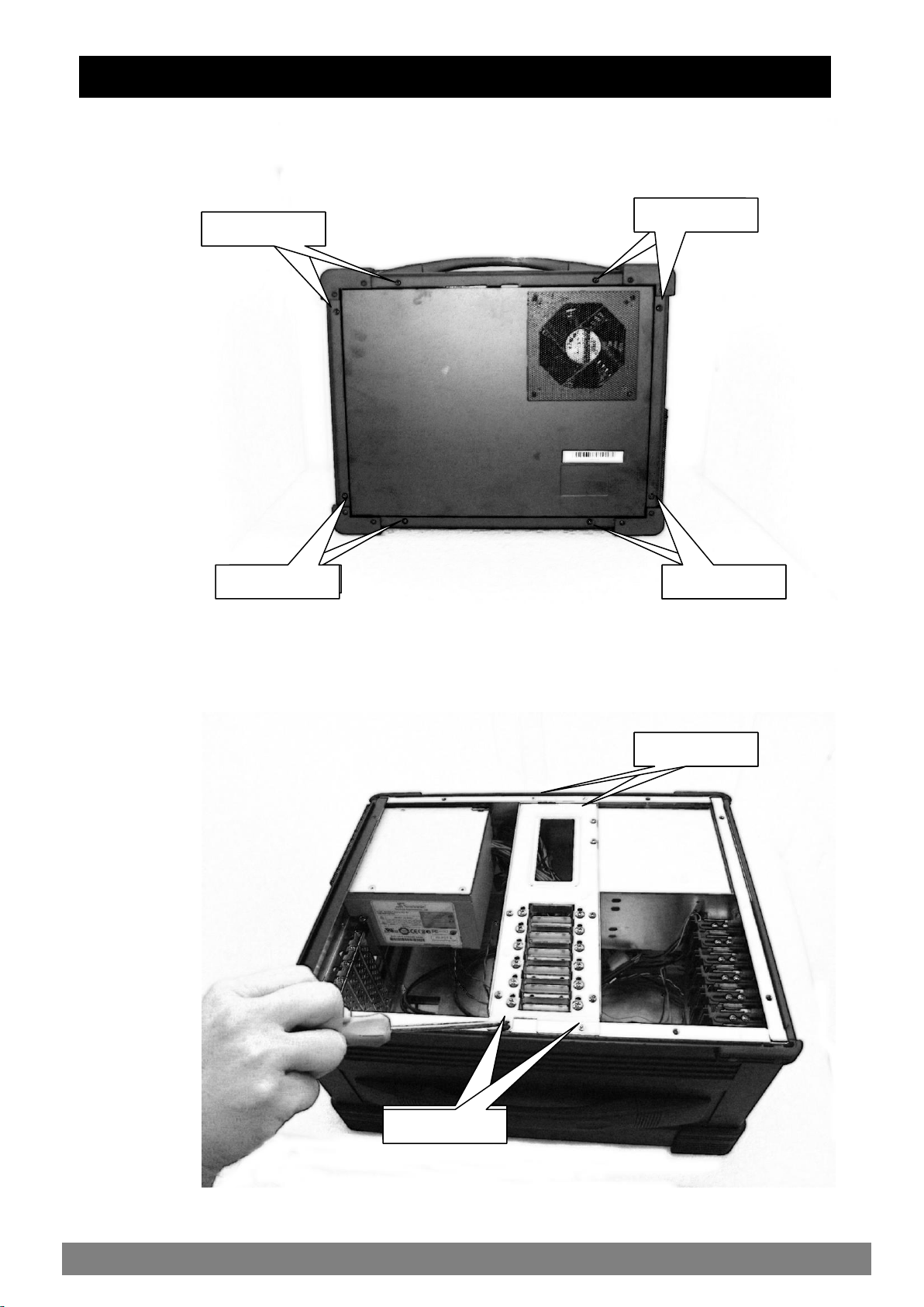
2.0 Getting Started
1.0 Introduction

EMP 370/371 Reference Manual
User’s Manual
4
2.1 Releasing Keyboard from main unit by pressing the 2 button located on each side of the
keyboard to release the locking mechanism, and then pull out the keyboard.
2.2 You have the option of leaving the keyboard attach to the chassis or they can be release
independently from the chassis by pushing the two lever inward to release the lock.
2.0 Operation Features of the EMP
Lift Up

EMP 370/371 Reference Manual
User’s Manual
5
2.3 Connect the keyboard/touchpad cable to the front bottom right corner of the chassis. Make
sure the pin direction is correct when inserting. **Keyboard can be close back without
disconnecting this plug.
2.4 You can flip the 2 feet located underneath the chassis outward to help create an angle for the
chassis for viewing comfort. Locate the feet and flip outward until click.
1
2

EMP 370/371 Reference Manual
User’s Manual
6
2.5 Connect the power cable outlet into the power supply unit in the main chassis on the left.
*370 model shown, 371 model location is similar.
2.6 Press the power button in the front right panel of the chassis to power up the unit.
Insert Power Cord
Press Once to
Power On

EMP 370/371 Reference Manual
User’s Manual
7
2.7 Right front panel of chassis have access to indicator light, reset, power and USB port.
2.8 Access the expansion slot on the left side of the chassis. The 370 version will have 7 slots
available and the 371 model will have 10 slots available. * 371 model shown in illustration.
PWR LED
HDD LED
Reset Button
LCD On/Off Button
Power Button
USB Ports
LCD OSD Button

EMP 370/371 Reference Manual
User’s Manual
8
2.9 Two cooling fan are located on the chassis, one located on the rear and another on right side.
2.10 Access the system board I/O panel on the bottom left side of the chassis. The I/O panel is
only available on the 370 model where ATX system board is used.

EMP 370/371 Reference Manual
User’s Manual
9
2.11Acces the optical drive and any removable drive kit or drive mounting device on the right hand
side of the chassis.
2.12 There are four buttons located on the right side of the LCD. Adjust LCD OSD to match the
display to your video board via the OSD button located on right side of the LCD panel. Press
the MENU button to bring the on screen menu out and then follow instructions. Press the
UP/DOWN button to scroll through the menu and press the SELECT button to enter the
selected item. And UP/DOWN button to adjust value as necessary.
3.5” Drive
Mounting
OSD Buttons:
MENU
SELECT
UP
DOWN
5.25” Drive
mounting
Slim DVD
Mounting

EMP 370/371 Reference Manual
User’s Manual
10
**Be sure power cable is not connected to the system before proceeding
3.1 Unscrew the back cover screw to release it from the chassis.
3.2 Remove the 4 screws to remove the 2 stabilizer bars from the chassis to access into the
internal chassis.
3.0 Internal Hardware Access
Unscrew
1
Unscrew
Unscrew
Unscrew
Unscrew
Unscrew
Unscrew
Unscrew
Unscrew
UnscrewUnscrew

EMP 370/371 Reference Manual
User’s Manual
11
3.3 Remove the left side cover plate by unscrewing the 3 hex screws on the left side.
3.4 Removing the left side cover door by lifting out.
Unscrew
Unscrew
Unscrew

EMP 370/371 Reference Manual
User’s Manual
12
3.5 Remove the 4 screws on the chassis to remove the power supply unit form the chassis.
3.6 Remove the right side cover plate by unscrewing the 2 hex screws on the right side.
Unscrew
Unscrew
Unscrew
Unscrew
Unscrew
Unscrew

EMP 370/371 Reference Manual
User’s Manual
13
3.7 Remove the right side cover door by lifting out.
3.8 Remove the 2 mounting screw and slide the drive cage outward from its rail.
UnscrewUnscrew

EMP 370/371 Reference Manual
User’s Manual
14
3.9 Install the motherboard I/O shield plate (370 only) on the left side of the chassis opening and
the proper standoff mounting according to the system board mounting opening.
3.10 Remove the 4 screws for holder of the internal removable tray assembly.
Unscrew
I/O Plate
Location
Unscrew
Standoff Mount
3.5” Device
Screw
5.25” Device
Screws
Slim DVD

EMP 370/371 Reference Manual
User’s Manual
15
3.11 You can remove the 3.5” attachment alone by removing the bottom assembly. The Slim
DVD can also be optional.
3.12 You can install all devices and configuration of your choices in different combinations.
UnscrewUnscrew

EMP 370/371 Reference Manual
User’s Manual
16
3.13 Install your add-in card as necessary and secure tightly.
3.14 Fit the VGA or DVI cable through the top the slot first prior to installation display card and
connect the header.
Fit Cable
Through

EMP 370/371 Reference Manual
User’s Manual
17
You can use the built-in DVD-RW drive to load additional applications software into the system.
Available medium from USB or download can also be possible. The system is pre-loaded with
Windows operating system, additional multiple O/S can be added or replaced.
DOS Boot up: DOS boot up requires you to have a version of the DOS installed on hard disk
drive or floppy. Depending on the execution sequence you have set in the batch file, you will
usually get a DOS prompt after loading.
Window Boot up: Windows boot up requires you to have Windows installed in the hard disk drive.
During Windows boot up, you will see a sequence of access to your hard disk drive which will
eventually take you into a graphical user interface environment.
Other O/S description: Many other operating systems are available in the market, such as Linux,
Windows, Solaris and DOS. These operating systems will behave differently and you should
react accordingly.
4.0 Software Installation

EMP 370/371 Reference Manual
User’s Manual
18
5.1 Handling of EMP:
You should always make sure the keyboard assembly is properly closed onto the EMP before
transporting it. This will ensure you do not loose the keyboard as well as protecting the LCD
screen. You may transport the portable in its carrying case, or you can carry the EMP on its
handle located on top of the machine. The handle is located securely to the strongest part of the
machine, and distributes the load of the EMP evenly as to allow easy carriage and proper
balance.
5.2 Handling of Cable:
All cable should be treated with care. Do not over extend any cable and this could result in
breakage internally in the cable. It is essential that cable with its plug be handled in the proper
manner without force.
5.3 Handling of LCD:
Do not use any abrasive material to scratch the LCD screen, as they can leave marks on the
surface. Do not apply any pressure to the surface of the LCD screen either with objects or hands;
this will ensure that the screen do not suffer from internal damage or cracks.
5.4 Handling of Power:
Always make sure the power cord is in top condition before using them with the EMP. Make sure
your power source is reliable and of proper standard. The EMP power supply is capable of
handling 100-240V and 50-60Hz. Do not use the EMP on an already overloaded circuit.
5.5 Handling of K/B:
The keyboard is essential in that it helps protect the LCD during transportation. You should
always watch for spill liquid or small objects from entering the keyboard. And the touch pad
surface should be kept dry and clean for proper usage.
5.6 Cleaning LCD:
1. Do not use cleaner that contain alcohol.
2. Do not use cloths that could be abrasive to the surface of the LCD.
3. Always gently wipe the LCD surface when cleaning.
5.7 Cleaning K/B:
1. Do not spill any liquid on to the keyboard.
2. Do not drop particle into the spacing between keys.
3. Using a compress air cleaner, you can remove the dust built-up within.
5.8 Cleaning Fan Filter:
1. Remove the filter from its housing.
2. Use a compress air cleaner to blow off the dust from the filter.
3. If necessary, you can wash the filter material, but do remember to dry it first.
5.0 Maintenance

EMP 370/371 Reference Manual
User’s Manual
19
6.1 Installation problem:
1. Normally problem with a fail start up is due to installation problem.
2. Double check all the peripheral cards or items you have added to the EMP.
3. Are all the items seated properly?
4. Are all the cables connected back to its original or correct position?
5. Are the items you have added compatible?
6. Before you check for these, turn the computer off and unplug the power cord.
7. Check for 1 thru 5 and then re-power up the computer.
8. Remove all items that were added and re-try system power up.
9. If the system starts now, try inserting 1 new item in at a time and try powering up.
10. Repeat this step until you get the desired result.
6.2 BIOS Beep Code:
The BIOS beep code indicates error in system initialization. The BIOS of the system board
will associate with video and memory error. Please check your video card is properly seated and
your memory is installed properly.
6.3 System Fails to power up:
1. Check you power connection first.
2. Check the main power switch is in the ON positions (I).
3. Press the power button located in front of the machine.
6.4 No display (LCD):
1. Check all the proper power up procedure has been taken.
2. Hook up an external CRT to the VGA port, to check if video is present.
3. If video is present on external CRT, check the internal LCD cable connection.
4. Or check your VGA setting using a CRT to make sure LCD video is enabled.
5. If there is no video on external, check make sure everything is seated properly.
6. If everything is seated properly and still no video, call us for further assistance.
6.5 External CRT no display:
1. Check to see if you have internal LCD video.
2. Check if your CRT is functioning properly.
3. Check your VGA setting to make sure external video is enabled.
6.6 Keyboard fails:
1. Make sure the keyboard plug is inserted completely into the portable.
2. Make sure you do not have another keyboard connected to the side I/O PS/2 port.
6.7 TOUCHPAD fails:
1. Make sure the keyboard plug is inserted completely into the portable.
2. If you have an external mouse hook up on the side I/O port, the touch pad will not function
simultaneously.
3. If your operating system requires and does not load the mouse driver automatically, make
sure you have the proper mouse driver loaded.
6.8 DVD-ROM fails:
1. Make sure the CD/DVD is readable.
2. If DVD-ROM fails to be recognized during POST, check internal cable fit.
6.0 Problem Solving

EMP 370/371 Reference Manual
User’s Manual
20
Package Content
Description
Qty
1
User’s Manual
User’s Reference Guide
1
2
ESD Bag
ESD Bag for additional
packaging
1
3
110 Power Cord
220 Power Cord (Option)
110 Power Cord
220 Power Cord (Option)
1
4
Screw Pack
Screw Pack (stabilizer)
1
5
Stabilizer Supports Pack
Additional clip for card holder to
secure add-in card
1
6
EMP370/371 System
Main system unit chassis
1
7
Carrying Bag
Tow bag with wheel
1
7.0 Standard SKD Accessory Kits
This manual suits for next models
1
Table of contents
Other ACME Laptop manuals