ACO FUNKI Egebjerg MASTER Chain User manual

09-11-2018 · ACO FUNKI · Tlf. 97119600 · www.acofunki.com
Egebjerg MASTER Chain® - feeding system
84.001 - UK

09-11-2018 · ACO FUNKI · Tlf. 97119600 · www.acofunki.com Page 2
MASTER CHAIN®FEEDING SYSTEM
Contents
Preface ............................................................................... 3
Introduction ....................................................................... 3
Safety ................................................................................ 4
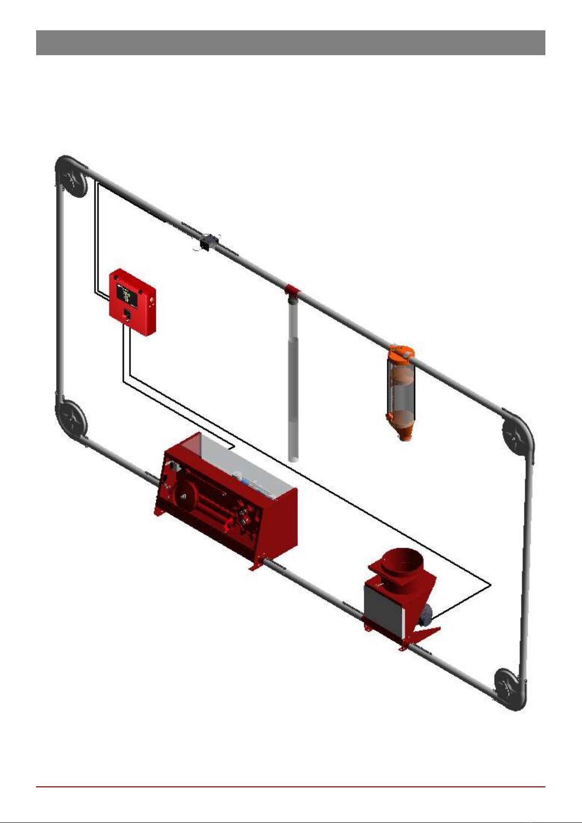
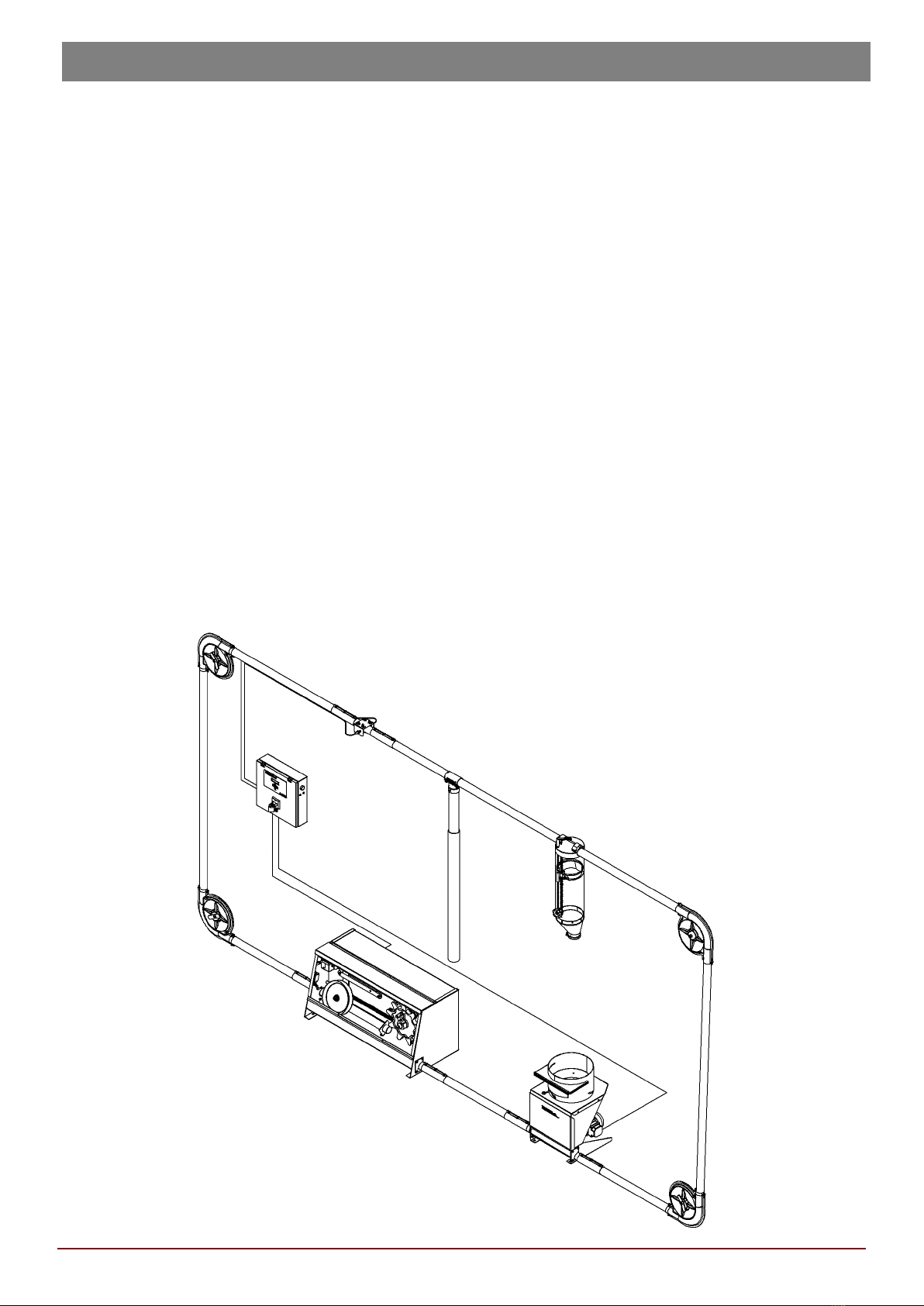
Planning the location of the feeding system ...................... 5
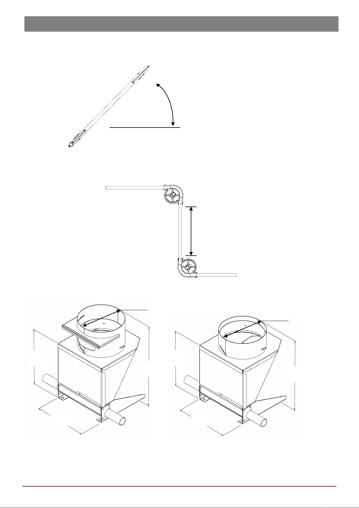
Installation height ............................................................. 5
Bends ................................................................................. 6
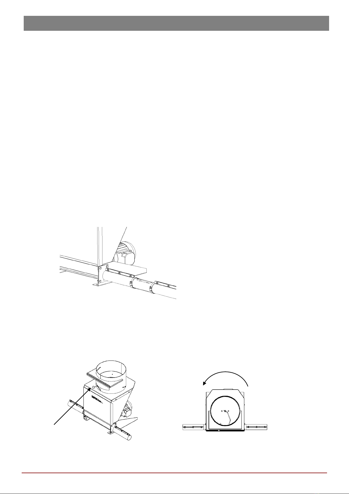
Loading hopper .................................................................... 6
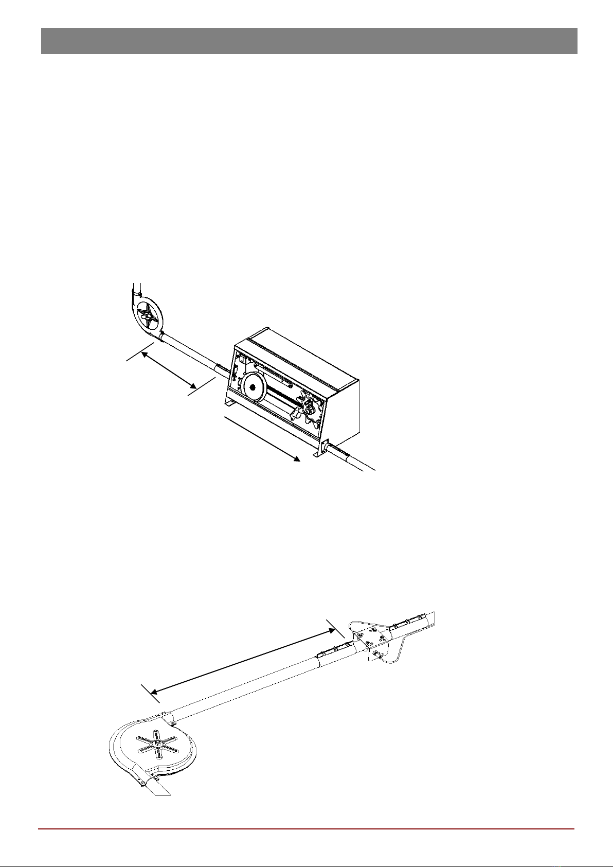
Drive unit ............................................................................ 7
Sensor switch ...................................................................... 7
Assembly ........................................................................... 8
Loading hopper .................................................................... 8
Adjustment ......................................................................... 8
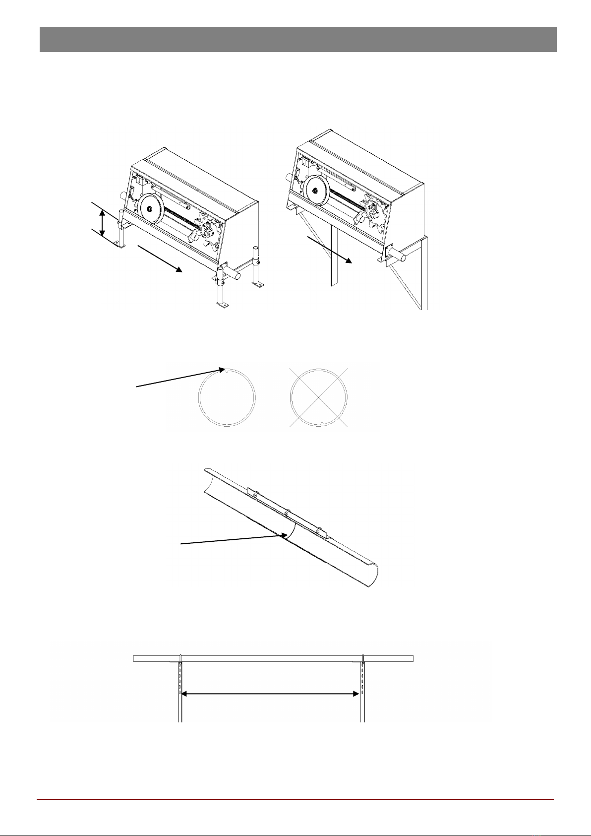
Drive unit ............................................................................ 9
Feed pipes .......................................................................... 9
Splicing sleeves ..................................................................10
Bends ................................................................................10
Feed outlet .........................................................................10
Plastic feed dispensers .........................................................11
Sensor switch .....................................................................11
Feed wire ...........................................................................12
Feed chain .........................................................................13
Opening system for plastic feed dispensers ............................14
Mounting the opening system ...............................................14
Adjusting the opening device ................................................15
Technical data ...................................................................16
Drive unit ...........................................................................16
Accessories ........................................................................18
Loading hopper ...................................................................18
Opening motor ...................................................................20
Maintenance ......................................................................21
Troubleshooting .................................................................22

Page 3 09-11-2018 · ACO FUNKI · Tlf. 97119600 · www.acofunki.com
FEEDING SYSTEM MASTER CHAIN®
Preface
Thank you for selecting Egebjerg’s MASTER Chainmechanic feeding system.
The feeding system comprises a number of quality products that, combined correctly, gives you a system
characterised by great operating efficiency and a long working life. To ensure the greatest possible benefit of your
new feeding system in the years to come, please read this manual and follow the instructions given carefully.
Should you have any questions once you have read the manual, place contact one of our service employees on
Introduction
Egebjerg Master Chainis a modern dry feed dispenser system developed to transport animal meal or pelleted
feed with a diameter of up to 5 mm and a length of 10 mm from a silo to a number of feeding locations in the pig
barn.
The feed is transported in a galvanised steel piping system. The feed is transported via a chain or wire fitted with
cast plastic carriers that drives the feed to the feeding locations.
A computer-controlled drive unit drives the chain or wire. Once all feeding locations are full, a sensor switch
signals to the computer that the feeding system has been filled and must be stopped. The sensor switch is placed
after the last feeding location.
The drive unit is equipped with mechanical and electronic fuses against overload.
The loading system is placed below the silo, and doses the feed evenly and precisely into the piping system. Thus,
the loading hopper is indirectly decisive for the operating efficiency of the system and the working life of the feed
wire or feed chain.

09-11-2018 · ACO FUNKI · Tlf. 97119600 · www.acofunki.com Page 4
MASTER CHAIN®FEEDING SYSTEM
Safety
-Switch off power to the system during service or inspection.
-Lock the main switch on the control unit.
It is dangerous to service or inspect the system without cutting off the power first. The system may
start automatically or another person may start it without knowing that the system is being serviced.
Therefore, do not dismantle the system or dismount screening, lids and covers without cutting off and
locking the main switch.
Never place objects or parts of the body under a feed outlet or other openings to clean away feed
remains or similar, without cutting off power and locking the system first. There is a great risk of being
injured if the system starts up by mistake.
Mounting and repairs of electric installations only to be performed by a trained electrician.

Page 5 09-11-2018 · ACO FUNKI · Tlf. 97119600 · www.acofunki.com
FEEDING SYSTEM MASTER CHAIN®
Planning the location of the feeding system
Before initiating installation of the feeding system it is essential to plan in detail the layout through the
pig barn, including the location of the individual components.
The longest working life is obtained by installing the feeding system with the lowest possible amount of
bends.
Please consider the following when planning the piping layout:
• Floor-to-ceiling height, windows, doors and gates that it must be possible to open.
• Steel rafters or other objects protruding from the walls or hanging down from the ceiling.
• Ventilating plants, posts or other piping that the feeding system passes.
• The possibility of suspending, supporting or in other ways fixing the feed pipe.
Installation height
Normally, the feed pipe should be installed at a height of 2.2-2.4 metres.
Please note that it must be possible for people working in the pig barn to open and close the shutters
in the feed outlets on the feed pipe. (In pig barns using Egebjerg’s KS dispensers, the feed pipe is
installed at a height of 2 metres.)
Feeding systems using plastic feed dispensers must have free space of 15 centimetres from the
underside of the feed pipe to ceiling, rafter or similar to make room for installation of wire and fittings
for central opening.
Rotating direction

09-11-2018 · ACO FUNKI · Tlf. 97119600 · www.acofunki.com Page 6
MASTER CHAIN®FEEDING SYSTEM
Bends
Where the feed mechanism changes to another level, the feed must be lifted via piping at a 45-degree slope, if
possible. This reduces the risk of segregation while at the same time causing minimum strain on the system. The
return pipe, on the other hand, may be lead down vertically.
Z piping and two bends, assembled at a right angle, are to be avoided wherever possible. This type of
installation causes the transport wire to twist and applies unnecessary strain on the system. If this
type of wiring is unavoidable, the distance between the bends must be a minimum of 2 metres.
Loading hopper
Place the loading hopper below the feed silo.
45˚
Min. 2 meter
365
365
515
582
400
400
Ø280
With gate
Without gate
Ø280

Page 7 09-11-2018 · ACO FUNKI · Tlf. 97119600 · www.acofunki.com
FEEDING SYSTEM MASTER CHAIN®
Drive unit
The optimum location of the drive unit is between the last feed outlet and the loading hopper. See
rotating direction on the illustration.
The drive unit may be installed:
-directly on the floor
-4-20 cm above the floor on adjustable legs
-on wall-mounted shelf brackets
Egebjerg’s drive unit has been designed to allow feed to pass through. Consequently, the drive unit
may be placed at the middle of the feeding system if other locations are not possible. This type of
installation, however, increases the risk of feed segregation, and should therefore be avoided.
The drive unit works best when there is a long piece of straight piping before the drive unit inlet.
In chain systems there must be a straight piece of piping measuring at least 3 metres from the drive
unit inlet to the bend before it.
Sensor switch
Place the sensor switch after the last feed outlet. Place the sensor a minimum of 1.5 metres from the
nearest feed bend.
Min 3 meter.
Min. 1,5 meter.
Rotating direction

09-11-2018 · ACO FUNKI · Tlf. 97119600 · www.acofunki.com Page 8
MASTER CHAIN®FEEDING SYSTEM
Assembly
Loading hopper
Place the loading hopper below the silo. The station may be attached directly to the silo using bolts or attached via
a funnel installed on top of the loading hopper.
The loading hopper is supplied with or without gate. If the silo does not have a gate we recommend you select a
loading hopper with a gate.
If you use a funnel and your silo has a gate, the top edge of the funnel must be lower than the silo gate, allowing
it to open freely.
In outdoor installations we recommend the loading hopper to be protected with a cover to prevent water
percolation.
Attach the loading hopper directly to the floor using coach screws or mount on adjupig barn legs to adapt the
height to the silo.
Mount the inspection pipe after the outlet pipe on the loading hopper using a splicing sleeve. Place the inspection
pipe so that the oblong hole is horizontal, and covered by the slotted plastic tube. Attach the plastic tube to the
inspection pipe using two clamps.
The inspection pipe allows the user to see how full the feed pipe is, thus checking the adjustment of the loading
hopper.
Adjustment
The loading hopper is fitted with a motor that drives a horizontally rotating arm via an axle. The rotation of the
arm causes continuous administering of feed to the feeding system to occur, thus preventing overload and
blocking. The feed quantity may be adjusted using a turnable dosing gate.
Considering the load and operating reliability of the system, we recommend the feed quantity to be set so that the
feed pipe is approximately half full. The feed pipe must never be more than two thirds full.
Dosing Gate
Rotating direction

Page 9 09-11-2018 · ACO FUNKI · Tlf. 97119600 · www.acofunki.com
FEEDING SYSTEM MASTER CHAIN®
Drive unit
The optimum location of the drive unit is between the last feed outlet and the loading hopper. See rotating
direction on the illustration.
The drive unit may be installed on the floor, raised above the floor on adjustable legs (4-20 cm), or on the wall
using shelf brackets.
Feed pipes
The feed pipes are galvanised on the inside and outside. Inside the pipes is a little welding seam that must face
upwards when installing the pipes. This prevents unnecessary wear of the carriers on the feed wire or feed chain.
If required, shorten the pipes using a hacksaw or an angle grinder. Saw the pipes at a right angle, allowing for a
tight connection in the splicing sleeves. Grind the pipes on the inside and the outside, and remove any chips from
the pipes before installation.
The feed pipes must be supported every 3 metres, and attach to the ceiling, wall or a post using fittings. The
pipes must be fixed tightly so that it is not possible move them horizontally or vertically. It is important not to
force or bend the feed pipes around obstacles. Use a guide to check whether the piping is straight. If the feed
pipes are not mounted correctly, the carriers are subjected to unnecessary wear on the inside of the pipes,
causing damage to both pipes and carriers.
If the feed pipes are lead from a warm pig barn outdoors or through a non-insulated room, we recommend the
pipes to be isolated through the cold area to prevent the feed from coating inside the pipes as a result of
condensation.
4-20 cm.
Max. 3 meter.
Welding
Avoid edges that the carriers may hit
Rotating direction
Rotating direction

09-11-2018 · ACO FUNKI · Tlf. 97119600 · www.acofunki.com Page 10
MASTER CHAIN®FEEDING SYSTEM
Splicing sleeves
Mount splicing sleeves with the screws pointing upwards to prevent feed loss. Where joints are made
outdoors, the splicing sleeve must be turned, placing the screws on the side of the tube to avoid water
percolation. If the joints are required to be completely tight, tighten with silicone.
Bends
Feed bends are mounted so that the cover with the wing screw points downward, and the direction indication on
the inner wheel is in accordance with the transport direction of the feed.(60 mm inner wheel does not have a
predetermined rotating direction). If the rotating direction on the corner wheel is incorrect, too much resistance
will build up in the system over time, and the system may subsequently break down.
Without / With
Rotating direction
When mounting the feed pipes, make sure to push them all the way to the stop in the corners.
Feed outlet
When the feed system has been assembled, mark up for outlet holes where feed outlets or feed dispensers are to
be placed. Drill the outlet holes in the feed pipe using a tapered drill. See the size in the table.
Deburr the holes in the feed pipe on the inside and outside.
Mount the top cap of the feed outlet on top of the feed pipe, then tighten the feed outlet using a Parker’s
screwdriver.
Note!
Always tighten using a hand-held screwdriver, allowing the gate to move freely back and forth.
Do NOT use a clamping device or drilling machine
Feed pipes A meassure B meassure
38 mm 25 50
50 mm 35 60
60 mm 42 60

Page 11 09-11-2018 · ACO FUNKI · Tlf. 97119600 · www.acofunki.com
FEEDING SYSTEM MASTER CHAIN®
Plastic feed dispensers
Plastic feed dispenser are delivered pre-mounted and ready for use after mounting on the feeding system.
Remove the two clamp straps, then remove the adapter.
Split the adapter into two pieces, then mount around the feed pipe. Place the gate in the trail on the upper part of
the feed box, place it on the feeding system around the adapter, then remount the two clamp straps.
There is no adapter on 60 mm feed pipes. Mount the feed box directly on the feed pipe. The lower part of the feed
pipe may be mounted in four different positions, allowing the outlet to turn.
Sensor switch
Place the sensor between the last feed outlet and the loading hopper, however, not closer than 1.5 metres from a
bend.
The feed pipe must be supported immediately before or after the place where the sensor is located. If the feed
pipe is curved, feed will be left in the pipe that the carriers cannot remove. This will disturb the signal and the
functioning of the sensor.
Mount the sensor on a transparent plastic tube using the appropriate fitting. (see fig. A)
Place the plastic tube on the feeding system using two splicing sleeves.
If several sets of switch sensors are placed close to each other in the same housing section, it is important to
locate the transmitters so that their signals are sent in opposite directions (see fig. A)
The transmitter is marked with red. The ICS T O TP 5/receiver with yellow ICS R 001 TP 5
Transmitter (red)
Receiver (yellow)

09-11-2018 · ACO FUNKI · Tlf. 97119600 · www.acofunki.com Page 12
MASTER CHAIN®FEEDING SYSTEM
Feed wire
Demount the transparent drive unit front plate and covers on all feed bends. Lead the wire through the drive unit
outlet to the first corner or to the loading hopper. Continue leading the wire from bend to bend through the entire
system all the way to the drive unit. Remember to turn the feed wire roll while unwinding the wire to prevent the
formation of loops. Also remember to check the rotating direction on all bend wheels.
Once the wire has been taken all the way back to the drive unit, lead it around the drive wheel and then around
the tightening wheel. Then, tighten the wire until the tightening wheel has travelled ¾ of its total to the right.
Indicate the place where the wire is to be shortened.
Saw away the plastic plate where the wire is to be shortened. Carefully saw the plate from both sides along the
wire until the plastic plate has almost been sawed through. Carefully wriggle the two halves apart. Take care not
to damage the individual wire threads. Should this happen anyway, you will have to saw off another plate. Cut the
wire nicely using a wire cutter. The wire has been wound into shape and will not unwind when cut. Collect the
wire. It is important that all wire threads are intact and placed nicely in the wire collector and that there are no
plastic residues where the wire joint is to be placed.
Place the wire around the drive wheel and tightening wheels again, and check that the wire collector does not
touch the drive wheel teeth.
Release the wire break switch by turning it clockwise. Mount the front plate on the drive unit and the covers on all
bend wheels.
Please note that the wire will stretch after a while. If necessary, readjust the length of the wire.
Feed chain
Demount the transparent drive unit front plate and covers on all feed bends.
Remove the feed chain from the bag and place it on a flat surface. Check that the chain does not twist (turn the
chain until all twists have been removed).
To pull the chain through the system, use a detector spring or a strong piece of wire that is as long as the longest
distance between the two feed bends on the entire feeding system.
Lead the wire through the drive unit outlet to the first corner or to the loading hopper. Secure the wire to the feed
chain and pull the chain through the feed pipe using the wire. Continue leading the wire from bend to bend
through the entire system, thus leading the chain all the way to the drive unit.
Rotating direction

Page 13 09-11-2018 · ACO FUNKI · Tlf. 97119600 · www.acofunki.com
FEEDING SYSTEM MASTER CHAIN®
It is important to check that the chain does not twist while being pulled through the system. Once the
wire is back at the drive unit, lead it around the drive wheel and then around the tightening wheel.
Then, tighten the wire until the tightening wheel has travelled ¾ of its total to the right. Indicate the place where
the wire is to be shortened. Cut the wire in a link without carrier, and collect the chain using a joint link. Then,
place the chain around the drive wheel and tightening wheel.
Release the chain break switch by turning it clockwise. Mount the front plate on the drive unit and the covers on
all bend wheels.
Please note that the chain will stretch after a while. If necessary, readjust the length of the chain.
OK
Wrong
Wrong

09-11-2018 · ACO FUNKI · Tlf. 97119600 · www.acofunki.com Page 14
MASTER CHAIN®FEEDING SYSTEM
Opening system for plastic feed dispensers
The opening system allows you to open several feed boxed from a central location in the pig barn.
The opening device consists of a piano thread connected to the release arm on each feed box.
Tighten the piano thread using a spring and a wire strainer, ensuring feed dispensers to be uniform and
completely open when feeding takes place.
The opening device may be manual or automatic via the control to the feeding system.
Where a manual opening device is used: lower the lever to pull back the spring on each individual feed box,
allowing the feed to fall freely through the feed pipe.
To close, lift the same lever and lock, thus closing all feed dispensers.
The same principle is used for the automatic opening device. However, a motor is used to tighten and release the
piano thread.
Mounting the opening system
1. Where a manual opening system is used, we recommend a maximum of 35 feed dispensers on the same
opening unit.
2. Where an automatic opening system is used, we recommend a maximum of 90 dispensers on each motor
unit.
Begin by making a loop at the end of the 2 mm piano thread.
Pull the piano thread through the tightening screws on all opening arms from wall to wall.
Mount a wall bracket. Attach the spring that pulls back the piano thread to the bracket.
Manuel
release
Automatic
release
Release arm
Spring
Wall
bracket
Feed
dispenser

Page 15 09-11-2018 · ACO FUNKI · Tlf. 97119600 · www.acofunki.com
FEEDING SYSTEM MASTER CHAIN®
Mount a wire roll on the opposite wall.
Tighten the piano thread until the spring is approx. 50% stretched out. Cut off the piano thread approx. 25 cm
before the wire roll.
Make a loop at the end of the thread. The piano thread is now ready for use.
Pull a 3 mm wire from the opening device through the wire roll and approx. 15-20 cm after the wire roll.
Make a loop at either end of the wire. Attach it to the piano thread using a wire strainer and the opening device
using a shackle.
Now connect the system: end wall with bracket –spring –piano thread –wire strainer –wire –wire roll –opening
device.
Where several lines are used, join the wire along the wall in front of the opening device. Take care to apply
uniform tension on each line.
Adjusting the opening device
Set the opening device in position closed!
The spring on each line should be pre-stretched to approx. 50%.
Adjust the lines using the wire strainers.
Then, tighten the screw on the individual opening arm, putting them in position closed on each feed box.
Test by putting the opening device in position open.
Now, all feed dispensers must be open and the spring must keep the piano thread tight.
The spring should be tense in position open!
Tip!
The piano thread and wire will stretch slightly after a while. Check that all feed dispensers are opened completely
when the opening system is in position open.
2 mm pianothread
Wirestrainer
3 mm wire
Min. 25 cm.
Min. 25 cm.
Closed
Open
Open
Closed

09-11-2018 · ACO FUNKI · Tlf. 97119600 · www.acofunki.com Page 16
MASTER CHAIN®FEEDING SYSTEM
Technical data
Drive unit
Type 85005 85006 84955 84956 84900
No. Drive Wire 38 mm Chain 38 mm Wire 50 mm Chain 50 mm Chain 60 mm
Amount of feed per hour 400 kg. 400 kg. 700 kg. 700 kg. 1000 kg.
Metres per minute 20.8 23 21.1 23.4 23.4
1 Dispenser 87160 87160 87160 87160 87160
2 Motor 83500 83500 83505 83505 83505
Revs. per min. 1380 1380 1400 1400 1400
kw 0.75 0.75 1.5 1.5 1.5
Ah 2.2 2.2 3.47 3.47 3.47
DIM A in mm 125 125 140 140 140
DIM B in mm 100 100 125 125 125
DIM C in mm 55 55 65 65 65
DIM D in mm 80 80 90 90 90
Axle, diam. in mm 19 19 24 24 24
3 Gear 83570 83570 83570 83570 83575
gearing = I 1:25 1:25 1:25 1:25 1:25
4 V-belt 83525 83525 83525 83525 83526
5 Belt wheel motor Ø 56
6 Lock belt wheel motor 83540 83540 83541 83541 83541
7 Belt wheel gear Ø 112
8 Lock belt wheel gear 83550 83550 83550 83550 83551
9 Axle gear 87365 87365 87365 87365 87360
10 Spline for axle gear 87367 87367 87367 87367 87368
11 Rear plate gear 87170 87170 87170 87170 87180
12 Bracket, motor
13 Bracket, gear
14 Axle, bracket
15 Wire break switch
16 Holder for wire break switch
17 Cover, switch
18 Inlet pipe 87200 87200 87210 87210 87220
19 Inlet pipe holder 87230 87230 87235 87235 87240
20 Outlet pipe 87600 87600 87610 87610 87620
21 Drive wheel 85071 85069 85071 85069 85069
22
Non-grease bearing, dr. wheel
87267 87271 87267 87271 87271
23 Carrier, drive wheel 87280 85086 87280 85086 85086
24 Fragment 85300 87325 85300 87325 87325
Ultimate strength 230 kg. 450 kg. 230 kg 450 kg. 450 kg.
25 Tight. wheel, bearing + axle 85033 85033 85033 85033 85027
Bearing, tight. wheel 86265 86265 86265 86265 86260
Axle, tight. wheel 86258 86258 86258 86258 86259
26 Holder, tightening wheel
27 Rod, tightening wheel
28 Spring, tightening wheel
29 Control lever, tight. wheel
30 Spacer, control lever
31 Arm for wire/chain break
32 Shielding, motor/gear
33 Shielding lock
34 Plastic front plate, drive unit
87262
87260
85038
87195
87190
87250
87257
85034
85039
87245
87350
87395
87255
87380
83530
83531
87385

Page 17 09-11-2018 · ACO FUNKI · Tlf. 97119600 · www.acofunki.com
FEEDING SYSTEM MASTER CHAIN®

09-11-2018 · ACO FUNKI · Tlf. 97119600 · www.acofunki.com Page 18
MASTER CHAIN®FEEDING SYSTEM
Accessories
Loading hopper
Type 85005 85006 84955 84956 84900
No. Drive Wire 38 mm Chain 38 mm Wire 50 mm Chain 50 mm Chain 60 mm
Chain/wire
Ultimate strength 1300kg 1300kg 1300kg
Diameter, carrier 29 mm 29 mm 37 mm 37 mm 43 mm
Distance, carrier 100 mm 92 mm 100 mm 92 mm 92 mm
Sensor switch, set with pipes 88865 88865 88860 88860 88855
Transmitter
Receiver
88831 ICS R 001 TP 5 YELLOW
88830 ICS T O TP 5 RED
Type With gate 84232 84242 84252
No. Pipe 38 mm 50 mm 60 mm
1Upper part, loading hopper with gate
2 Gate
3 Inspection plate
Type Without gate 84202 84212 84222
No. Pipe 38 mm 50 mm 60 mm
1 Upper part, loading hopper
4 Dispenser
5 Adjustment
6 Eye screw
7 Pipe stub 87600 87610 87620
8 Front plate, plastic
9 Feed remover
10 Axle, feed remover
11 Bearing for remover axle
12 Clamp
13 Coupling hose
14 Axle, gear motor
15 Cotter, axle gear motor
16 Gear motor
87465
87470
87480
87460
87650
87660
87655
87510
67192
85130
87475
87500
87440
87520
87430

Page 19 09-11-2018 · ACO FUNKI · Tlf. 97119600 · www.acofunki.com
FEEDING SYSTEM MASTER CHAIN®

09-11-2018 · ACO FUNKI · Tlf. 97119600 · www.acofunki.com Page 20
MASTER CHAIN®FEEDING SYSTEM
Opening motor
No. Type 88600
1 Gear motor 87485
2 Stop switch 87350
3 Bracket 88630
4 Axle 88645
5 Spline 8 x 7 88642
6 Protection plate 88660
7 Opening rod 88670
8 Bracket for stop switch 88680
9 Bracket for opening rod 88675
10 Shackle 88685
Table of contents
Other ACO FUNKI Farm Equipment manuals
Popular Farm Equipment manuals by other brands

CONCORD
CONCORD PRECISION SHANK DRILL Operator's manual

Dhollandia
Dhollandia DH-RPH 33 installation manual

AGKNX
AGKNX 400 Operation manual

Ventrac
Ventrac DG550 BALLPARK RENOVATOR Operator's manual

McFarlane
McFarlane INCITE 5100 Series Assembly manual

LOFTNESS
LOFTNESS GrainLogix XLB10 Owner's manual and parts book