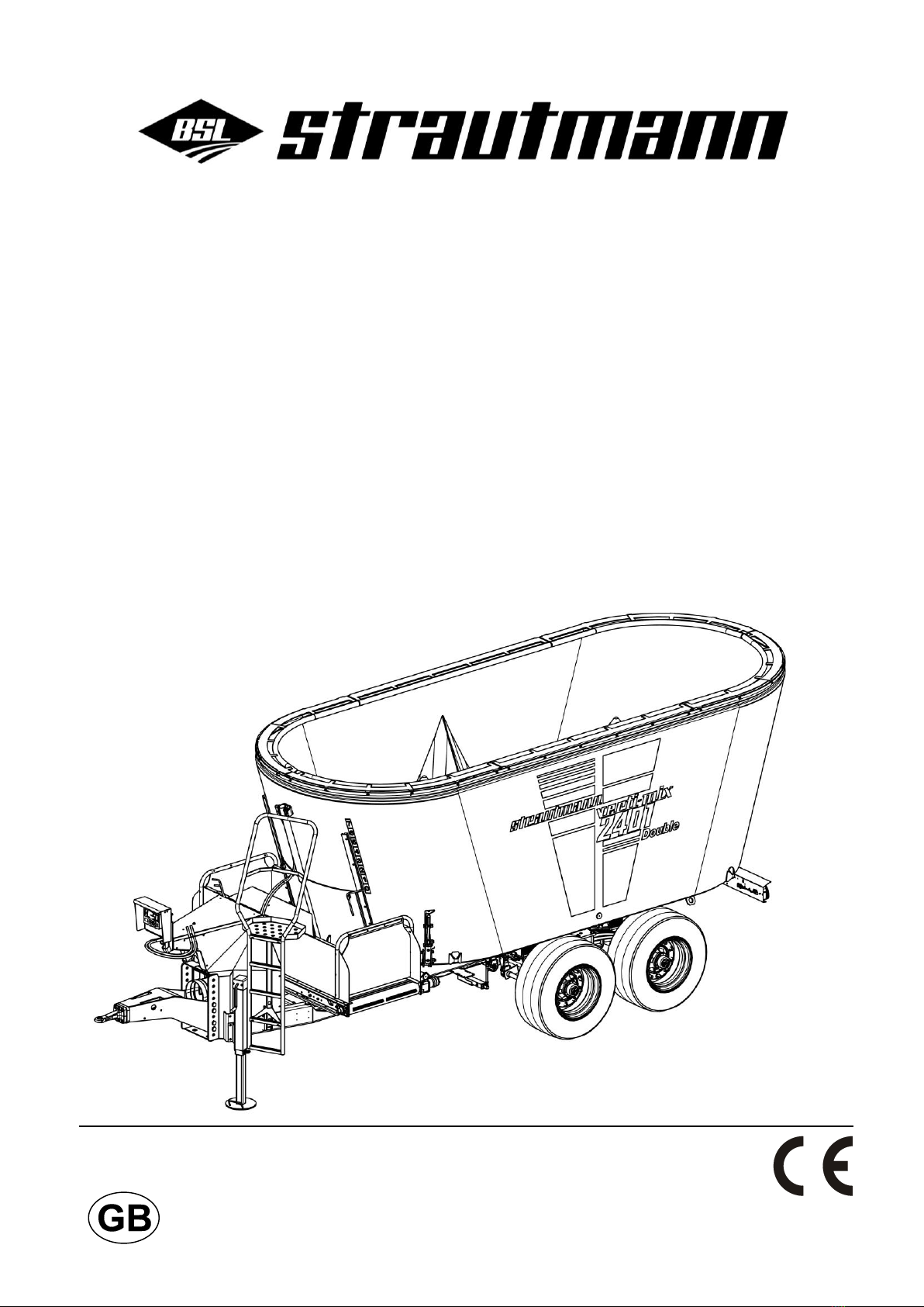
Verti-Mix 951-1651, Verti-Mix 951 L-1251 L, Verti-Mix 1501 D-2401 D 10.13
3.6.1 Warning signs ......................................................................................................... 43
3.6.2 Instruction signs ...................................................................................................... 47
3.6.3 Placing of warning and instruction signs................................................................. 49
3.7 Risks in case of non-observance of safety instructions and warning signs ........................ 50
4Loading and unloading .................................................................................... 51
4.1.1.1 Verti-Mix ................................................................................................. 52
4.1.1.2 Verti-Mix-L .............................................................................................. 52
4.1.1.3 Verti-Mix-Double ..................................................................................... 53
5Design and function ......................................................................................... 53
5.1 Mixing container and mixing auger ..................................................................................... 54
5.1.1 Overflow ring ........................................................................................................... 55
5.1.2 Container attachment.............................................................................................. 55
5.1.3 Counter-cutters ....................................................................................................... 56
5.1.4 Feed funnel for mineral feed ................................................................................... 57
5.1.5 Magnetic system ..................................................................................................... 57
5.1.6 Camera ................................................................................................................... 58
5.1.7 Work lights .............................................................................................................. 59
5.2 Cutting knives of mixing auger(s)) ....................................................................................... 59
5.2.1 Root crop knife ........................................................................................................ 60
5.3 Driving mechanism with switchgear .................................................................................... 60
5.3.1 Mount holder with pocket for mechanical and electrical remote control set ........... 62
5.4 Change gear level by means of switchgear ........................................................................ 62
5.5 Spur gear for driving mechanism with on-board hydraulic system without switchgear ...... 63
5.6 Ladder and platform ............................................................................................................ 64
5.6.1 Ladder ..................................................................................................................... 64
5.6.2 Platform ................................................................................................................... 64
5.7 Discharge options................................................................................................................ 65
5.7.1 Front and rear side discharge ................................................................................. 65
5.7.1.1 Deflector plate ........................................................................................ 65
5.7.1.2 Discharge conveyor for right-hand front and left-hand rear discharge ... 66
5.7.2 Rear discharge ........................................................................................................ 67
5.7.3 Discharge at the rear centre with protective device ................................................ 68
5.7.4 Crossover conveyor ................................................................................................ 68
5.7.4.1 Conveyor extension ................................................................................ 69
5.7.4.2 Litter spreading drum.............................................................................. 70
5.7.5 C-conveyor .............................................................................................................. 70
5.7.5.1 Oscillating / Baffle plate and movable back panel .................................. 72
5.7.6 Straw blower ........................................................................................................... 72
5.7.7 Open and close discharge door for discharge opening .......................................... 73
5.7.8 Set conveyor speed for crossover conveyor / C-conveyor / discharge conveyor for
side discharge ......................................................................................................... 74
5.7.8.1 Manual setting of conveyor speed .......................................................... 74
5.7.8.2 Set conveyor speed via control set ........................................................ 74
5.8 Weighing device .................................................................................................................. 75
5.9 Drawbar ............................................................................................................................... 75
5.9.1 Top linkage ............................................................................................................. 76
5.9.2 Bottom linkage ........................................................................................................ 76
5.9.3 Couple drawbar ....................................................................................................... 77
5.9.3.1 Bolt-type coupling ................................................................................... 77
5.9.3.2 Tow-hook (hitch hook) and drawbar lug (hitch ring) ............................... 78
5.9.3.3 Draw pin (Piton-Fix) and drawbar lug (hitch ring) ................................... 78
5.9.3.4 Ball-type coupling and shell .................................................................... 78
5.9.4 Uncouple drawbar ................................................................................................... 79
5.9.4.1 Bolt-type coupling ................................................................................... 79
5.9.4.2 Tow-hook (hitch hook) and drawbar lug (hitch ring) ............................... 80
5.9.4.3 Draw pin (Piton-Fix) and drawbar lug (hitch ring) ................................... 80
5.9.4.4 Ball-type coupling and shell .................................................................... 80
5.10Supporting leg ..................................................................................................................... 81