Netzbetrieb
1x:TonausTestBetriebsverschluss
1x:Zufahrt
2x:Auffahrt
2x:Grundeinstellung
nachStörung
Dauerleuchten
Ausschalten
1.Netzsteckerziehen
2.Tasten(links/rechts)
gleichzeitig
5Sekundenlang
drücken.
Einschalten
3.Netzsteckerein-
steckenum
Initialisierung
zustarten.
Blinkleuchten
Akkubetrieb
Rückstau
Betriebsverschlusszu
Motorstörung
Akkustörung
Betriebsverschlussfährtauf/zu
Quatrix-K Automatic Faecal Backflow Stop
This document is intended as a quick installation guide. To ensure the equipment is fitted and used safely and
correctly, read the full installation and operating instructions supplied with the unit carefully.
Conditions of Use for Backflow Stops
CAUTION Protection against backflow is provided by wastewater lifting plants with a backflow loop. Backflow stops
are designed for domestic use and may only be used if permitted by local building regulations and the following
requirements according to EN 12056-4 are adhered to:
■Positive Gradient from the drainage line into the sewerage system.
■No threat to human health in the event of flooding or threat to high-value items.
■There are only a small number of users and they have a WC available above the backflow level that is not
connected to the backflow stop.
■Sanitary appliances do not need to be used during flooding
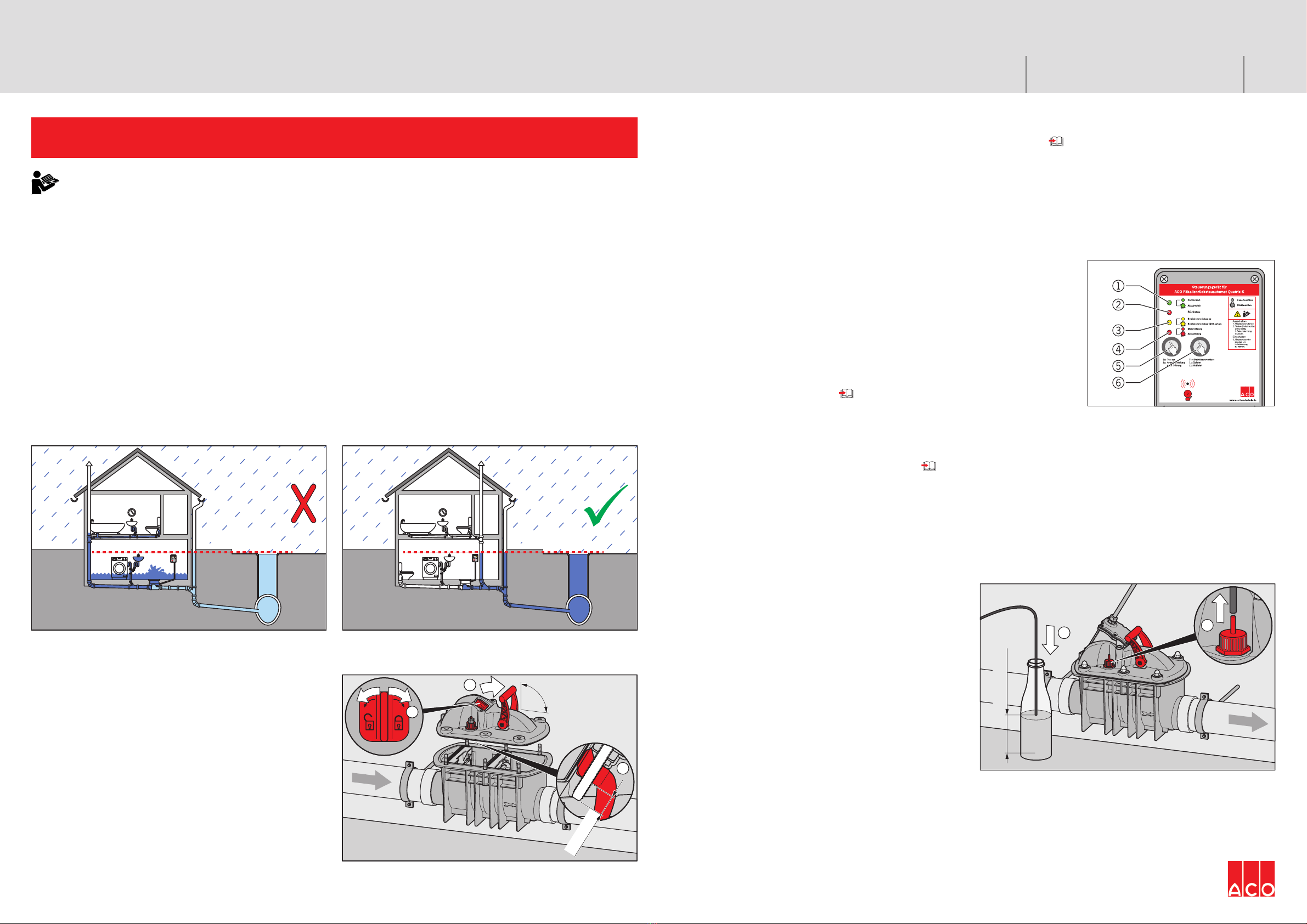
CAUTION Incorrect installation: Drainage points
ABOVE the backflow level must NOT be connected
upstream of the Quatrix unit as WC’s, baths and showers
cannot be used during a backflow situation.
Correct installation: Drainage points above the
backflow level MUST be connected downstream of
Quatrix unit. Sanitary units above the backflow level can
be used in g a backflow situation.
Netzbetrieb
1x:TonausTestBetriebsverschluss
1x:Zufahrt
2x:Auffahrt
2x:Grundeinstellung
nachStörung
Dauerleuchten
Ausschalten
1.Netzsteckerziehen
2.Tasten(links/rechts)
gleichzeitig
5Sekundenlang
drücken.
Einschalten
3.Netzsteckerein-
steckenum
Initialisierung
zustarten.
Blinkleuchten
Akkubetrieb
Rückstau
Betriebsverschlusszu
Motorstörung
Akkustörung
Betriebsverschlussfährtauf/zu
Mounting the Housing Cover
CAUTION When positioning the housing cover,
pay attention to the positions of the spindle and the
emergency lock.
ÎPlace the red manual drive nut (1) on the spindle and
turn it until the spindle is protruding approximately
20 mm from the threaded actuator (2).
ÎMove the red lever (emergency lock) to a vertical
position (3).
ÎPlace the housing cover on the housing and tighten
the cap nuts to between 5 and 8 Nm, alternating
between nuts on opposite sides.
ÎPush the red lever (emergency lock) as far as it will go
against the ow direction to open the emergency lock.
3.
90°
1.
2.
mm
Backflow level Backflow level
ACO Building Drainage
Prerequisites for Commissioning
■
Water tightness and function test of emergency lock have been performed; operating instructions.
■
Pressure hose is installed with a gradient (> 1%) and without any loops or kinks. This is very important otherwise the
pressure sensor will be unable to detect a backflow.
■
The control device is protected against flooding and frost (> 5°C), and is mounted in a way that makes it clearly visible
and easy to operate.
■
motor is mounted (spindle has been cleaned and greased before) and installed
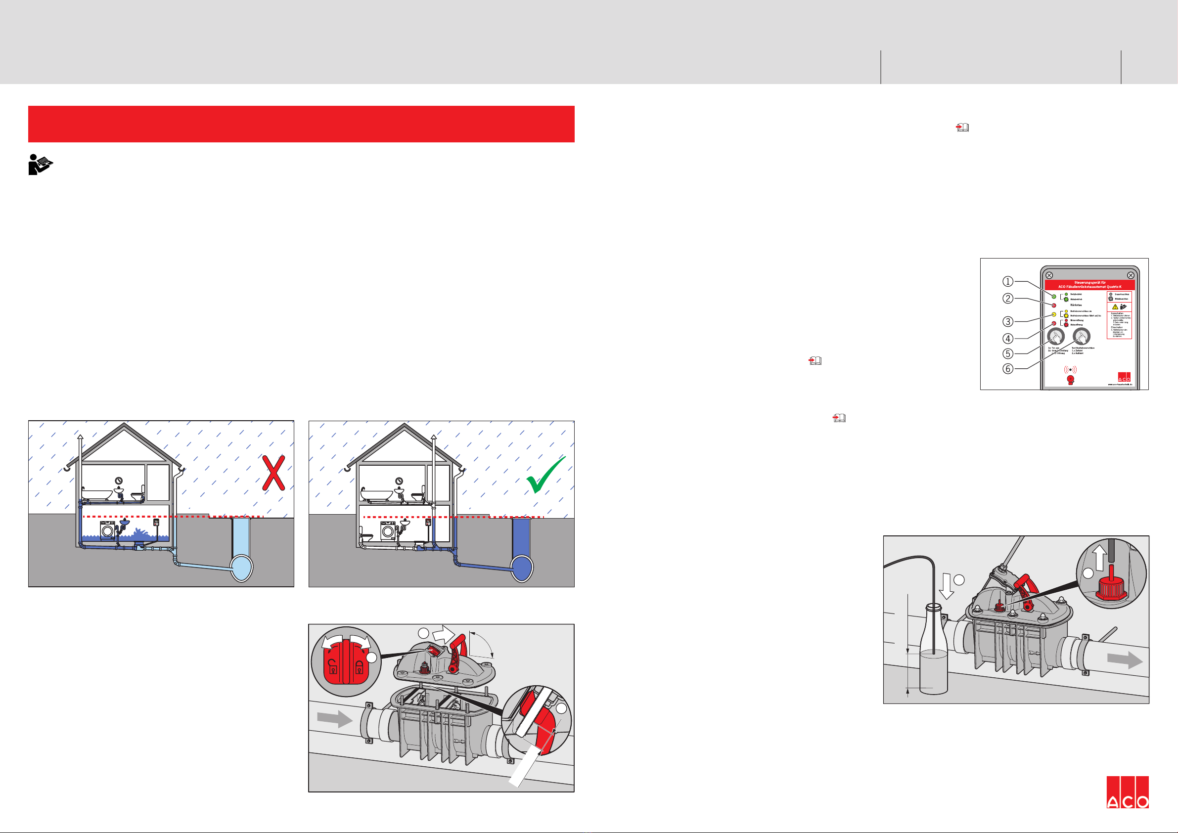
Switching On the Control Device
ÎConnect the mains plug to a mains socket with fuse protection. The control device will perform a self-test.
Self-test process:
■Green LED (1) lights up: control device is ready for operation (power supply
is established).
■Red LED (4) flashes (approx. 15 seconds): charge state of the battery (in
the control device) is being checked.
If the charge state is too low, the battery is charged (max. 10 minutes).
Red LED (4) flashes and alarm sounds: battery is deep-discharged or
defective, or the fuse is defective; operating instructions.
■Yellow LED (3) flashes: operating seal (backflow flap) is being checked. To
do this, the operating seal (backflow flap) is closed and reopened.
■Only green LED (1) lights up: automatic backflow stop is ready for operation.
■If this is not the case or if the alarm sounds, operating instructions.
Closing and opening the operating seal (backflow flap) mannually:
Î
To close: press key (6). The alarm sounds (can only be deactivated with key (5) in the event of a backflow or
malfunction).
ÎTo open: press key (6) again.
Checking Backflow Detection
ÎRemove the pressure hose from the pressure hose
connection (housing cover; 1).
ÎInsert the pressure hose approx. 150 mm into a
container filled with water, such as a bottle (2).
Correct backflow detection:
■Red LED (2) lights up.
■
Yellow LED (3) flashes while the operating seal closes.
■Green LED (3) lights up and alarm sounds: the
operating seal is closed.
ÎPress key (5) to deactivate the alarm signal.
ÎRemove the pressure hose from the container. The
operating seal opens automatically after approx. 30
seconds.
2.
150
mm
1.
ÎAttach the pressure hose to the Quatrix unit connection again and tighten it using the union nut.
Switching Off the Control Device
ÎRemove out the mains plug.
ÎPress keys (5) and (6) simultaneously for approx. 3 seconds.
All the LEDs will light up once as confirmation.
0850.01.02 V 1.0Issued: 2014–06–05