Acorn IS-D105 User manual

INSTRUCTION MANUAL
IS-D105
Intrinsically Safe Sounder
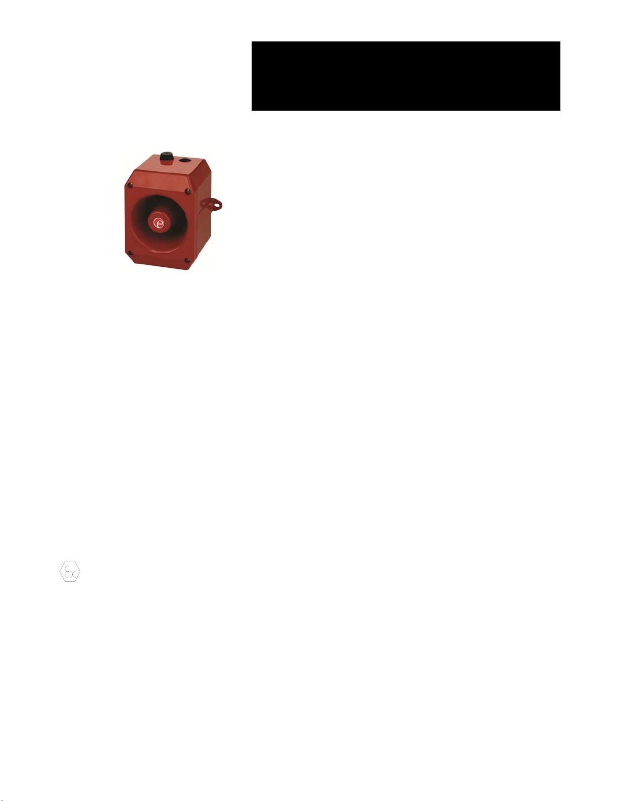
The IS-D105 is an ATEX and IECEx certified intrinsically safe
sounder which produces a loud warning signal in a
hazardous area. Forty-nine first stage alarm sounds can be
selected by internal switches and each one can be externally
changed to a second or third stage alarm sound. The
sounder may be used in all gas groups IIA, IIB and IIC. An IS-
DL105 intrinsically safe combined sounder and beacon is
also available.
2) Ratings and Markings
2.1 ATEX/IECEx certification
The IS-D105 sounder complies with the following standards:-
EN60079-0:2012 / IEC60079-0:2011
EN60079-11:2012 / IEC60079-11:2011
IEC 60079-26:2014
The EC-Type Examination Certificate SIRA 04ATEX2301X
has been issued by the Notified Body Sira. This confirms
compliance with the European ATEX Directive 94/9/EC for
Group II, Category 1 G equipment. The sounder carries the
Community Mark and subject to local codes of practice, may
be installed in any of the EEA member countries. The product
has also been approved to the IECEx scheme, Certificate no.
IECEx SIR04.0038X. This instruction sheet describes
installations which conform to EN60079-14:2008/IEC60079-
14:2007 Electrical Installation in Hazardous Areas. When
designing systems for installation outside the UK, the local
Code of Practice should be consulted.
The certification marking is as follows:
1) The certificate number has an ‘X’ suffix, which
indicates that the certificate contains one or more
special conditions for safe use. Those installing or
inspecting the equipment should refer to this section
of the certificate.
2) The equipment has not been assessed as a safety-
related device (as referred to by Directive 94/9/EC
Annex II, clause 1.5).
3) Installation of this equipment shall be carried out by
suitably-trained personnel in accordance with the
applicable code of practice.
4) Repair of this equipment shall only be carried out by
the manufacturer or in accordance with the
applicable code of practice.
5) The certification of this equipment relies on the
following materials used in its construction:
Enclosure: Aluminium Pressure Die Cast Body LM6
Sealing of Enclosure & Mechanism: ‘O’ Ring
If the equipment is likely to come into contact with
aggressive substances, then it is the responsibility of
the user to take suitable precautions that prevent it
from being adversely affected, thus ensuring that the
type of protection is not compromised.
“Aggressive substances” - e.g. acidic liquids or
gases that may attack metals, or solvents that may
affect polymeric materials.
“Suitable precautions” - e.g. regular checks as part
of routine inspections or establishing from the
material’s data sheet that it is resistant to specific
chemicals.
2.2 Zones, Gas Groups and Temperature Classification
The IS-D105 sounder has been certified Ex ia IIC T4 Ga.
When connected to an approved system it may be installed
in:
Zone 0 explosive gas air mixture
continuously present.
Zone 1 explosive gas air mixture likely to occur in
normal operation.
Zone 2 explosive gas air mixture not likely to occur,
and if it does, it will only exist for a short time.
Be used with gases in groups:
Group IIA propane
Group IIB ethylene
Group IIC hydrogen
Having a temperature classification of:
T1 450ºC
T2 300ºC
T3 200ºC
T4 135ºC
The IS-D105 sounder is CE marked for
compliance with the European
Explosive Atmospheres Directive
94/9/EC and the European EMC
Directive 89/336/EEC
II 1G Ex ia IIC T4 Ga (-40ºC <= Ta <= +60ºC)
www.acornfiresecurity.com

3) Installation requirements
SPECIAL CONDITIONS FOR SAFE USE (as stated on the
EC Type Examination Certificate SIRA 04ATEX2301X)
The equipment shall only be supplied via Terminals + w.r.t.
Terminals – from a barrier having a maximum open circuit
voltage Uothat is 28 V and a maximum short circuit current
Iothat is 93 mA, where Iois resistively limited. The barrier
shall be ATEX certified by a notified body.
The total capacitance connected to terminals + wrt – (i.e. the
capacitance of the cable plus any other capacitance) shall
not exceed 83 nF.
The equipment has an ingress protection rating of IP66;
however, if it has been supplied without a cable entry device,
then the user shall ensure that the device that is fitted will
provide an ingress protection that is appropriate to the
environment in which it is installed i.e. IP20 or better.
The enclosure may be manufactured from cast aluminium. In
rare cases, ignition sources due to impact and friction sparks
could occur. This shall be considered during installation,
particularly if the equipment is installed in an area requiring
Equipment Protection Level Ga.
3.1 Terminals + and –
Power is supplied to the sounder via the + and – terminals
which have the following input safety parameters:
The IS-D105 sounder may be powered from an ATEX
certified Zener barrier or galvanic isolator which have output
parameters equal to or less than 28V, 93mA and 660mW
where Io is resistively limited. The cable parameters stated
on the selected Zener barrier or galvanic isolator certificate
must be observed.
Up to three IS-D105 sounders can be connected in parallel
and powered from a common barrier or isolator. Connecting
two sounders in parallel will reduce the output from each by
about 3dB. Three sounders should only be powered from a
common supply when the maximum supply voltage is
available.
3.2 Terminals S2 and S3
When terminals S2 or S3 are connected to 0V (- terminal) the
sounder output tone changes to the second or third stage
alarm respectively. The input safety parameters for these
terminals are:
Ui = 28V
Ii = 0mA
Because the permitted input current is zero, these terminals
may only be connected to a diode return barrier, an
intrinsically safe relay or a galvanic isolator, all of which must
have been certified by an EC Notified Body. Only diode
return barriers with a voltage drop of less than 0.9V may be
used. Alternatively, these terminals may be connected
directly to a mechanically activated switch within the
hazardous area.
Fig 1 Simplified block diagram
3.3 Description
Fig 1 shows a simplified block diagram of an IS-D105
sounder. The device operates immediately when power is
applied to the + and – terminals which are duplicated to allow
a second sounder to be connected in parallel, or for an end of
line monitoring resistor to be installed. The output tone is
defined by the positions of the six internal switches and this
tone can be changed to a second or third stage alarm tone by
connecting terminals S2 or S3 to 0V. The tone generator is
crystal controlled to ensure that when two sounders are
started at the same time the output tones remain
synchronised.
3.4 Supply Voltage
The IS-D105 sounder has been designed to operate in a
hazardous area from a 24V dc supply via 28V 93mA resistive
ATEX and IECEx certified Zener Barriers or Galvanic
Isolators. The sounders may be tested or used in safe areas
without a Zener barrier or galvanic isolator, but at supply
voltages above 16V the internal current limit will function and
therefore it is recommended that they are not operated
continuously with a direct supply greater than 16V.
Fig 2 Location of field terminals and controls.
Ui 28V
Ii 93mA
Pi 660mW
Ci 0mA
Li 0mA
In
p
ut Terminals Volume Control Tone Setting
Switches 1-6
Sounder
Tone
DIP Switch
www.acornfiresecurity.com

4) Installation
Fig 3 Fixing hole locations
IS-D105 sounders should only be installed by trained
competent personnel.
4.1 Mounting
The IS-D105 sounder may be secured to any flat surface
using the two M6, 147.0mm pitch fixing centres. The
enclosure provides IP66 protection and is suitable for
installation in exterior locations providing it is positioned so
that water cannot collect in the horn, and the cable entry is
sealed.
4.2 Installation procedure
a. Secure the IS-D105 sounder to a flat surface via the
two M6, 147.0mm pitch fixing centres in the mounting
feet.
b. Remove the front of the sounder by unscrewing the
four captive screws and pulling the front away from
the enclosure.
c. Remove the PVC grommet and fit a 20mm cable
gland or conduit entry into the hole in the enclosure
and connect the field wiring to the appropriate sounder
terminals as shown in section 6 and fig 2 of this
manual. The power supply terminals + and - are
duplicated so that sounders may be connected in
parallel, or an end of line monitoring resistor may be
fitted.
d. Select the required output tone by positioning the 6-
way DIP switch as shown in Table 1.0 and Fig 2.
e. Apply power to the sounder and adjust the internal
volume control to provide the required sound level.
f. Replace the front of the sounder and tighten the four
captive cover screws.
5) Electrical System Design For Installation In
Hazardous Areas Using Zener Barriers
5.1 Single stage alarm
If the control switch is in the positive supply, or the power
supply is being turned on and off, only a single channel Zener
barrier is required as shown in Fig 3. This circuit may also be
used if the sounder is being controlled by a mechanically
activated switch on the hazardous area side of the barrier.
Fig 4 Single stage alarm using single channel barrier.
If the control switch must be in the negative supply, the circuit
shown in Fig 4 may be used. Any diode return barrier certified
Ex ia by a EC Notified Body may be used, providing its
voltage drop is less than 0.9V.
Fig 5 Single stage alarm using two channel barrier.
5.2 Multi-stage alarm
Connecting terminal S2 to 0V activates the second stage
alarm, and similarly terminal S3 for the third stage alarm. Fig
5 shows how the diode return barriers may be used. If only
two stages of alarm are required the third stage barrier
should be omitted, the 28V 93mA barrier and the single diode
return channel may then be contained in one package.
Fig 6 Multi stage alarm using Zener barriers.
Barrier
Power
Supply
28V 93mA
Positive
Safe AreaHazardous Area
IS-D105 Sounder
Terminals
On/Off
*
0V
+
To a
maximum
of 2 other
sounders
Barrier
Power
Supply
28V 93mA
Positive
Safe AreaHazardous Area
IS-D105 Sounder
Terminals
On/Off
*
0V
+
Barrier
Power
Supply
28V 93mA
Positive
Safe Area
Hazardous Area
IS-D105 Sounder
Terminals
On/Off
*
Diode Return
Barrier
Diode Return
Barrier
Diode Return
Barrier 3rd Stage*
2nd Stage*
+
0V
To a
maximum
of 2 other
sounders
To a
maximum
of 2 other
sounders
Detail of Fixing
Points
www.acornfiresecurity.com

6) Electrical System Design For Installation In
Hazardous Areas Using Galvanic Isolators
Galvanic isolators although more expensive than Zener
barriers, do not require a high integrity earth connection. For
small systems where a high integrity earth is not already
available, the use of galvanic isolators often reduces the
overall installation cost and simplifies design.
6.1 Single stage alarm
The IS-D105 sounder may be powered by any galvanic
isolator having output parameters within the limits specified in
section 4.3, which has been certified Ex ia by an EC Notified
Body. The sounder may be controlled by turning the galvanic
isolator on and off, or by a mechanically activated switch on
the hazardous area side of the isolator.
Fig 7 Single stage alarm using galvanic isolator.
6.2 Multi stage alarm
The IS-D105 sounder second and third stages may be
activated by using Galvanically Isolated Relays that have
output parameters within the limits specified in section 4.4.
which have been certified Ex ia by an EC Notified Body.
Fig 8 Multi stage alarm using galvanic isolated relays
7) Cable Parameters
The maximum permitted cable parameters are as specified
on the certificate of the Zener barrier or galvanic isolator that
has been selected for the installation. Normally the limits are
not restrictive, but care should be taken not to exceed a
capacitive limit of 83nF for installations when very long cables
are used.
8) Volume Control
The output level of the IS-D105 sounder can be set by
adjusting the volume control potentiometer (see Fig 2).
Safe Area
Hazardous Area
+
-
IS-D105 Sounder
Terminals
Galvanic Isolator
Power
Power
-
+
Safe Area
Hazardous Area
Galvanic Isolator
IS-D105 Sounder
Terminals
Galvanic Isolated Relay
-
On/Off*
On/Off*
To a
maximum
of 2 other
sounders
www.acornfiresecurity.com

Tone
Number
Tone Description
Switch
Settings
1 2 3 4 5 6
Second
Stage
Alarm
Third
Stage
alarm
Tone 1
Tone 2
Tone 3
Tone 4
Tone 5
Tone 6
Tone 7
Tone 8
Tone 9
Tone 10
Tone 11
Tone 12
Tone 13
Tone 14
Tone 15
Tone 16
Tone 17
Tone 18
Tone 19
Tone 20
Tone 21
Tone 22
Tone 23
Tone 24
Tone 25
Tone 26
Tone 27
Tone 28
Tone 29
Tone 30
Tone 31
Tone 32
Tone 33
Tone 34
Tone 35
Tone 36
Tone 37
Tone 38
Tone 39
Tone 40
Tone 41
Tone 42
Tone 43
Tone 44
Tone 45
Tone 46
Tone 47
Tone 48
Tone 49
Continuous 340Hz
Alternating 800/1000Hz @ 0.25s intervals
Slow whoop 500/1200Hz @ 0.3Hz with 0.5s gap repeated
Sweeping 500/1000Hz @ 1Hz
Continuous 2400Hz
Sweeping 2400/2900Hz @ 7Hz
Sweeping 2400/2900Hz @ 1Hz
Siren 500/1200/500Hz @ 0.3Hz
Sawtooth 1200/500Hz @ 1Hz - D.I.N.
Alternating 2400/2900Hz @ 2Hz
Intermittent 1000Hz @ 1Hz
Alternating 800/1000Hz @ 0.875Hz
Intermittent 2400Hz @ 1Hz
Intermittent 800Hz 0.25s ON, 1s OFF
Continuous 800Hz
Intermittent 660Hz 150Ns ON, 150ms OFF
Alternating 544Hz (100ms) / 440Hz (400ms) – NFS 32-001
Intermittent 660Hz 1.8s ON, 1.8s OFF
Sweep 1400Hz to1600Hz up 1s 1600Hz to 1400Hz down 0.5s
Continuous 660Hz
Alternating 554/440Hz @ 1Hz
Intermittent 544Hz @ 0.875Hz
Intermittent 800Hz @ 2Hz
Sweeping 800/1000Hz @ 50Hz
Sweeping 2400/2900Hz @ 50Hz
Simulated bell
Continuous 554Hz
Continuous 440Hz
Sweeping 800/1000Hz @ 7Hz
Continuous 300Hz
Sweeping 660/1200 @ 1Hz
Two Tone Chime
Intermittent 745Hz
Alternating 1000/2000Hz @ 0.5s – Singapore
420Hz @ 0.625s - Australian Alert
500-1200Hz 3.75s / 0.25s - Australian Evacuate
Continuous 1000Hz
Continuous 2000Hz
Intermittent 800Hz 0.25s ON 1s OFF
Alternating 544Hz (100ms) / 440Hz (400ms) – NFS 32-001
Motor Siren – Slow rise to 1200Hz
Motor Siren – Slow rise to 800Hz
Continuous 1200Hz
Motor Siren – Slow rise to 2400Hz
Intermittent 1000Hz 1s ON, 1s OFF
Sawtooth 1200/500Hz @ 1Hz - D.I.N. (PFEER P.T.A.P)
Intermittent 1000Hz 1s ON, 1s OFF – PFEER General Alarm
420Hz @ 0.625s - Australian Alert
500-1200Hz 3.75s / 0.25s - Australian Evacuate
0 0 0 0 0 0
1 0 0 0 0 0
0 1 0 0 0 0
1 1 0 0 0 0
0 0 1 0 0 0
1 0 1 0 0 0
0 1 1 0 0 0
1 1 1 0 0 0
0 0 0 1 0 0
1 0 0 1 0 0
0 1 0 1 0 0
1 1 0 1 0 0
0 0 1 1 0 0
1 0 1 1 0 0
0 1 1 1 0 0
1 1 1 1 0 0
0 0 0 0 1 0
1 0 0 0 1 0
0 1 0 0 1 0
1 1 0 0 1 0
0 0 1 0 1 0
1 0 1 0 1 0
0 1 1 0 1 0
1 1 1 0 1 0
0 0 0 1 1 0
1 0 0 1 1 0
0 1 0 1 1 0
1 1 0 1 1 0
0 0 1 1 1 0
1 0 1 1 1 0
0 1 1 1 1 0
1 1 1 1 1 0
0 0 0 0 0 1
1 0 0 0 0 1
0 1 0 0 0 1
1 1 0 0 0 1
0 0 1 0 0 1
1 0 1 0 0 1
0 1 1 0 0 1
1 1 1 0 0 1
0 0 0 1 0 1
1 0 0 1 0 1
0 1 0 1 0 1
1 1 0 1 0 1
0 0 1 1 0 1
1 0 1 1 0 1
0 1 1 1 0 1
1 1 1 1 0 1
0 0 0 0 1 1
Tone 2
Tone 17
Tone 2
Tone 6
Tone 3
Tone 7
Tone 10
Tone 2
Tone 15
Tone 7
Tone 2
Tone 4
Tone 15
Tone 4
Tone 2
Tone 18
Tone 2
Tone 2
Tone 2
Tone 2
Tone 2
Tone 2
Tone 6
Tone 29
Tone 29
Tone 2
Tone 26
Tone 2
Tone 7
Tone 2
Tone 26
Tone 26
Tone 2
Tone 38
Tone 36
Tone 35
Tone 9
Tone 34
Tone 23
Tone 31
Tone 2
Tone 2
Tone 2
Tone 2
Tone 38
Tone 47
Tone 46
Tone 49
Tone 26
Tone 5
Tone 5
Tone 5
Tone 5
Tone 20
Tone 5
Tone 5
Tone 5
Tone 2
Tone 5
Tone 5
Tone 5
Tone 5
Tone 5
Tone 5
Tone 5
Tone 27
Tone 5
Tone 5
Tone 5
Tone 5
Tone 5
Tone 5
Tone 5
Tone 5
Tone 15
Tone 5
Tone 5
Tone 5
Tone 5
Tone 5
Tone 15
Tone 5
Tone 45
Tone 5
Tone 5
Tone 45
Tone 45
Tone 17
Tone 27
Tone 5
Tone 5
Tone 5
Tone 5
Tone 34
Tone 37
Tone 37
Tone 5
Tone 37
Tone Selection – To select the required first stage tone set the tone switches 1 to 6 (see
Fig 2) to the tone setting shown in the table below. The table also shows which 2nd and 3rd
stage tones are available for use with the selected first stage tone if more than one tone
output stage is required.
www.acornfiresecurity.com
This manual suits for next models
2
Table of contents