Acorp 56000BPS User manual

High Performance
V.90/K56flex/V.34+/V.42bis
56000BPS
Plug & Play Internal
Data/Fax/Modem
User's Manual
Contents
SectionOne-Introduction........................... 1
SectionTwo-InstallationGuide .................. 1
SectionThree-ATCommandSet ............... 5
Section Four - S Registers........................10
AppendixASpecifications ........................ 10
Appendix B Installations ..........................11
F-1156IV/R9

The information contained in this manual has been
validated at the time of this manual's production.
The manufacturer reserves the right to make any
changes and improvements in the product de-
scribed in this manual at any time and without
notice. Consequently the manufacturer assumes
no liability for damages incurred directly or indi-
rectly from errors, omissions or discrepancies be-
tween the product and the manual.
All registered trademarks are the property of their
respective owners.
Copyright©1997Allrightsreserved.Noreproduction
ofthisdocumentinanyformispermittedwithoutprior
writtenauthorizationfromtheManufacturer.

1
1.TurnoffpowertoWindows98PC,removePCcover,
insertcardtoanavailablePCIslot,closecover,turnon
power.
2.When Windows 98 loads,it will detect the new hard-
wareand askfor adriver. thefollowingwindowshould
appear.
3.ClickNextandyoushouldsee:
Section One - Introduction
This 56 kbps* Plug and Play FAX/Data Modem
connectsyour computer toallpopular highspeedmo-
demsavailabletoday.Itsincorporates"V.90/K56Flex"
(56Kbps)
technology to provide increased download
speedsusingregulartelephonelines.Themodemincor-
poratesPlugandPlayforeaseofinstallation.
Thismanualdescribesthe ATcommandsandS-
registers so that your system can be customized for a
particularoperatingenvironment.
*Note: K56flex is capable of downloading at 56kbps.
However, current FCC regulations limit its speeds to
53Kbps.
Section Two - Installation Guide
2
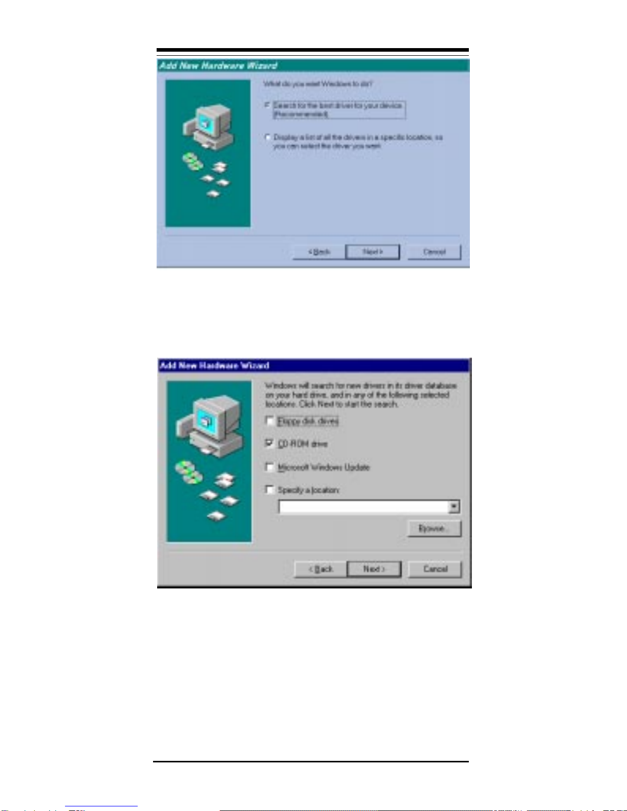
4.Select "Search for the best driver for your device"
Option.ClickNextandyoushouldsee:
5.InserttheCD-ROMthatcomeswithyourModemintothe
CD-ROM drive.MakesuretheCD-ROMdrivecheckbox
ischecked.Leaveallothercheckboxesblank.ClickNext
andyoushouldsee:

3
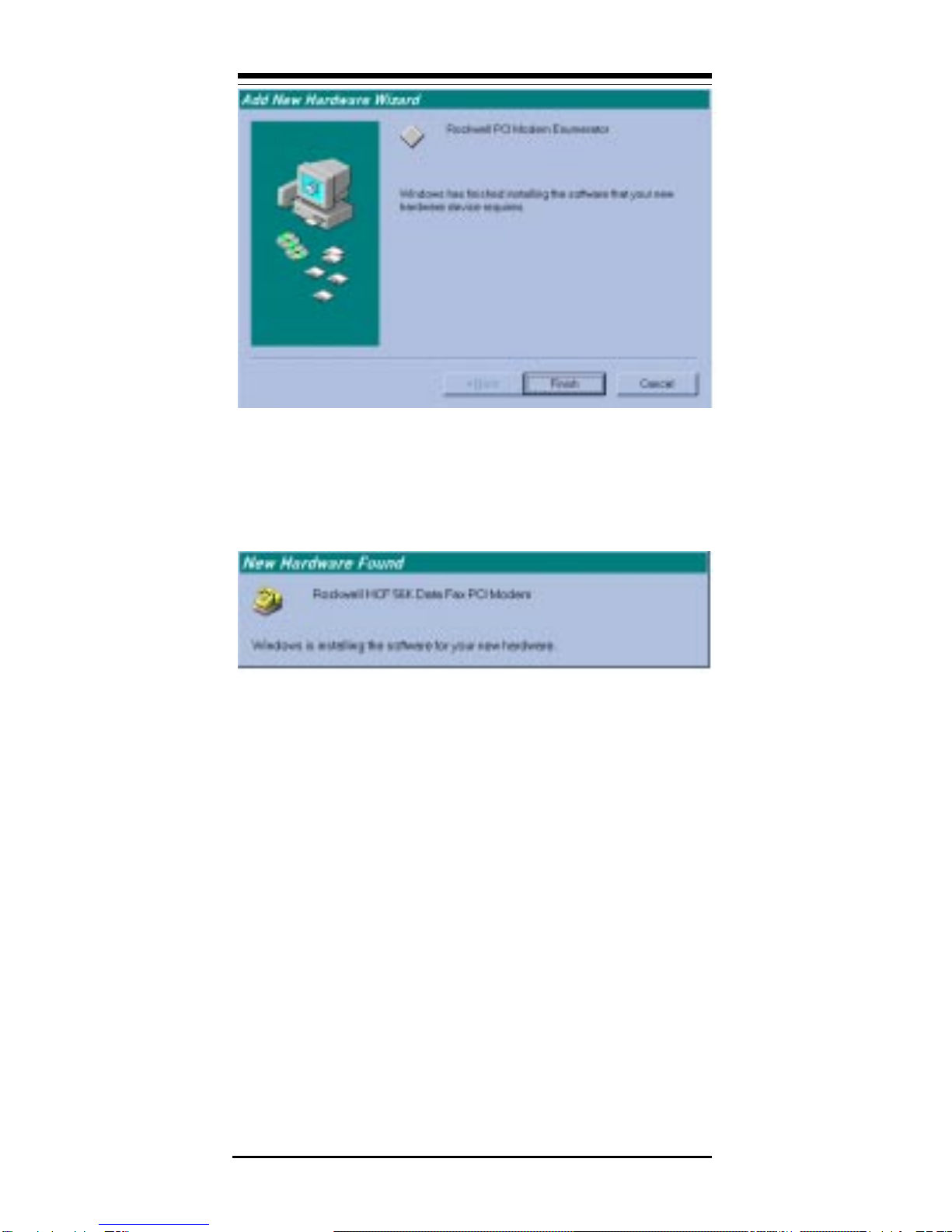
6.ClickNextandyoushouldseethefollowing.
7.WaituntilWindows98finishescopyingalltherequired
files.
4
8.When you see the above window, Windows 98 has
alreadyfinishedcopyingallthefiles.ClickFinishandyou
should see the following window.
9.YourModemisnowinstalledinWindows98.

5
Section Three - AT Command Set
3.1 Commands
Commandsareacceptedbythemodemwhileitis
inCommandMode.YourmodemisautomaticallyinCom-
mand Mode until you dial a number and establish a
connection.Commandsmaybesenttoyourmodemfrom
a PC running communication software or any other
terminaldevices.
Yourmodemiscapableofdatacommunicationat
rates of: 300, 1200, 2400, 4800, 9600, 14400, 19200,
28800,38400,57600,and115200bps.Makesureyour
COMportbaudrate in yourcommunicationssoftwareis
set to one of the above speeds.
3.2 Command Structure
Allcommandssenttothemodemmustbeginwith
ATandendwithENTER. Allcommandsmaybetyped
ineitherupperorlowercase,butnotmixed.Tomakethe
commandlinemorereadable,spacesmaybeinserted
between commands. If you omit a parameter from a
command that requires one, it is just like specifying a
parameterof0.Example:
ATH[ENTER]
Thiscommandcausesyourmodemtohangup.
3.3 BasicAT Commands
In the following listings, all default settings are
printedinbold text.
Command Function
AManually answer incoming call.
A/ Repeat last command executed. Do not
precede A/ with AT or follow with
ENTER.
D_ 0 - 9, A-D, # and *
L last number redial
P pulse dialing
T touch-tone dialing
W wait for second dial tone
, pause
@ wait for five seconds of silence

6
! flash
; return to Command Mode after dialing
E_ E0 Commands are not echoed
E1 Commands are echoed
+++ Escape Characters Switch from Data
ModetoCommandMode
H_ H0 Force modem on-hook (hang up)
H1 Force modem off-hook (make busy)
I_ I0 Reports product code
I1 Reports Pre-Computed checksum
I2 Internal memory test
I3 Firmware ID
I4 Reports data pump model and internal
code revision
L_ L0 Low speaker volume
L1 Low speaker volume
L2 Medium speaker volume
L3 High speaker volume
M_ M0 Internal speaker off
M1 Internal speaker on until carrier
detected
M2 Internal speaker always on
M3 Internalspeakeronuntilcarrierdetected
and off while dialing
O_ O0 Return to Data Mode
O1 Return to Data Mode and initiate an
equalizer retrain
PSet Pulse dial as default
Q_ Q0 Modem sends responses
Q1 Modem does not send responses
Sr? Read and display value in register r.
Sr=n Set register r to value n (n = 0-255).
T Set Tone Dial as default
V_ V0 Numeric responses
V1 Word responses
X_ X0 Hayes Smartmodem 300 compatible
responses/blind dialing.
X1 SameasX0plusallCONNECTresponses/
blinddialing
X2 Same as X1 plus dial tone detection
X3 Same as X1 plus busy detection/blind
dialing

7
X4 All responses and dial tone and
busy signal detection
Z_ Z0 Reset and retrieve active profile 0
3.4 ExtendedATCommands
&C_ &C0 Force Carrier Detect Signal High (ON)
&C1 Turn on CD when remote carrier is
present
&D_ &D0 Modem ignores the DTR signal
&D1 Modem returns to Command Mode after
DTRtoggle
&D2 Modem hangs up, returns to the
Command Mode after DTR toggle
&F_ &F Recall factory default configuration
&G_ &G0 Guard tone disabled
&G1 Guard tone disabled
&G2 1800 Hz guard tone
&P_ &P1 Select 33 ratio M/B at 10pps
&P3 Sameas&P1settingbutat20pulsesper
second
&V &V0 Displays Active and Stored Profiles
&W_ &W0 Stores the active profile as Profile 0
%E_ %E0 Disable auto-retrain
%E1 Enable auto-retrain
+MS? Displays the current Select Modulation
settings
+MS=? Displays a list of supported Select
Modulation options
+MS=a,b,c,d,e,f Select modulation. a,b,c,d,e,f
default=V.90,1,75,33600,
75,56000.Parameter¡§a¡¨specifiesthe
modulation protocol desired where:
B103=Bell103,B212=Bell212,
V21=V.21,V22=V.22,V22B=V.22bis,
V23C=V.23,V32=V.32,V32B=V.32bis,
V34=V.34,K56FLEX=K56FLEX,V.90=V.90.
Parameter¡§b¡¨specifies automode
operations where=automode disabled,
1=automomod enabled.Parameter
¡§c¡¨specifies the minimum connected
speed of the transmit direction.
Parameter¡§d¡¨specifiesthemaximum
connected speed of the transmit

8
direction. Parameter¡§e¡¨specifies the
minimumconnecteddirection.Parameter
¡§f¡¨specifies the maximum connected
direction.
3.5 MNP/V.42/V.42bisCommands
+ES? Displays the current Error Control
and Sychronous Mode Selection
settings.
+ES=? Displays a list of supported Error
control and Sychronous Mode
Selection options.
+ES=a,b,c Error Control and Sychronous Mode
Selectionwhere:a=1-4,b=0,2-4,c=1
,2,4,5,6. a,b,c default=3,0,2.
Parameter "a" specifies the initial
requested mode of operation where
1=Normal Mode, 2=V.42 without
Detection Phase, 3=V.42 with
DetectionPhase,4=MNP.Parameter
"b" specifies the acceptable fallback
mode of operation where:0=LAPM,
MNP, or Normal Mode error control
optional, 2=LAPM or MNP error
control required, 3=LAPM error
control required, 4=MNPerrorcontrol
required.Parameter"c"specifies the
acceptable fallback modeof operation
where:1=Normal Mode, 2=LAPM,
MNP,or Normal Mode error control
optional, 4=LAPM or MNP error
controlrequired,5=LAPMerrorcontrol
required, 6=MNP error control
required.
+ER? Displays the current Error control
reporting settings.
+ER=? Displays a list of supported Error
control reporting options.
+ER=n n=0 Error control reporting disabled.
n=1 Error control reporting enabled.
(Default.)
+DS? Displays the current Data
Compreesion settings.
Table of contents


