Acre Aperio AH40 User manual

Reshaping Security
acre Security Integration
Guide: Aperio®
AH40
Wireless

7KLV PDQXDO LV SURSULHWDU\ LQIRUPDWLRQ RI acre 8QDXWKRUL]HG UHSURGXFWLRQ RU GLVWULEXWLRQ
RIWKLV PDQXDOLV VWULFWO\ IRUELGGHQZLWKRXW WKHZULWWHQ FRQVHQWRI
acre7KHLQIRUPDWLRQFRQWDLQHGLQWKLVPDQXDOLVIRULQIRUPDWLRQDOSXUSRVHVRQO\DQGLVVXEMHFW
WR FKDQJH DW DQ\ WLPH ZLWKRXW QRWLFH acre DVVXPHV QR UHVSRQVLELOLW\ IRU
LQFRUUHFWRURXWGDWHGLQIRUPDWLRQWKDWPD\EHFRQWDLQHGLQWKLVSXEOLFDWLRQ
The controllers XVH equipment that generates, XVHV, and radiateVradio frequency energy
,I not installed and GHSOR\HG in accordance with thHJXLGHOLQHVRIWKLVLQVWDOODWLRQ
manual, WKH\ PD\ FDXVH Karmfulinterferencetoradiocommunications.Operationof this
equipment in aresidential area may cause harmful interference Ln which case the userwill
be required to correct the interference attheLURZQ expense.
The Mercury controllers and subcontrollersshall be installed in accordance with this
installation manual and in accordance with the National ElectricCode(N.E.C),ANSI and
NFPA 70 Regulations and recommendations.
PXEOLVKDate:May,2023
0DQXDO1XPEHUD-AH40 Integration v.1.4
©Copyright 2002-203acre All rights reserved.
Warranty
All acre products are warranted against defect in materials and workmanship for WZR yearV
from the date ofshipment. acre will repair or replace products that prove defective and are
returned to acre within the warranty period with shipping prepaid. The warranty of acre
products shall not apply to defects resulting from misuse, accident, alteration, neglect,
improper installation, unauthorized repair, or acts of God. acre shall have the right of final
determination as to the existence and cause of the defect. No other warranty, written or oral is
expressed or implied.
Phone: (972) 818-7001
Fax (972) 818-7003
www.helpdesk.acre-co.com

acre Software License Agreement
THE ENCLOSED SOFTWARE PACKAGE IS LICENSED BY acre. TO CUSTOMERS FOR THEIR NON-EXCLUSIVE
USE ON A COMPUTER SYSTEM PER THE TERMS SET FORTH BELOW.
DEFINITIONS: acre shall mean acre, which has the legal right to license the computer application known as DNA Fusion
herein known as the Software. Documentation shall mean allprinted material included with the Software. Licensee shall
mean the end user of this acre Software. This Software Package consists of copyrighted computer software and copyrighted
user reference manual(s).
LICENSE: acre, grants the licensee a limited, non-exclusive license (i) to load a copy of the Software into the memory of a
single (one) computer as necessary to use the Program, and (ii) to make one (1) backup or archival copy of the Software for
use with the same computer. The archival copy and original copy of the Software are subject to the restrictions in this
Agreement and both must be destroyed or returned to acre if your continued possession or use of the original copy ceases or
this Agreement isterminated.
RESTRICTIONS: Licensee may not sub license, rent, lease, sell, pledge or otherwise transfer ordistribute the original copy
or archival copy of the Software or the Documentation. Licensee agrees not to translate, modify, disassemble, decompile,
reverse engineer, or create derivative works based on the Software or any portion thereof. Licensee also may not copy the
Documentation. The license automatically terminates without notice if Licensee breaches any provision of this Agreement.
TRANSFER RIGHTS: Reseller agrees to provide this license and warranty agreement to the end user customer. By
installation of the software, the end user customer and reseller agree to be bound by the license agreement and warranty.
LIMITED WARRANTY: acre warrants that it has the sole right to license the Software to Licensee. Upon registration by the
Licensee, acre further warrants that the media on which the Software is furnished will be free from defects in materials and
workmanship under normal use for a period of twelve (12) months following the delivery of the Software to the Licensee.
ACRE NA’sentire liability and your exclusive remedy shall be the replacement of the Software if the media on which the
Software is furnished proves to be defective. EXCEPT AS PROVIDED IN THIS SECTION, THE IMPLIED
WARRANTIES OF MERCHANTABILITY AND FITNESS FOR A PARTICULAR PURPOSE ARE EXPRESSLY
DISCLAIMED. IN PARTICULAR, EXCEPT AS PROVIDED IN THIS SECTION, WITH RESPECT TO ANY
PARTICULAR APPLICATION, USE OR PURPOSE, LICENSOR DOES NOT WARRANT THAT THE PRODUCTS
WILL MEET THE LICENSEE’S REQUIREMENTS, THAT THE PRODUCTS WILL OPERATE IN THE
COMBINATIONS OF 3RD PARTY SOFTWARE WHICH THE LICENSEE MAY SELECT TO USE, OR THAT THE
OPERATION OF THE PRODUCTS WILL BE UNITERRUPTED OR ERROR FREE. NEITHER OPEN OPTIONS, NOR
ITS VENDORS SHALL BE LIABLE FOR ANY LOSS OF PROFITS, LOSS OF USE, INTERRUPTION OF BUSINESS,
NOR FOR INDIRECT, SPECIAL, INCIDENTAL, OR CONSEQUENTIAL DAMAGES OF ANY KIND WHETHER
UNDER THIS AGREEMENT OR OTHERWISE. IN NOCASE SHALL OPEN OPTIONS’ LIABILITY EXCEED THE
PURCHASE PRICE OFTHESOFTWARE.
The disclaimers and limitations set forth above will apply regardless of whether you accept the Software.
TERMINATION: acre may terminate this license at any time if licensee is in breach of any of its terms or conditions. Upon
termination, licensee will immediately destroy the Software or return all copies ofthe Software toacre, along with any
copies licensee has made.
APPLICABLE LAWS: This Agreement is governed bythe laws of the State of Texas, including patent and copyright laws.
This Agreement will govern any upgrades, ifany, to the program that the licensee receives andcontains theentire
understanding between the parties and supersedes any proposal or prior agreement regarding the subject matter hereof.
AH40 Gateway
In This Chapter
Integration Guide Page 1
D
Aperio® AH40 IP Communication Hub
The Aperio® AH40 is a IP Communications (Comm) Hub designed to work with the Aperio® devices and lock
sets. The lock sets and Devices include smart cylinder locks, integrated lock/door sensor combo’s, cabinet
and handle lock/reader combo’s. Please contact your local RSM for more information or the list of lock sets
and devices oered by acre Security
Aperio® Hub Integration
The Aperio® AH40 Ethernet Enabled Communication
Hub functions as a bridge between ASSA-ABLOY/
Aperio® enabled locks and a variety of acre Security
enabled access control systems such as DNA Fusion.
This allows users of systems such as DNA Fusion
operators to control the Aperio and ASSA-ABLOY
(ASSA) locks remotely from the software.
The Mercury LP 1501, 1502, 2500 and 4502
controllers with the latest Firmware Version or
1.30.1.0663 or higher will support the Aperio®
Hub integration. The controllers support Ethernet
communication to up to 32 Subcontrollers and 64
ACMS. The Aperio® Hub communicates directly with
Aperio®-enabled locks via an encrypted 2.46-Hz
wireless link on 16 distinct channels using AES-128
Bit Encryption. Each Aperio® Hub includes mounting
hardware and instruction manual.
When a cardholder presents a card to an ASSA/
Aperio® lock, the credential information is sent
wirelessly to the Aperio® Hub. The hub then routes
the information to the controller, which veries the
access rights. The resulting decision is communicated
back to the Aperio® Hub, which either grants or
denies access.
The integration process includes two (2) steps:
●Hardware Setup - Wire the Aperio® Hub using CAT-5e Ethernet Connection and power from either
POE+ enabled switch devices or from a standalone power source.
●DNA Fusion Integration - After the hardware is connected, add the Aperio® Hub to DNA Fusion
and build doors in sequence from the readers, inputs, and outputs associated with the Aperio®
Hub.
√ AH40 Gateway Characteristics and General Information
√ Initial Conguration of the AH40 Gateway
√ Connecting and Conguring the Gateway and Lock sets in DNA Fusion

Integration Guide Page 2
Aperio Integration
Aperio® Hardware Setup
Connecting the AH40 Hub to the Local Area Network (LAN)
The AH40 communicates to the Mercury enabled Controller via a Networked Ethernet Connection. At a
Minimum, the use of a CAT-5e connector complying with 10BASE-T / 100BASE-TX standard must be used.
The connection can be achieved by connecting the Ethernet cable to the J700 connector located on the
back of the device as pictured below.
The device can be powered through the use of the J800 port connector to an extrernal power source or by
using a POE+ Enabled Switch. The Connection must be an IEEE 802.3.af compliant Power Sourcing Device.
Recommended power source is 1.2w and less than 3 amps. If the possibility of surges over 3 amps exists
then a over current protection device must be used.
Continued on the following page

Integration Guide Page 3
Aperio Integration
AH40 Jumpers
The AH40 has two jumpers on the back of the device. The jumpers can only be accessed by removing the
device from its wall mount. The Jumpers and description are as follows:
Jumpers Description
J400 ANTENNA Select external antenna by connecting the
two right pins.
Select internal antenna by connecting the
two left pins.
J200 PAIR Select pairing mode by connecting the two
right pins.
If the pairing jumper if removed within 10 seconds from from boot up and the Hub LED is
lit, all paired devices will be unpaired.
i

Integration Guide Page 4
Aperio Integration
AH40 External Antenna
The AH40 has the ability to transmit information and form a wireless external connection with all locks
using a 2.5 gHz connection along the 2400 – 2483,5 MHz frequency range using 16 individual channels.
This connection is protected using an AES 128 bit encryption for every connection. The Wireless
Transmission power is along 10 dBm/MHz and the peak value has been measured in accordance with EN
ETSI 300 328 Maximum spectral density.
The AH40 comes out of the box with the ability to connect using a forward propagating antenna located
inside the unit. It also has the ability to connect to an external antenna using the following steps.
1. Power O the AH40 Unit by Disconnecting the Ethernet Cable if powered using the POE method or
Power Connector if using an external power source.
2. Locate the External Antenna Plug on the Upper-Right hand side of the unit. Gently Pry the cover from
the unit using your nger nail or a at head screw driver.
3. Connect the external antenna
to the connector. The antenna is
an Dipole antenna with a slight
dead zone for signal propagation
located on the top and bottom of
the external antenna post. The
antenna should be angled to be
perpendicular to the wireless device
locations it will be communicating
with.
Once you have connected the
external antenna. You will need
to Change the J400 Jumper to
Connect the Right-Two jumper pins
when facing the unit from the back.
You have now congured the unit to
be used with an external Antenna.
You may now reconnect the unit to
power and remount the unit to its
back plate as shown in the AH40
User manual From ASSA/Aperio®.
Care should be taken when prying o cover so that the connectors located under
the cover
!
Continued on the following page

Integration Guide Page 5
Aperio Integration
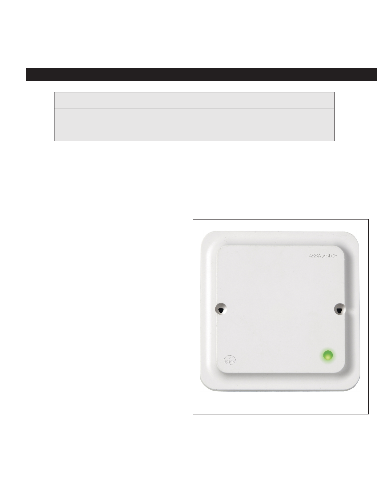
AH40 Status Lights
The AH40 comes with a two LED Status lights. The external status light is congured to
provide status information pertaining to the operational status of the unit. The Status light
scheme includes the details shown below.
The second LED is located in the back of the unit and allows for
an instant verication and assessment of the network connection
status. For additional information pertaining to the Network
Status LED please contact ASSA/Aperio® customer service.
Conguring the AH40 with Aperio® USB (Dongle)
Conguring the AH40
In order to properly congure the AH40 and connect it to your access control system, you are required
to use the Aperio® USB or otherwise referred to as the USB radio dongle as well as the Aperio®
Programming Application. The program application can be found at the following link:
https://assaabloyresources.com.au/downloads/Aperio-software/setup-progapp-28.0.43-4cd7502.exe
For more information regarding the installation of the Aperio® Program Application please
visit their website at assaabloyresources.com or contact their customer support.
i

Integration Guide Page 6
Aperio Integration
Once the software is installed you will then be able to Plug-In the Aperio® USB adn follow these directions
to initially connect to the system.
1. Connect and Power Up the AH40 hub. Once you have connected it and it has nished its power up
sequence you may Connect the Aperio® USB Dongle.
2. Open the Aperio® Program Application (App) and Select Quick Scan. Your AH40 hub should be
detected and listed in the program as shown below:
Click on Show Details
3. Right-Click on the Hub Row and Select Communication Hub>Congure.
Integration Guide Page 7
Aperio Integration
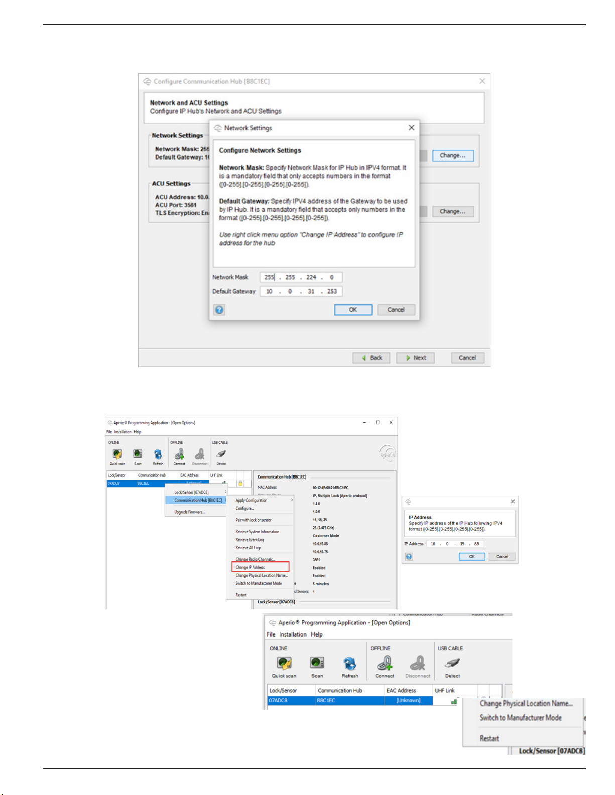
You will now be able to Modify the AH40’s Network Settings such as the Network Mask and Gateway to
Match the existing (W)LAN Conguration. Click OK.
4. Right-Click on the AH40 Row and Select Change IP Address. Add the required IP Address provided by
IT or the customer.
5. Right-Click on the AH40 Row and Make
sure that it is in Manufacturer mode by
Selecting Switch to Manufacturer Mode.
Next We will congure the address of the
controller.

Integration Guide Page 8
Aperio Integration
6. Right-Click on the Hub Row and
Select Communication Hub>Congure if
the window is not already open and Click
on the ACU Settings Change Button.
The ACU Settings Window will open.
Type In the ACU or Controller IP Address
as well as Verify that the ACU Port is 3561
and Check the Enable TLS box.
7. Click OK.
We will now continue the installation
by adding the Aperio® AH40 Hub as a
Subcontroller in DNA Fusion
Adding the AH40 Hub to DNA Fusion
Once the initial hardware conguration has been completed, you will now need to add it to your access
control system. For the purpose of this guide, we will be using DNA Fusion. To start, you will need to Log
In to DNA Fusion using your Username and Password. Once in you will need to Open your Hardware tree
and Locate the Controller that was used for the ACU Address in Step 6 on this page.
1. Right-Click on the Controller who’s address was used in the ACU Step. Select Add>Add
Subcontroller... A new window will appear.
2. Type In the Description for the AH40 in its respective line (Name of the AH40 location or reference
name). Click on the Drop Down under Type/Preview and Select the Aperio® IP Hub. Type in the IP
Address used for the Hub in the IP Addr: line. Click OK.

Integration Guide Page 9
Aperio Integration
3. Verify that the AH40 Comes Online and then Double-Click the Controller connected to the AH40 to
open the Controller Conguration window.
4. Click on Stored Quantities and then Click on the Use TLS for Aperio IP Check Box.
5. Return to the Aperio® Program App and Right-Click on the AH40 just added to DNA and Select
Communication Hub>Switch to Customer Mode. A New Window will appear.

Integration Guide Page 10
Aperio Integration
6. Click on Change and then Click on Switch to Customer mode in device. Click OK. This will enable
the use of the TLS encryption for communication with the LP series Mercury Controller (Series 3/Red
Controller).
In some instances, you may need to Right-Click on the Controller and Select Controller
Commands>Reset prior to the controller and the AH40 both being registered as online after nishing the
initial conguration. Please contact customer support if there are any issues in bringing the Controller and
AH40 online.
Next we will go over how to add locks or sensors to the AH40 and then pull the linked Locks and/or
Sensors into DNA Fusion.
The TLS settings will be restricted to TLS 1.1 and 1.2. Please talk to your
network administrator to ensure that these settings will work with your current
network security plan.
!
Integration Guide Page 11
Aperio Integration
Adding Locks to the Aperio® USB Application
Prior to any locks and wireless devices being pulled into DNA Fusion, they will rst need to be added and
congured by using the App with the AH40 hub. To do this, you will need to make sure the Aperio®
Programing App and the USB (Dongle) are connected to the system. Next we will walk through the
adding of a Lock or Sensor.
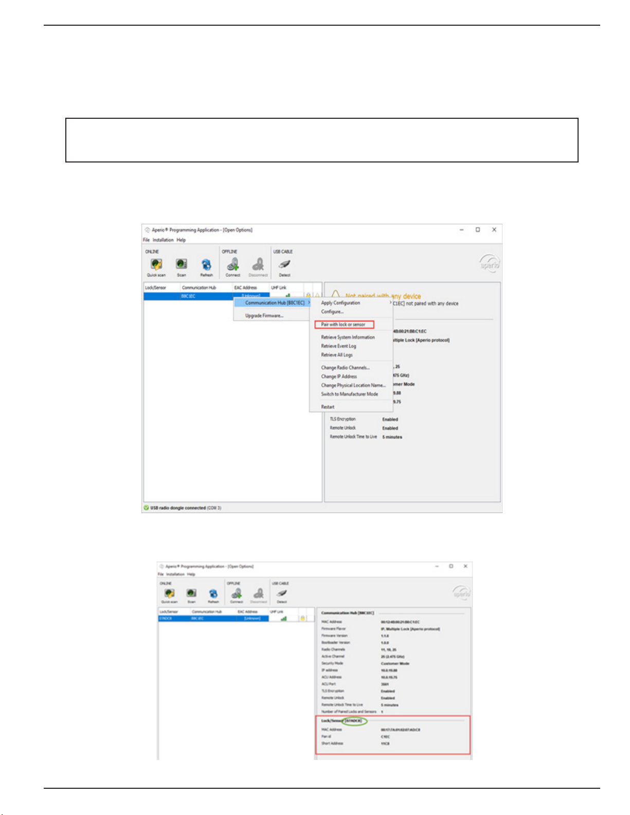
1. Open the Aperio® App, once in the App window and you have scanned for the AH40 hub, you can
then Right-Click and Select Communication Hub>Pair with lock or sensor from the options list as shown
below.
2. Verify that the Lock has been Discovered by the Hub and Note the Lock ID as seen in the green circle
below.
Prior to attempting to add a Lock, you will need to make sure that the lock has new
batteries, the Cover Plate has been properly secured and the lock is functioning properly
per manufacturers recommendations.
!
Integration Guide Page 12
Aperio Integration
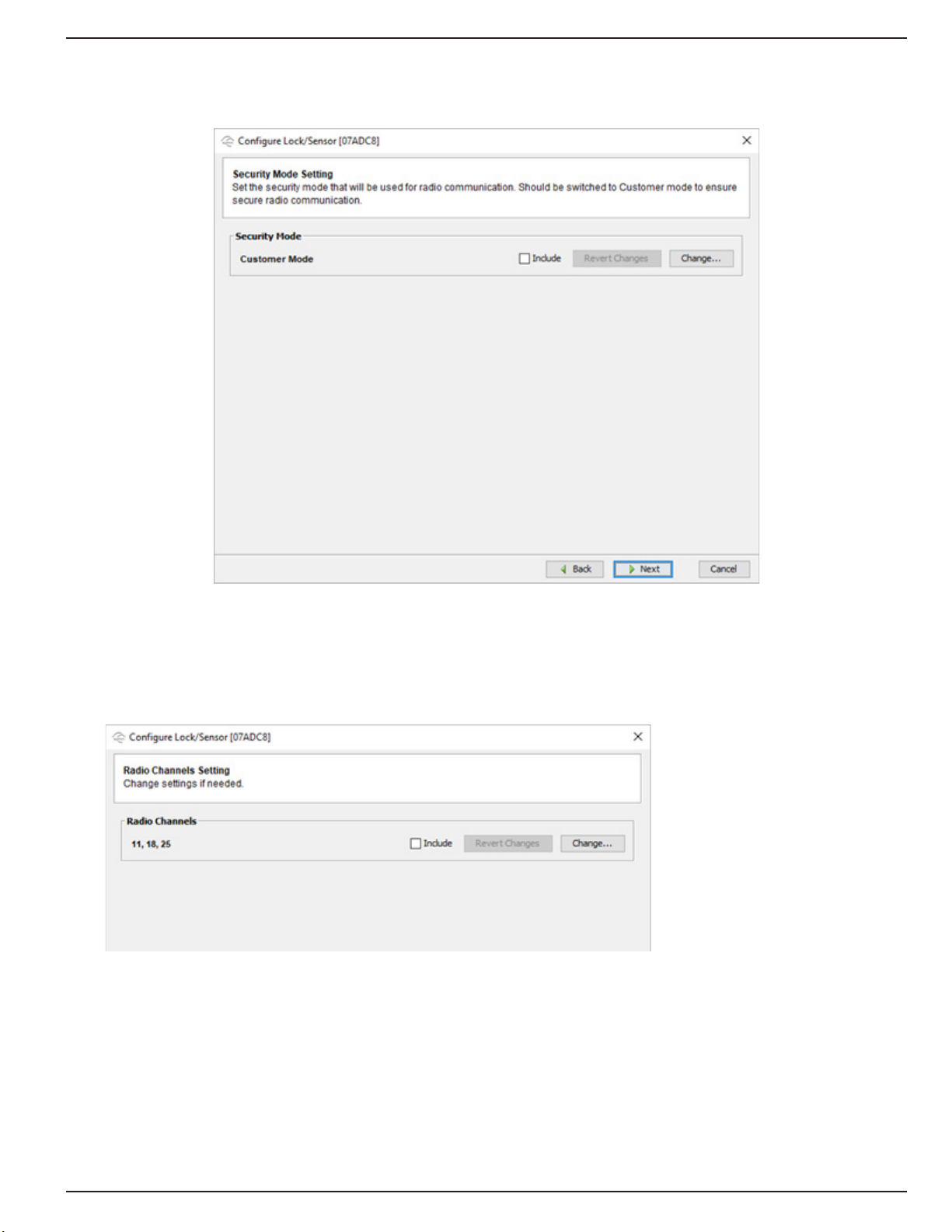
4. Right-Click on the Hub, Select Lock/Sensor>Congure to enter the lock or sensor conguration
window. Once in the Window, the lock will need to be Set to Customer Mode in Similar fashion as the Hub
as shown below.
5. Verify that the Lock or Sensor is on the Same Channels as the Hub has been congured to
communicate on. In this example, the channels are 11, 18, and 25. This allows for the segmenting of the
network communications within the Hub’s wireless network.
If performed correctly, the Hub status light will be Solid Green. If there is an error communicating between
the Hub and the Lock or Sensor, the Hub status light will begin to blink the Red LED Three Times. Next we
will import added Locks and Sensors into DNA.

Integration Guide Page 13
Aperio Integration
Conguring Locks in DNA Fusion
Once you have added the locks to the AH40 Hub, you can now import them into the Access Control
system. For this example, we will be adding the Locks added to the Hub inside of DNA Fusion.
1. Open DNA Fusion if the program is not already started. Once in DNA Fusion, you will need to Open the
Hardware Tree and perform a Right-Click on the Site and Select Refresh Status from the list.
2. Click on the Plus Sign to the Left of the AH40 Hub (Subcontroller) to display your attached devices.
Right-Click on the intended lock and Select Add Door>Create Aperio Door A new window will appear.
2. Type In the Lock ID (Hexidecimal Format) in the Reader Properties that was written down in Step 2
Page 11 in the Aperio Device ID as shown Below.
Once you have Clicked OK, you will now be able to test the connection and conguration by Swiping a
Badge with Known Access at the reader. You will be notied of the Transaction Event in the Events Viewer
as well as get the temporary unlock of the door per the Door reader conguration settings.

Integration Guide Page 14
Aperio Integration
Conguring Privacy Mode
Setting Up Privacy Mode can be done One of Two ways, the rst way consists of Double-Clicking on the
Reader requiring privacy mode, Select Door Objects, and then Select Privacy from the Drop-Down Menu
for Ext. Mode.
The second way consists of Right-Clicking the Door and Select Control>Extended>Set Privacy Mode.

Integration Guide Page 15
Aperio Integration
Regardless of the way chosen to implement Privacy Mode you will need to Open the Aperio Hardware App
(with Aperio USB plugged in) and Click on Congure Lock or Sensor>Privacy Mode Conguration. Once
the window is open, you will need to Click Change and Select Enabled.
The Privacy Mode allows the end user to press a button on the inside part of compatible locks that
overrides the lock sets’ function similar to a Lockdown situation until the user presses the button a second
time to allow the lock to go back to its normal state or function. For more information on this setting or to
check for compatibility contact your lock manufacturer.
Continued on the following page

Integration Guide Page 16
Aperio Integration
Technical Data
Physical Dimensions:
82 mm x 82 mm x 37 mm (H x W x T)
Power Supply:
8-24 VDC or Power over Ethernet (PoE)
Power Rating:
The power supply shall be able to deliver minimum, 1.2 W and be 3 A over current protected. Wire
requirements 16-22 AWG.
PoE IEEE 802.3.af compliant class 1 Powered device (PD)
Ethernet:
10BASE-T / 100BASE-TX Local Area Network
Radio Standard:
IEEE 802.15.4 (2400 – 2483,5 MHz), 16 channels (11-26), AES 128 bit encryption
Receiver Sensitivity:
-100 dBm
Wireless Transmit Power:
10 dBm/MHz. Peak value from average detector according to EN ETSI 300 328 Maximum spectral density.
Wireless Operating Range:
Indoors up to 25 m depending upon installed environment.
Internal Antenna:
Two port cross polarized patch antenna.
External Antenna:
One reverse polarity SMA external antenna connector. AH40 is certied to be used with ASSA ABLOY
external antenna AH ANTENNA 1. If other external antenna is used it must be of same type (dipole) and
not have larger antenna gain than 3.6 dBi.
Operating Temperature:
5 °C to 35 °C
Humidity:
< 95 % non-condensing
IP Classication:
IP20
Safety, Radio and EMC:
IEC 62368-1:2014, EN 62368-1:2014 + A11:2017
UL/CSA 62368-1:2014, EN 301 489-1 V2.1.1
EN 301 489-17 V3.2.0, EN 300 328 V2.2.2
EN 50130-4:2011 + A1:2014, EN 62311
FCC 47CFR Part 15 subpart B and subpart C, ISED RSS-247 and ICES-003
AS/NZS 4268
Table of contents
Popular Switch manuals by other brands


Inverto
Inverto Unicable IDLU-UST112-CUO1O-8PP installation manual

Avaya
Avaya IP Office IP401 installation manual

Crestron
Crestron 8x8 DigitalMedia DM-MD8X8 brochure

ANTAIRA
ANTAIRA LNX-1202G-SFP Series Quick installation guide

Intermatic
Intermatic GM40AVE-RD89 Series installation instructions

Brocade Communications Systems
Brocade Communications Systems 6505 Hardware reference manual


