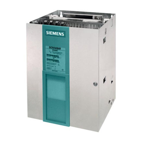
Acrel ARD3M User manual

428
428
428
428
ARD3M Intelligent motor Protector
Operating Manual V1. 2
ACREL Co., Ltd

DeclarationAll rights Reserve d. Without the written permission of the Company, the contents of any
paragraph or section in this manual shall not be copied, copied or disseminated in any form. Otherwise,
all consequences shall be borne by the violator.
Our company Reserve s all legal rights.
Our company Reserve s the right to modify the product specifications described in this manual
without prior notice. Before placing an order, please consult your local agent for new specifications of
this produ ct

Catalog
1、Overview ............................................................................................... 1
2、Product Features .................................................................................... 1
3
、
Model specification ............................................................................... 2
4
、
M ain parameters .................................................................................... 3
5、Dimensions and installation .................................................................. 6
6、Protection function description ........................................................... 1 3
7、Function Settings and instructions ...................................................... 2 7
8、Communication Settings and instructions .......................................... 4 8
9
、
Typical application scheme ................................................................. 9 6
10
、
Brief Introduction of Featured Functions ....................................... 100
11
、
Sample order ................................................................................... 1 06

- 1 -
1
1
1
1 Overview
Overview
Overview
Overview
The ARD3M intelligent motor protector (hereinafter referred to as the protector) is suitable for
low-voltage motor circuits with rated voltage up to 660V and integrates protection, measurement,
control, communication, operation and maintenance.Its perfect protection function ensures the
safe operation of the motor, with logic programmable function, can meet a variety of control
methods.Different communication modules can be selected to meet the needs of field
communication.
Product Implementation standards:
—— GB 14048.4-2010 Low-voltage switchgear and controlgear -- Part 4-1: Contactors and
motor starters -- Electromechanical contactors and motor starters (including motor protectors);
—— JBT 10736-2007 Low voltage motor protector.
2
2
2
2 Product
Product
Product
Product Features
Features
Features
Features
■ The auxiliary power type is optional. The AC220V power module supports the power range of
AC85-265V/DC100-300V and the AC380V power module supports the power range of
AC/DC100-415V.
■ Support fundamental and full-wave power parameter measurement (U, I,
P,
Q, S,
PF,
F,
EP,
EQ), voltage and current imbalance degree, voltage and current positive sequence, negative
sequence, zero sequence component, three-phase voltage phase a ngle, residual current, voltage
and current 2-63 sub-harmonic measurement, sub-harmonic inclusion rate and total harmonic
distortion rate.
■ Protection functions include overload inverse time, overload definite time, grounding, starting
a timeout, leakage, under load , locked-rotor, obstruction, short circuit, phase, overflow, imbalance
(current, voltage, power, less power, overvoltage, undervoltage, phase sequence, temperature, time,
external fault, tE starting number, running time, alarm, fault alarm.
■ 10 channels programmable DI input, the default use of DC24V power supply, or external
active wet contact can be selected (see the selection table).
■ 6 channels programmable DO output, to meet the direct starting,
Y
-△starting,
auto-transformer starting, and other starting modes, can be through the communication bus to
achieve the master station to the motor remote control "start/stop".
■ Optional anti-shaking function: support immediate restart of shaking power and restart of
voltage loss.
■ 2 MODBUS_RTU communication channels are standard, and PROFIBUS DPV1, Ethernet
and P rofinet communication modules are available for selection.
■ Optional 2 channels DC 4-20 m
A
analog output interface, connected with DCS system, can
realize the monitoring of field equipment.
■ With fault record, start record, stop record, DI displacement record, restart record and other
records of various events, you can view a number of motor operation and maintenance
information, and can record the motor operation record for 1-5 hours at the same time.
■ The display interface supports Chinese/English liquid crystal display
■ It supports exporting waveform record and event record data on usb flash disk, and can open
exporting event record file with EXCEL 。

- 2 -
■ WIFI function can be added when color LCD is optional, and relevant data of motor protector
can be viewed and set by connecting the WIFI via mobile phone or computer.
3
3
3
3、Model
Model
Model
Model Description
Description
Description
Description
ARD 3M
/
Display module (Table 4)
Additional functions (Table 3)
Current Specification (Table 2)
Switching type (Table 1)
Enterprise code + design serial number
The standard switch quantity of ARD3M is 10DI and 6DO, and the switch quantity type is shown
in Table 1:
Table 1
The correspond to relation between ARD3M current specification and the rated current and power
of the applicable motor is shown in Table 2:
Table 2
Protector current
specification (A)
Ratio
setting
Primary side coil
number of
transformer
Applicable scope of
motor (kW)
Suitable for motor
Rated current range
(A)
1
S upport
5 circle 0.12- 999 0.1- 5000
5 1 circle 0.12- 999 0. 5 - 5000
25
Does not
support
1 circle 3-11 6.3-25
100 1 circle 15-45 25-100
250 1 circle 55-132 63-250
800 1 circle 160-250 250-800
Additional features of ARD3M are shown in Table 3:
Table 3
Main switch classification Code
DI is the dry contact , and the external power supply of
DO is AC220V
K1
DI is the wet contact , the input is DC110V, and the
external power supply of DO is AC220V
K2
DI is the wet contact , the input is DC220V, and the
external power supply of DO is AC220V
K3
DI is the wet contact , AC220V input, and DO external
power supply is AC220V
K4

- 3 -
Additional f unction Code Additional f unction Code
2-63 harmonic voltages and currents H Waveform recording WR
Additional
Communi
cation
module
(Optional)
1 channel PROFIBUS
DPV1 communication
CP Anti - electric shock function SU
2 channel PROFIBUS
DPV1 communication
2CP Insulation monitoring Ri
Ethernet communication
(MODBUS TCP protocol )
MCE Electric leakage protection L
1 channel Profinet communication PNET Fault record SR
1 channel 4-20mA output M1 2 channel 4-20mA output M2
Wireless function (optional with color dot
matrix LIQUID crystal)
WIFI
See Table 4 for the ARD3M display module:
Table 4
Display module code
Black and white dot matrix LCD, module size 98 × 60,
opening 92 × 55 (unit mm)
60L 1
Color dot matrix LCD, module size 98 ×60 ,cut-out 92 ×
55 (Unit mm )
60L2
Remarks :
(1)The auxiliary power supply defaults to AC 220V. If AC 380V auxiliary power is needed,
please note the correspond to parameters when placing an order after communication with the
manufacturer.
(2)The current specifications of 100A and below shall be the same type of current transformer.
The transformer is equipped with a secondary line of about 1m. If you need special line length,
please contact the manufacturer. The 250A and 800A current specifications use two other types of
transformers with no secondary wires.See "External Dimensions and Installation" for the
dimensions of the transformer
(3)The standard display cable is a network cable with a length of 1.5m. 3 meters and 5 meters
are available for optional configuration.
You
can place an order and remark the correspond to
cable length.
(4)For customers who do not need display modules, a batch of optional several display modules
can be used as a programmer, or the configuration software provided by the manufacturer can be
used to configure parameters through computer software.
(5)The temperature measurement support sensor type is PTC or NTC.
(6)After selecting the leakage function (L), each protector shall be equipped with a leakage
transformer. Please refer to the "External Dimensions and Installation" section for the dimensions
of the leakage transformer. The leakage transformer is equipped with a secondary wire of
2m ± 10cm. If other lengths are needed, please contact the manufacturer.
4
4
4
4 M
M
M
M ain
ain
ain
ain parameters
parameters
parameters
parameters
4.1 Technical indicators
ARD3M technical indicators are shown in Table 5:

- 4 -
Table 5
4.2 Functional configuration
The ARD3M functional configuration is shown in Table 6
Table 6
Type
Function
Functional configuration
S tandard
function
Optional function
Protection
function
Fixed time overload √
Inverse time overload √
Starting timeout √
Phase loss √
V
oltage unbalance √
C urrent unbalance √
Locked- r otor √
under load √
Technical parameters Technical indicators
Protector auxiliary
power supply
Support two power modules, AC 220V power module
(AC85-265V/DC100-300V) default, AC 380V power module (AC/DC
100-415V) optional
Rated working
voltage of the motor
AC220V / 380V / 660V ,50Hz / 60Hz
Rated operating
current of the motor
1 (0.1A- 5000 A)
External current transformer
5 (0.1A- 5000 A)
25 (6.3A-25A )
100 (25A-100A )
250 (63A-250A )
800 (250A-800A )
Relay output contact
capacity
Impedance load AC250V 、10 A
Switching input
10 channels of passive dry contact (active DC110V, DC220V, AC220V
input can be optional)
C ommunication
Standard supplied 2 channel MODBUS RTU communication
Optional (only one can
be selected )
1-2 channel PROFIBUS DPV1 communication 、
1 channel PROFINET communication 、
Ethernet communication (MODBUS TCP
protocol )
E nvironment
Working temperature -10 º C ~55 º C
Storage temperature -25 º C ~70 º C
Relative humidity ≤ 95 ﹪No condensation, no corrosive gas
A ltitude ≤ 2000m
Pollution levels Class 3
Protection grade Main body IP20, split display module IP54 (installed on the cabinet panel)
Install ation category Level III

- 5 -
External fault √
B lock √
Temperature protection (PTC/NTC )√
R esidual current
grounding √
leakage √ (leakage )
Phase sequence √
Under voltage √
Over voltage √
Under powe r √
Over powe r √
tE Time protect √
Overflow protection √
Alarm of starting times √
Running time alarm √
Fault frequency alarm √
C ontrol
mode
Protect type
√
Manual mode
Two step model
Double speed mode
Star triangle three successive
Power Shake and start again √
Communica
tion
function
2 channel Modbus-RTU communication √
1-2 channel PROFIBUS DPV1
communication
√
1 channel PROFINET communication √
1- channel Ethernet communication
(dual network port)
√
WIFI function
√ (Optional with color dot
matrix LIQUID crystal)
Switching
input
10 DI √
Relay
output
6 DO √
Analog
output
1 channel DC4-20mA
√2 channe DC4-20mA
E vent log
Start record,stop record,DI displacement
record,restart record,operation record
(support communication transmission
and U disk export)
√
Waveform
recording
Record the current,voltage,DI/DO
waveform before and after the fault
trip,support communication
transmission and U disk export
√

- 6 -
Measureme
nt display
constant
value setting
M easured
parameters
Three phase current,three
phase line voltage,active
power,reactive
power,power
factor,frequency,active
power,reactive power,etc
√
2-63 rd current,voltage
harmonics,harmonic
inclusion rate,total
harmonic distortion rate
√
Fixed
value
setting
Various protected fixed
value queries
√
Various protection
Settings
√
Display unit
Liquid
crystal
display
(LCD)
Black and white dot
matrix LCD display
√Color dot matrix LIQUID
crystal display
5
5
5
5 Overall
Overall
Overall
Overall dimensions
dimensions
dimensions
dimensions and
and
and
and installation
installation
installation
installation
The product composition of ARD3M is shown in Figure 1, Figure 2 and Figure
FIG. 1 Composition of products with 100A and below specifications

- 7 -
FIG. 2 Composition of 250A and 800A
FIG. 3 Assembly diagram of main body and optional communication module
Note: When a single channel PROFIBUS_DP, Ethernet or PROFINET communication module is
selected, its combination with the main body is the same as that shown in Figure 3.
5 .1 Panel size and opening (Unit :mm )
5.1.1 60L1 The shape and opening size of the black and white LIQUID crystal display unit are
shown in Figure 4:
Front view Side view Back view

- 8 -
Disk cut-out size
Figure 4 60L1 shows the unit shape and hole size
5.1.2 The external dimensions of 60L2 color LIQUID crystal display unit are shown in Figure 5
(the dimensions of side view, rear view and opening are the same as those of 60L1 black and
white liquid crystal display unit) :
Figure 5 60L2 shows the external dimensions of the unit
5 .2 Size of main and additional Communication module (unit: mm)
5.2.1 The ARD3M main body is installed with 35mm guide rail, and its external dimensions are
shown in Figure 6:
Front view Side view
Figure 6 ARD3M main body dimensions
5.2.2 The external dimensions of PROFINET communication module, single-channel
PROFIBUS_DP communication module and Ethernet communication module are shown in Figure
7. Each communication module is installed with guide rail:

- 9 -
Front view Side View
Figure 7 Overall dimensions of PROFINET, single-channel PROFIBUS_DP
and Ethernet communication module
5.2.3 The size of the dual-channel PROFIBUS_DP communication module is shown in Figure 8.
The module is installed with guide rail:
Front view Side View
Figure 8 External dimensions of 2 -channel PROFIBUS_DP communication module
5 . 3 Transformer size
5. 3.1 The external dimensions of current transformers of 100A and the following specifications
are shown in FIG. 9 (unit: mm) : :
The current transformer with the current specification of the protector is 100A, with the standard
secondary connection line length of 1m ± 10cm. If other lengths are needed, please contact the

- 10 -
manufacturer, for example, 3m and 5m lines are optional. The secondary lines of yellow, blue, red
and black correspond to to the correlation of current A, B, C and the common end of the
transformer.
A
protector is equipped with
A
set of transformer.
FIG. 9 External dimensions of current transformers with specifications below 100A
5. 3.2 The external dimensions of the 250A current transformer are shown in FIG. 10 (unit: mm) :
The current specification of the protector is the current transformer matched at 250A. There is no
secondary connection wire. One protector is equipped with three transformers.
FIG. 10 External dimensions of current transformer 250A
5. 3.3 The external dimensions of the current transformer (800A) are shown in FIG. 11 (unit: mm) :
The current specification of the protector is 800A and the current transformer is not equipped
with secondary connection. One protector is equipped with three transformers.

- 11 -
FIG. 11 External dimensions of current transformer 800A
5. 3.4 The external dimensions of the leakage current transformer are shown in Figure 12 and Table
7 (unit: mm) :
The protectors with current specifications of 100A and below are equipped with leakage current
transformers with specifications of L-45.250A and current protector with specifications
L-80 leakage current transformer;800A and current specification protector with L-150 leakage
current transformer.The leakage transformer is equipped with a secondary wire of 2m ± 10cm. If
other lengths are needed, please contact the manufacturer.
FIG. 12 External dimensions of leakage current transformer
Table 7
Type
Spec
Overall
size (mm)
Go through
size (mm)
Installation
size (mm)
T
oler
ance (
mm)
W
eight
(g)W H D Φ M N Φ 2
L-45 75 75 22 46 65 65 4
± 1
200 ± 10
L-80 120 120 23 81 105 105 4 380 ± 20
L-150 196 205 24 150 175 180 6 850 ± 50
5.4
T
erminal

- 12 -
The wiring terminal arrangement of the ARD3M main body is shown in Figure 13:
F IG. 13 ARD3M terminal arrangement
Table 8 shows the ARD3M terminal number and function definition:
Table 8
Termina
ls no.
Function definition Remark
1 Power input L (+ at DC time)
The auxiliary power supply is
connected to the two terminals2 Power input N (- at DC time)
3 Un input
Three-phase voltage input4 Ua Phase voltage input

- 13 -
5 Ub Phase voltage input
6 Uc Phase voltage input
7、8 DO1 ,Start 1 output
6-channel programmable relay
output (DO)
(The function is defined as factory
default setting, which can be set by
users according to their needs)
9、10 DO2 ,Start 2 output
97 、98 DO 3 ,Trip output, normally open point signal
95 、96 DO 4 ,Trip output, normally closed signal
11 、12 DO 5 ,Circuit breaker output
91 、92 DO6 ,Alarm output
13 DI1 ,Start 1 signal input
10- channel programmable
Switching input (DI)
(The function is defined as factory
default setting, which can be set by
users according to their needs)
14 DI2 ,Start 2 signal input
15 DI3 ,Stop signal input
16 DI4 ,Reset signal input
17 DI5 ,Emergency stop signal input
18 DI6 ,External fault signal input
19 DI7 ,Control permission 1 input
20 DI8 ,Control permission 2 input
21 DI9 ,ordinary DI
22 DI10 ,ordinary DI
23 COM2 ,DI Input common terminal
34 The first analog output AO1+
2-channel 4-20mA analog output35 The second analog output AO2+
36 Analog output common end AO-
25 A1
first channel MODBUS
communication26 B1
28 A2
second channel MODBUS
communication29 B2
3 0 、31 R Insulation resistance detection
32 T1 (PTC input A )
Temperature protection (thermistor
input)33 T2 (PTC input B )
4 0 I L *
Leakage current measurement41 IL
42 COM3( current enters the common terminal )
Three phase current input43 Ia Phase current input
44 Ib Phase current input
45 Ic Phase current input
6
6
6
6 Protection
Protection
Protection
Protection function
function
function
function description
description
description
description
The default action stages of each protection are shown in Table 9 :
Table 9
Protection type
Default active
period

- 14 -
Overvoltage,undervoltage,voltage imbalance,phase sequence,external
fault,overflow protection,starting times,fault times,running time,PTC/NTC
temperature protection,insulation monitoring
whole course
Reverse time overload,blocking, phase break,leakage,grounding,starting
timeout,short circuit,overflow protection,Overvoltage,undervoltage,voltage
imbalance,phase sequence,external fault,number of starts,number of
faults,running time,PTC/NTC temperature protection,fixed time
overload,insulation monitoring
When starting
Reverse time-limit overload,blocking, phase break,current
imbalance,leakage,grounding,constant time-limit overload, under load ,short
circuit,overflow protection,overvoltage,undervoltage,voltage unbalance,phase
sequence,underpower,overpower,external fault,PTC/NTC temperature
protection,number of starts,number of faults,running time, i nsulation monitoring
In operation
6.1 Inverse time overload protection
When the motor runs for a long time in excess of its rated current under excessive load, it
will overheat the motor, reduce insulation and burn it out. The protector calculates the heat
capacity of the motor according to its heating characteristics and simulates its heating
characteristics to protect the motor.
The starting condition of reverse time-limit overload protection is that the maximum three-phase
current reaches the set overload starting value, and the default overload starting value is 1.2 times
the motor's rated current.
The current-time comparison table of overload protection is shown in Table 10, and the overload
characteristic curve (K curve) is shown in Figure 14:
Table 10
Optional
tripping curve
grade K
1 2 3 5 10 15 20 25 30 35 40
Tripping delay
(S)tolerance
± 10%
Three - phase balanced load, starting from the cold state
Rated value
Ie × 1.2
25 50 75 125 250 375 500 625 750 875 1000
× 1.5 16 32 48 80 160 240 320 400 480 560 640
× 2 9 18 27 45 90 135 180 225 270 315 360
× 3 4 8 12 20 40 60 80 100 120 140 160
× 4 2.26 4.52 6.78 11.3 22.5 33.8 45 56.3 67.5 78.8 90
× 5 1. 44 2.88 4.32 7.2 14.4 21.6 28.8 36 43.2 50.4 57.6
× 6 1 2 3 5 10 15 20 25 30 35 40
× 7.2 0.7 1.4 2.1 3.5 6.9 10.4 13.9 17.4 20.8 24.3 27.8

- 15 -
0
100
200
300
400
500
600
700
800
900
1000
Ie × 1.2 × 1.5 × 2 × 3 × 4 × 5 × 6 × 7.2 × 8
FIG. 14 Characteristic curve of overload (K curve)
Inverse time overload protection improves manual and automatic reset options. When "automatic"
is selected, after the overload trip of the motor, the heat capacity will be automatically reset to less
than 15%, and the restart operation can be allowed without the need for further reset
operation;When "manual" is selected, after the motor overload trip, the heat capacity will be
reduced to less than 15%. Manual manual reset is required, otherwise the restart operation is not
allowed.
Note:
Imax : Maximum three-phase current
In : Rated current
Heat : Percentage heat capacity
Hs : Heat capacity alarm value
6.2 Start overtime protection
When the starting time of the motor reaches the starting time set by the user, the average
three-phase current does not drop below the set tripping threshold, trigger the starting timeout
protection, issue tripping command, and stop the motor operation.For the increased safety motor,
the starting time setting shall not exceed 1.7 times tE time.

- 16 -
Note:
Iav : Three-phase mean current
Is : Set trip threshold
T
s:S tarting time
6.3 Locked-rotor protection
In the process of starting, if the motor shaft is stuck due to excessive load or mechanical reasons,
and the fault is not removed in time, the motor will overheat and the insulation will be reduced
and the motor will be burned out.The lock ed-rotor protection is applicable to the motor when such
faults occur in the starting stage. When the average current percentage reaches the set threshold,
the protector will trip or alarm within the set time in time to avoid the motor burning out.
Note:
Iav : Three-phase mean current
Is1 : Alarm action threshold
Is2 : Tripping threshold
Ts1 : Alarm action delay time
Ts2 : Delay time of trip action

- 17 -
6.4 Blocking protection
During the operation of the motor, if the motor shaft is stuck due to excessive load or mechanical
reasons, and the fault is not removed in time, the motor will be overheated and the insulation will
be reduced and the motor will be burned out.The blocking protection is applicable to protect the
motor when such faults occur in the running stage. When the average current reaches the set
threshold, the protector will trip or alarm within the set time in time to avoid the motor burning
out 。
Note:
Iav : Three-phase mean current
Is1 : Alarm action threshold
Is2 : Tripping threshold
Ts
: Alarm action delay time
6.5 under load protection
The protector provides under load protection when the motor is loaded with pumping load. When
the average three-phase current is lower than the set value, the protector should trip or alarm
within the set time.
Note:
Iav: Three-phase mean current
Is1: Alarm action threshold
Is2: Tripping threshold
Table of contents