manuals.online logo
Brands
  1. Home
  2. •
  3. Brands
  4. •
  5. M-system
  6. •
  7. Surge Protector
  8. •
  9. M-system MDCAT-A Series User manual

M-system MDCAT-A Series User manual

5-2-55, Minamitsumori, Nishinari-ku, Osaka 557-0063 JAPAN
Phone: +81(6)6659-8201 Fax: +81(6)6659-8510 E-mail: info@m-system.co.jp
EM-8165 Rev.0 P. 1 / 4
INSTRUCTION MANUAL
BEFORE USE ....
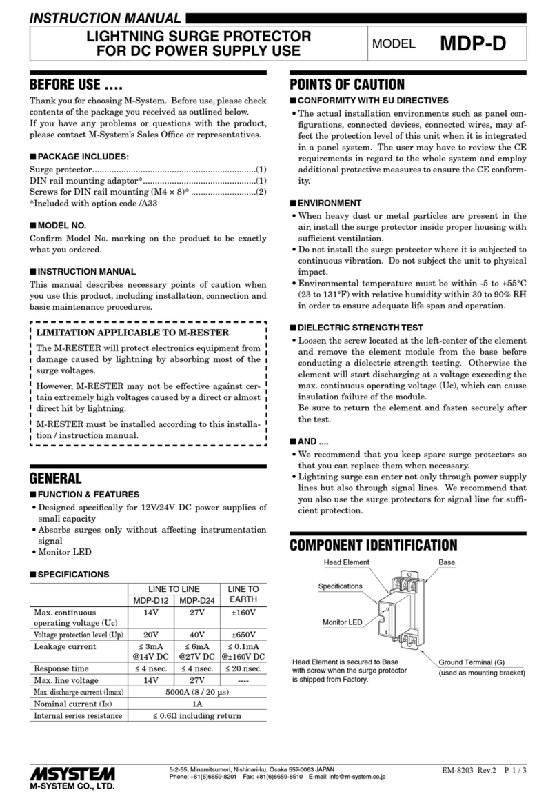
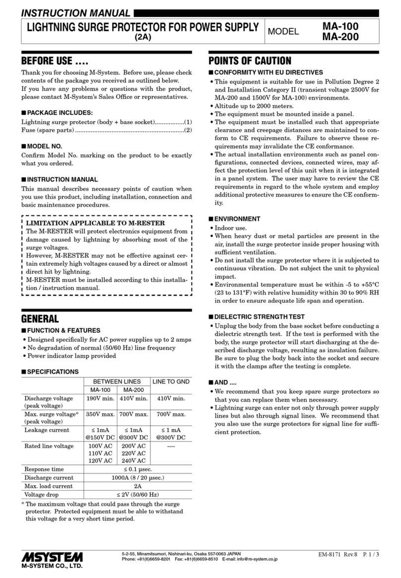
Thank you for choosing M-System. Before use, please check
contents of the package you received as outlined below.
If you have any problems or questions with the product,
please contact M-System’s Sales Office or representatives.
■PACKAGE INCLUDES:
Surge protector....................................................................(1)
LAN cable ............................................................................(1)
Single mount DIN rail ........................................................(1)
(Only for option code ‘/DR’ selected)
■MODEL NO.
Confirm Model No. marking on the product to be exactly
what you ordered.
■INSTRUCTION MANUAL
This manual describes necessary points of caution when
you use this product, including installation, connection and
basic maintenance procedures.
LIMITATION APPLICABLE TO M-RESTER
The M-RESTER will protect electronics equipment from
damage caused by lightning by absorbing most of the
surge voltages.
However, M-RESTER may not be effective against cer-
tain extremely high voltages caused by a direct or almost
direct hit by lightning.
M-RESTER must be installed according to this installa-
tion / instruction manual.
POINTS OF CAUTION
■ENVIRONMENT
• Indoor use. Install the unit on a place where the check
button and indicator LEDs can be easily visible and ac-
cessible.
• DANGER!
DO NOT perform an installation, wiring and mainte-
nance of the MDCAT-A duting thunder storms.
• When heavy dust or metal particles are present in the
air, install the surge protector inside proper housing with
sufficient ventilation.
• Do not install the surge protector where it is subjected to
continuous vibration. Do not subject the unit to physical
impact.
• Environmental temperature must be within -10 to +55°C
(14 to 131°F) with relative humidity within 5 to 95% RH
in order to ensure adequate life span and operation.
• This unit can be earthed via a DIN rail. Oxide film on the
surface of an aluminum rail may lower the electric con-
ductivity between this module and the ground. When this
unit is earthed via a DIN rail, use a steel or copper rail.
• Steel rails may be coated with thin oxide film. Discharg-
ing surge current may produce sparks with the film.
However, this does not affect the surge protection. If you
need to avoid sparks, prior to mounting on the DIN rail,
remove the film by a wire brush.
• Single mount DIN rail for option code ‘/DR’ is made of alu-
minum. Connect to ground with ground terminal when
this DIN rail is used.
■AND ....
• We recommend that you keep spare surge protectors so
that you can replace them when necessary.
• Lightning surge can enter not only through signal lines
but also through power supply lines. We recommend that
you also use the surge protectors for power line for suf-
ficient protection.
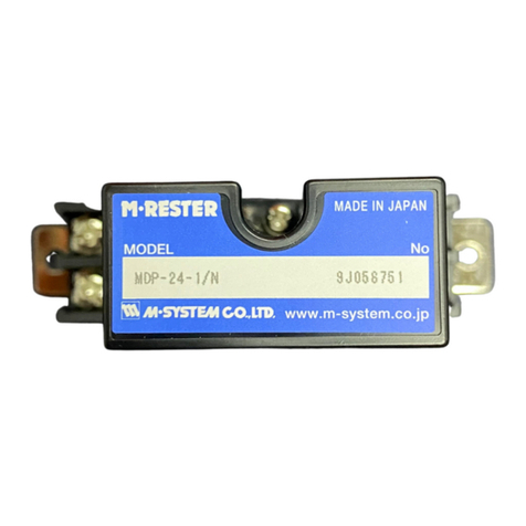
COMPONENT IDENTIFICATION
MODULAR JACK,
SURGE SIDE
ALMIndicatorLED
BATIndicatorLED
MODULAR JACK,
PROTECTED SIDE
CHKCheckButton
Specifications(side)
SHIELD TERMINAL (SHLD)
■FRONT VIEW
■REAR VIEW
EARTH TERMINAL (G)
SHORTCIRCUIT BAR
LIGHTNING SURGE PROTECTOR FOR ETHERNET
(PoE / 10 BASE-T / 100 BASE-TX / 1000 BASE-T, life monitor)
MODEL MDCAT-A
MDCAT-A
5-2-55, Minamitsumori, Nishinari-ku, Osaka 557-0063 JAPAN
Phone: +81(6)6659-8201 Fax: +81(6)6659-8510 E-mail: info@m-system.co.jp
EM-8165 Rev.0 P. 2 / 4
INSTALLATION
Mount the unit on a DIN rail. Once installed, do not move it to another DIN rail.
■MOUNTING THE UNIT ON A DIN RAIL
A)Hang the upper hook of the DIN rail mounting adaptor at
the rear side of unit, on the DIN rail.
B)Push in the lower in keeping pressing the unit to the DIN
rail.
DIN Rail
B
A
■REMOVING THE UNIT
A)Pull down the DIN rail adaptor utilizing a minus screw-
driver.
B)Pull out the lower part of the unit.
C)Detach the upper part from the DIN rail.
CB
A
DIN rail adaptor
GENERAL
■FUNCTION & FEATURES
• Designed specifically for Ethernet network
• Conforms with 1000 Base-T, PoE and PoE Plus
• LAN cable’s shield wire can be floating or grounding by a shortcircuit bar
• Pressing CHK (Check) button confirms with LEDs the life span of the surge protect device
• DIN rail mounting
■SPECIFICATIONS
LINE TO LINE (pair) LINE
TO
LINE (PoE)
LINE
TO
EARTH
MDCAT-A-5E MDCAT-A-6
Max. continuous operating voltage (Uc) ±6V ±3.3V ±58V ±150V
Voltage protection level (Up) ±15V @2kV ±10V @2kV ±100V @2kV ±600V @4kV
Leakage current @Uc 25µA 5µA 25µA 5µA
Max. discharge current (Imax) 100A 100A 100A 10kA
Nominal current (IN) 1A
Series resistance Approx. 0Ω
Insertion loss ≤ 3dB
Transmission performance: TIA/EIA-568-B.2
CAT5e (MDCAT-A-5E)
CAT6 (MDCAT-A-6)
MDCAT-A
5-2-55, Minamitsumori, Nishinari-ku, Osaka 557-0063 JAPAN
Phone: +81(6)6659-8201 Fax: +81(6)6659-8510 E-mail: info@m-system.co.jp
EM-8165 Rev.0 P. 3 / 4
TERMINAL CONNECTIONS
Connect the unit as in the diagram below.
■EXTERNAL DIMENSIONS unit: mm (inch)
• When mounting, no extra space is needed between units.
38 (1.50)
90 (3.54)3.5 (.14)

DIN RAIL
(35mm wide)
[3 (.12)]
11
(.43)
50 (1.97)
4.2 (.17)
35 (1.38)
7.3 (.29)
40 (1.57)
MODULAR JACK,
SURGE SIDE
MODULAR JACK,
PROTECTED SIDE
SHIELD TERMINAL (SHLD)
■UNIT
■DIN RAIL
2-M3 SCREW
EARTH TERMINAL (G)
SHORTCIRCUIT BAR
35 (1.38)
6 (.24) [4.5 (.18) deep]
■CONNECTION DIAGRAM
■ PROTECTING STP DEVICE
*
3
*
3
■ PROTECTING NON-STP (UTP) DEVICE
MDCAT-A (Protected Device)
Crossover Wire
FG
*
2
*
7
*
5
*1. Unshield twisted-pair cable
*2. Maintain the shortcircuit bar. The protected device is earthed.
*3. Cable included in the product package or provided by customer.
*4. Shield twisted-pair cable
*5. STP cable’s shield wire serves as the crossover wiring.
*6. The protected device is ‘earthed’ when the shortcircuit bar is connected. Remove the bar in order to switch to ‘floating’ state.
*7. Use a DIN rail made of steel or copper when connecting to ground via the DIN rail.
Single mount DIN rail for option code ‘/DR’ is made of aluminum.
Connect to ground with ground terminal when this DIN rail is used.
MDCAT-A (Protected Device)
FG
*
6
*
7
SHLD
G
SHLD
G
UTP Cable
*
1
STP Cable
*
4
MDCAT-A
5-2-55, Minamitsumori, Nishinari-ku, Osaka 557-0063 JAPAN
Phone: +81(6)6659-8201 Fax: +81(6)6659-8510 E-mail: info@m-system.co.jp
EM-8165 Rev.0 P. 4 / 4
■NETWORK CONNECTION EXAMPLE
Hub / Switch
Server
Protocol
Converter
Remote I/O
Remote I/O
Router
MDCAT−A
PC
Open Field Network Network Camera
STATUS INDICATION
Press check button to indicate the status of internal dis-
charge element.
■INDICATORS
Activated by CHK (Check) button, see the status table
shown below.
BAT: Green LED
ALM: Red LED
CHK button: Push button; momentary
BAT ALM BATTERY DISCHARGE
ELEMENT
REPLACEMENT
ON OFF Normal No Need
ON ON Normal Near End Near
OFF ON Normal End of Life Immediately
Required
OFF OFF Discharged Unable to Judge
CHECKING
■WIRING
• Make sure that wiring is done as instructed in the con-
nection diagram.
• Make sure that the Earth terminal is connected to the
metallic housing of protected device.
• Make sure that the Earth terminal is connected to earth.
MAINTENANCE
Even lightning in remote locations could induce surges
without our knowledge. Regular checking of the surge
protector is important to find degradations in early stage,
before and after the storm seasons, and whenever you ex-
perience a strong lightning storm. Checking procedure is
explained in the following:
■CHECKING EXTERIOR
If discoloration or deformation is observed, replace with a
new one immediately.
■CHECKING
COMMUNICATION
Check the communication status is improved or not by re-
moving the device when the communication is unstable or
stopping. Replace with a new one if the device is not recov-
ered.
DISCHARGE ELEMENT
For testing, press CHK (Check) button on the front and
LEDs turn on or off according to the surge protector’s condi-
tion. When replacement is required, replace the module to
a new one immediately. Refer to the table for judgement.

This manual suits for next models

2

Other M-system Surge Protector manuals

M-system MH-1201 User manual

M-system

M-system MH-1201 User manual

M-system MDP-24T User manual

M-system

M-system MDP-24T User manual

M-system MD73W User manual

M-system

M-system MD73W User manual

M-system MAL-230x User manual

M-system

M-system MAL-230x User manual

M-system MD7FB User manual

M-system

M-system MD7FB User manual

M-system MDP-JS User manual

M-system

M-system MDP-JS User manual

M-system MD7PM User manual

M-system

M-system MD7PM User manual

M-system MATP User manual

M-system

M-system MATP User manual

M-system MD7JS User manual

M-system

M-system MD7JS User manual

M-system MD7PA User manual

M-system

M-system MD7PA User manual

M-system MDCAT-SPE-A User manual

M-system

M-system MDCAT-SPE-A User manual

M-system MAKN User manual

M-system

M-system MAKN User manual

M-system MDA-TL User manual

M-system

M-system MDA-TL User manual

M-system MDR2 User manual

M-system

M-system MDR2 User manual

M-system MD7PL User manual

M-system

M-system MD7PL User manual

M-system MDPA-24 User manual

M-system

M-system MDPA-24 User manual

M-system MD7LWA User manual

M-system

M-system MD7LWA User manual

M-system MD6 24 Series User manual

M-system

M-system MD6 24 Series User manual

M-system MDP-65T User manual

M-system

M-system MDP-65T User manual

M-system MGA-100 User manual

M-system

M-system MGA-100 User manual

M-system MMAH Series User manual

M-system

M-system MMAH Series User manual

M-system MD7G User manual

M-system

M-system MD7G User manual

M-system MDPA-24 User manual

M-system

M-system MDPA-24 User manual

M-system MD6x-24 User manual

M-system

M-system MD6x-24 User manual

Popular Surge Protector manuals by other brands

Patton electronics 537 user manual

Patton electronics

Patton electronics 537 user manual

Monacor AHVB-240BNC quick start guide

Monacor

Monacor AHVB-240BNC quick start guide

Sentinel MCG 120M installation instructions

Sentinel

Sentinel MCG 120M installation instructions

Emerson SolaHD STC-642 Series quick start guide

Emerson

Emerson SolaHD STC-642 Series quick start guide

Panamax MFP500-EX instructions

Panamax

Panamax MFP500-EX instructions

Trust 210 quick start guide

Trust

Trust 210 quick start guide

Tripp Lite TLP810NET Specifications

Tripp Lite

Tripp Lite TLP810NET Specifications

Tripp Lite ISOBLOK2-0 owner's manual

Tripp Lite

Tripp Lite ISOBLOK2-0 owner's manual

Rocket Fish RF-HTS120 Guía De Instalación Rápida

Rocket Fish

Rocket Fish RF-HTS120 Guía De Instalación Rápida

Tripp Lite SUPER6OMNI Series owner's manual

Tripp Lite

Tripp Lite SUPER6OMNI Series owner's manual

Tripp Lite TLP606 Specifications

Tripp Lite

Tripp Lite TLP606 Specifications

Tripp Lite SPIKECUBE Specifications

Tripp Lite

Tripp Lite SPIKECUBE Specifications

Rocket Fish RF-HTS120 Guide d'installation rapide

Rocket Fish

Rocket Fish RF-HTS120 Guide d'installation rapide

Tripp Lite SK6-0B Specifications

Tripp Lite

Tripp Lite SK6-0B Specifications

Torus Power RM Series manual

Torus Power

Torus Power RM Series manual

Tripp Lite ISOTEL4ULTRA Specifications

Tripp Lite

Tripp Lite ISOTEL4ULTRA Specifications

Rocket Fish RF-HTS1215 Quick setup guide

Rocket Fish

Rocket Fish RF-HTS1215 Quick setup guide

Tripp Lite IBAR12/20ULTRA AGIB120V20SSRM Specifications

Tripp Lite

Tripp Lite IBAR12/20ULTRA AGIB120V20SSRM Specifications

manuals.online logo
manuals.online logoBrands
  • About & Mission
  • Contact us
  • Privacy Policy
  • Terms and Conditions

Copyright 2025 Manuals.Online. All Rights Reserved.