manuals.online logo
Brands
  1. Home
  2. •
  3. Brands
  4. •
  5. Siemens
  6. •
  7. Surge Protector
  8. •
  9. Siemens SP-37 Maintenance and service guide

Siemens SP-37 Maintenance and service guide

1
Installation &
Maintenance
Power Line Surge
Protector
Model
SP-37
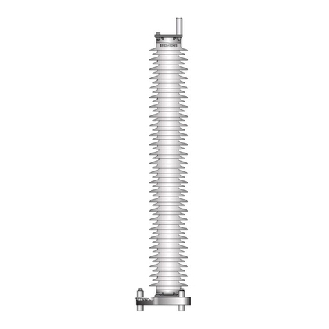
INTRODUCTION
The SP-37 is a secondary surge protector
des
i
gned
to be mounted on a load center at the
power
service
entrance
.
It offers a gap-type arrestor and is easily wired into
exis
t
i
ng
systems
.
It
has
no exposed
terminals.
INSTALLATION
The SP-37 must be mounted horizontally as
shown.
•Never mount the SP-37
vertically
.
The arrestor may not "clear" properly if mounted in the vertical
position.
•The SP-37 should never be mounted
w
i
th
the
vent holes
obstructed.
•This
un
i
t
is only for use in areas
protected
from
the
weather, such as inside a bungalow or
equipment
ca
se
.
•Never install on the "line" side of a branch breaker on a
load
cen
t
er.
WHITE
022701-29X
BLACK
010900-53X
RED
010802-7X
Siemens Industry, Inc., Rail Automation
2400 Nelson Pkwy.,Louisville KY
I&M 010836-7
Revised 11/95, 6/00, 8/14
Doc. No.: SIG-00-00-09 Version A.1
Doc.
Version:
2
PROCEDURES
WARNING
HIGH VOLTAGES ARE PRESENT. TURN OFF POWER
BEFORE INSTALLATION OR
SERVICING
.
The use of temporary ground
dur
i
ng
installation and maintenance is
recommended.
1) Install one washer over the threads at the end of the SP-37
housing
.
Push the washer
up
against the
housing
.
2) Choose a knockout in the load center that is a distance from the backboard that
will
allow
the back of the SP-37 to lay flat against the
backboard
.
3) Install the second washer on the threads at the end of the SP-37 housing from
inside
the
load center. Install the lock nut so that
i
t
loosely holds the SP-37 in
place.
4) Use the wood screw provided to secure the SP-37 mounting tab to the
backboard
.
5) Tighten the lock nut installed in step 3 for a snug
fit.
6) Cut the wires on the SP-37 to the
m
i
nimum
usable
length.
Do not coil the wires as
this
greatly reduces SP-37 performance. Also, avoid kinks and sharp bends in the
wiring
.
7) Connect the wires to the load center, observing the proper hook-up
scheme.
8) The wires must be connected so that there is a fuse or circuit breaker between the
SP-37
and the power service
line
.
HOOK UP
SCHEMES
NOTE: 1) 20 amp maximum current for each
SP-37
2) Do not use SP-37 in a circuit with voltage of more than 120 V
rms
.
Doc.
Version:
3
MAINTENANCE
The SP-37 requires no regular
maintenanc
e
.
Over time, with repeated surges, the
power-line
protector inside will become
damaged
.
It can be inspected visually through
the clear
plastic
housing
and,
if blackened or burned, should be replaced as described
below.
CAUTION
DO NOT INSERT ANY OBJECTS INTO THE VENT HOLES OF
THE
SP-37.
SERVICING
The
power-line
protector can be replaced as
follows:
1) Turn off all power to the load center at the main
breaker
.
Make sure power is
of
f
.
2) Disconnect the SP-37 wires from the load
cente
r
.
3) Remove the two screws holding the cover on the
SP-37
.
4) Remove the nuts holding the protector in place and remove the
protector
.
5) Install the new
protector.
6) Reinstall nuts removed in step 4 and tighten nuts to hold the new protector in
place.
7) Reinstall the cover and secure with the screws removed in step
3.
8) Reconnect the SP-37 wires to the load
center -
observe correct
hookup.
9) Restore power to the load
center.
REPLACEMENT
PARTS
To Order: Specify Description and Part
Number
Item
No.
Part
No.
D
escription
Qty.
1
010836-1
Protector
H
ousing
1
2
0
223
12
-
11
-
7X
Wire
12
Ga. Black x 24"
w
/
T
erminal
1
3
022312-18-2X
Wire 12 Ga.White x 28"wiT
erm
inal
1
4
022312-9-1X
Wire 12 Ga. Red x 23"
w/Terminal
1
5
010836-5
Rubber Grommet
B
ushing
1
6
02270
1-
29X
Power Line Protector
1
7
023690-1
4
A
B
eve
l
ed
Washe
r
6
8
023690-14
Cal mp Nut
7
9
010900-53X
150 Volt Varistor Assembly
1
10
01000
1
-9
1
/
2
ID Rubber Grommet
1
11
010802-
7
X
Choke Coil Asse
m
bl
y
1
12
18-00-090
Wire Marker "
I
n
"
1
1
3
18-00-091
Wire Marker "Out"
1
14
010836-2
Box Cover
1
15
5283
Tap Screw Phil #8 x
1
/2
2
16
010836-3
Warning
L
abe
l
1
17
010837-4
Part ID
L
abel
1
18
7152
Loc Nut
3/4"
1
19
1742-SC
Flat
Washer
1 x
2-1/2
2
20
5733
-R
SC
Wood Screw RD #10 x
1-1/4
1
21
2355
Wire
Nut Type Y
1

Other Siemens Surge Protector manuals

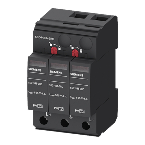
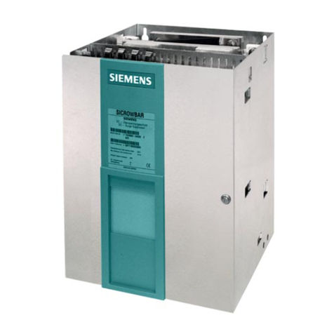
Siemens 5SD7483-6RC User manual

Siemens

Siemens 5SD7483-6RC User manual
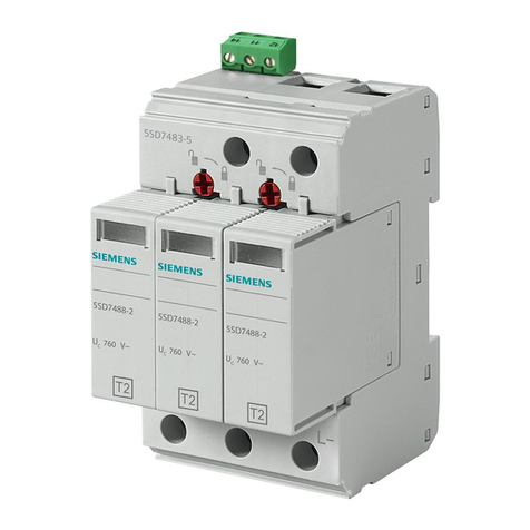
Siemens 5SD7483-5 User manual

Siemens

Siemens 5SD7483-5 User manual

Siemens 5SD7418 Series User manual

Siemens

Siemens 5SD7418 Series User manual

Siemens TPS3 User manual

Siemens

Siemens TPS3 User manual

Siemens 5SD7 413-2 User manual

Siemens

Siemens 5SD7 413-2 User manual

Siemens TPS3 12 User manual

Siemens

Siemens TPS3 12 User manual

Siemens 5SD7 502-0KB User manual

Siemens

Siemens 5SD7 502-0KB User manual

Siemens TPS3 03 DC User manual

Siemens

Siemens TPS3 03 DC User manual

Siemens SP-36 Maintenance and service guide

Siemens

Siemens SP-36 Maintenance and service guide

Siemens 3TX7462-3 User manual

Siemens

Siemens 3TX7462-3 User manual

Siemens 5SD7483-5 User manual

Siemens

Siemens 5SD7483-5 User manual

Siemens BSPD 100 Series User manual

Siemens

Siemens BSPD 100 Series User manual

Siemens HNM3M120 User manual

Siemens

Siemens HNM3M120 User manual

Siemens TPS3 03 User manual

Siemens

Siemens TPS3 03 User manual

Siemens 5SD7 502-0 User manual

Siemens

Siemens 5SD7 502-0 User manual

Siemens 5SD7461-0 User manual

Siemens

Siemens 5SD7461-0 User manual

Siemens 3TX6446-1 Series User manual

Siemens

Siemens 3TX6446-1 Series User manual

Siemens 5SD7418-2 User manual

Siemens

Siemens 5SD7418-2 User manual

Siemens SPD4home User manual

Siemens

Siemens SPD4home User manual

Siemens 3TX7402-3A User manual

Siemens

Siemens 3TX7402-3A User manual

Siemens 5SD7 498-3 User manual

Siemens

Siemens 5SD7 498-3 User manual

Siemens 5SD7463-0 User manual

Siemens

Siemens 5SD7463-0 User manual

Siemens TPS 9 User manual

Siemens

Siemens TPS 9 User manual

Siemens 5SD7434-1 User manual

Siemens

Siemens 5SD7434-1 User manual
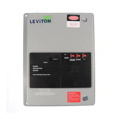
Popular Surge Protector manuals by other brands
Acoustic Research PW1000 quick start guide

Acoustic Research

Acoustic Research PW1000 quick start guide

Nitek CAMUTP24 installation manual

Nitek

Nitek CAMUTP24 installation manual

Intermatic IG1240RC user manual

Intermatic

Intermatic IG1240RC user manual

Mersen STLBT23-10 installation instructions

Mersen

Mersen STLBT23-10 installation instructions

Trust 210 quick start guide

Trust

Trust 210 quick start guide

Rocket Fish RF-HTS130 Guide d'installation rapide

Rocket Fish

Rocket Fish RF-HTS130 Guide d'installation rapide

Tripp Lite ISOTEL4ULTRA Specifications

Tripp Lite

Tripp Lite ISOTEL4ULTRA Specifications

FRO­NIUS SPD Installation instruction

FRO­NIUS

FRO­NIUS SPD Installation instruction

Tripp Lite isobar IBAR4ULTRAUSBB owner's manual

Tripp Lite

Tripp Lite isobar IBAR4ULTRAUSBB owner's manual

Tripp Lite ISOBAR12ULTRA AGIB120V12SSRM Specification sheet

Tripp Lite

Tripp Lite ISOBAR12ULTRA AGIB120V12SSRM Specification sheet

Tripp Lite ISOTEL4ULTRA Specifications

Tripp Lite

Tripp Lite ISOTEL4ULTRA Specifications

Rocket Fish RF-HTS1615 Quick setup guide

Rocket Fish

Rocket Fish RF-HTS1615 Quick setup guide

Rocket Fish RF-HTS110 Guía De Instalación Rápida

Rocket Fish

Rocket Fish RF-HTS110 Guía De Instalación Rápida

Tripp Lite B110-SP-HDMI quick start guide

Tripp Lite

Tripp Lite B110-SP-HDMI quick start guide

Tripp Lite Protect It! 200407148 owner's manual

Tripp Lite

Tripp Lite Protect It! 200407148 owner's manual

Tripp Lite IBAR12 owner's manual

Tripp Lite

Tripp Lite IBAR12 owner's manual

watt box WB-400-IPCE-8 owner's manual

watt box

watt box WB-400-IPCE-8 owner's manual

Tripp Lite HT2210ISOCTR owner's manual

Tripp Lite

Tripp Lite HT2210ISOCTR owner's manual

manuals.online logo
manuals.online logoBrands
  • About & Mission
  • Contact us
  • Privacy Policy
  • Terms and Conditions

Copyright 2025 Manuals.Online. All Rights Reserved.