Acrobat M5 User manual
HYDRAULIC TAPPING MACHINE (M5- M36) MANUAL

2
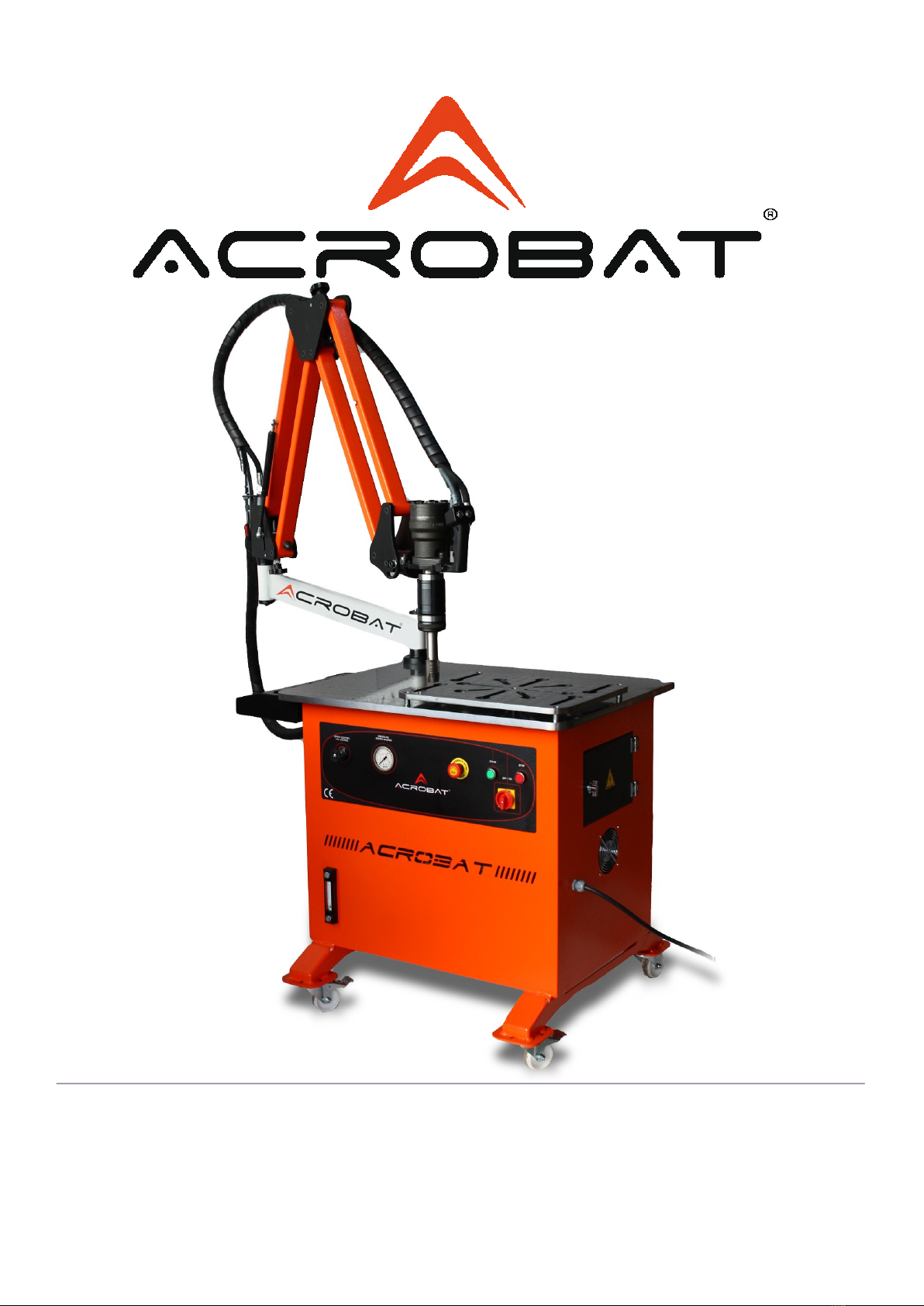
Hydro Motor
Hydraulic Hose
Handle
Ring
Front Paralel Arm
Piston Adjustment Handle
Piston
Piston
Adjustment
Handle
Level and
Heat
İndicator
Wheel
Dimmer
Pressure
indicator
Ventilation fan
Electric
panel
Start /
Stop
Pacco
Switch

3
CONTENTS
1- Safety Rules - - - - - - - - - - - - - - - - - - - - - - - - - - - - - Page 4- 5 –6
2 - Machine’s Usage - - - - - - - - - - - - - - - - - - - - - - - - - - Page 7
3 - Technical Properties - - - - - - - - - - - - - - - - - - - - - - - - Page 7
4 - Standard Accessories - - - - - - - - - - - - - - - - - - - - - - - Page 7
5 - Optional Accessories - - - - - - - - - - - - - - - - - - - - - Page 7
6 - Machine’s Assmebly - - - - - - - - - - - - - - - - - - - - - - - - Page 8
7 - Operation of Machine - - - - - - - - - - - - - - - - - - - - - - Page 9 - 10 - 11
8 - Maintenance of Machine - - - - - - - - - - - - - - - - - - - - - - - Page 12
8-1 - Filling Hydraulic Oil - - - - - - - - - - - - - - - - - - - Page 12
9 - Maintenance Control List - - - - - - - - - - - - - - - - - - - - - - - Page 13
10 - Safe Tap Holder System - - - - - - - - - - - - - - - - - -Page 13
11 - Control Circuit - - - - - - - - - - - - - - - - - - - - - - - -- - - Page 14
12 - Power Cycle - - - - - - - - - - - - - - - - - - - - - - - - - - - -- - - Page 15
13 - Drawing Diameters - - - - - - - - - - - - - - - - - - - - - - - -- -- - - Page 16
14 - Spindle—Part List - - - - - - - - - - - - - - - - - - - - - - - -- -- - - Page 17

4
1- Safety Rules
Your machine works at 380 V.
Machine will not work when phases are connected inverse, because there is phase protection relay at the
machine.
DEFINING SAFETY INFORMATION
Possible dangers may be prevented by reading explanations carefully. Keep people (especially children)
away from working eld during tapping process, except for the operator.
UNDERSTANDING SAFETY WARNINGS
Read manual carefully.
Use your machine at a suitable working environment. Unsuitable modications will aect safe operation
and long life of your machine negatively.
HAVE ELECTRIC INSTALLATION CONNECTED BY A COMPETENT ELECTRICIAN
Do not work the machine before putting oil into machine's hydraulic unit. Make sure hydraulic hose ttings
are rmly tightened.
WARNING! THERE IS HIGH PRESSURE IN THE MACHINE
PRESSURED OIL MAY HARM YOUR BODY
Metal parts may jump out when tapping. To prevent injuries arising from this reason, you have to wear
protective eye glasses for job, with edge protection
SPREADING METAL PARTS MAY HARM YOUR EYES
Heat will occur because of tap's friction to material. Do not touch hot parts with bare hands.
HOT PARTS MAY CAUSE BURNS

5
1- Safety Rules
Placing any part of the body on the machine while the machine is turned on is prohibited. It is also
prohibited to place on the machine or near the machine materials that are not mounted on the machine for
processing. These materials may be under the inuence of a working machine vibrations and cause a threat
to the health of people in the vicinity.
It is forbidden to operate the machine by people who are not familiar with the manual.
The user is required to secure the area around the machine to protect bystanders from being hit by a
moving part of a machine or workpiece`s splinter.
The machine must be operated by no more than one person (the operator) at a time.
Operate wearing clothes with narrow buttoned cus.
Long hair should be tied up.
If you notice irregularities in the operation of the machine immediately stop the operation and contact your
service representative.
It is forbidden to operate the machinery while intoxicated.
Children can not approach the machine.
When the machine is running, stay clear of the rotating tap
It is forbidden to leave the machine running unattended.
When the machine is running do not perform any operations in its surrounding area.
Never service the machine with motor on.
Never operate, service, repair or adjust machine without proper instruction from your supervisor and
without reading and understanding the instruction manual. It is the employer's responsibility to implement
the above instructions and to provide proper safety measures necessary for each particular use, operation,
setup or service of the machine.
Do not remove the labels from machine for any reason.
Heat will occur because of tap's friction to material. Do not touch hot parts with bare hands.
This is a very important chapter because in the past purchasers of ACROBAT tapping machines used it in a
manner that endangered the persons in the vicinity of the machine and the environment in which the
machine was located.
The machine is built mainly of steel and can not be used for combustible materials and harmful. The
customer must check whether the processed materials meet these requirements and do not pose a threat
to people living in the vicinity.
6
1- Safety Rules
C
AE
D
B
NOISE EMITED BY THE MACHINE
The device properties used to measurement.
Model : Delta Ohm HD2110
Serial Number : 14000044R
The measurement condition was made as below :
15 °C and % 55 Rh
Results of measuArement
A point 72,2 dB(A)
B point 72,5 dB(A)
C point 71,5 dB(A)
D point 70,5 dB(A)
E point 70,0 dB(A)

7
2– Machine’s Usage
Acrobat M36 Hydraulic tapping machine is designed to help you perform your tapping works easily,
quickly and economically. It provides you with fast tapping possibility thanks to special hydraulic system
with high torque.
Connection is vertical to ground thanks to its acrobatic arm, horizontal operation is possible if you desire.
Prevents the breakage of tap thanks to safe type tap holders, and provides savings for you.
3– Technical Properties
Working Pressure : 60 Bar - 120 Bar
Power : 5.5 kw
Speed: 0– 125
Machine Wight : 260 Kg
Reaching Capacity : 2050 mm
Elevation Capacity : 920 mm
Rotating Capacity : 360 degree
Table Height : 900 mm
Widht of Table : 700 mm
Lenght of Table : 900 mm
4– Standard Accessories
5– Optional Accessories
1– Angle head system
2– Connection bolts
3– Tap holder placement socket
4– Hydraulic system
1– Tap holders with or without safety
2– Fixed head system
3– Mobile table at any size

8
6– Machine Assembly
Place the base ange of machine in such a way to t table connection holes. Make sure you tighten bolts
after you place them with suitable Allen wrench.
WARNING! Make sure the connection surface of table is clean.
The smallest defect here (burr, small metal pieces) will prevent your machine to work vertically to ground.
After you place the bolts, remove package bands and uncover the machine.
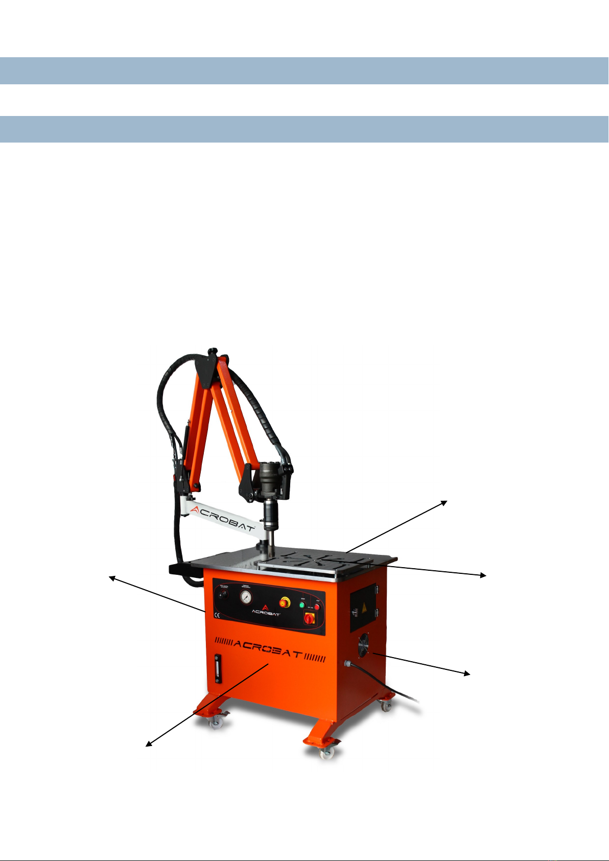
To make machine adjustment for 90 degrees (See Picture-1) loosen bolts with number 1 and number 2 as in
the picture (2 bolts facing each other). So that front head group will become free.
Press the mouth to which safe tap holder is connected,rmly on the surface you want to carry out tapping.
(PICTURE 4/ 90 degrees of leaning mouth) Tighten bolts with number 1 and number
2 again after surface leans. Make sure surface leaning does not change during the process of tightening
bolts. In that way 90 degrees adjustment of your machine will be done.
4
Picture –1
Hardness adjustment mechanism which allows lifting its weight is available on the acrobatic arm.
[See Picture 1) Front parallel arm group hardness adjustment can be done via handle with number 3 as
seen on the picture, and handle with number 4 is used for rear parallel arm group's hardness adjustment.

9
7– Operation Of Machine
Machine includes a 5.5 kw electric motor. Firstly measure the currents coming to plug you will use before
connecting your machine to plug and operating it. It must be 380 V between the phases and 220 V
between phase-neutral. If alternating current is reaching to system, it will damage electrical system of
your machine. In this situation, use a regulator to balance phases before operating the machine.
WARNING! Otherwise electric faults which may occur will not be in scope of guarantee.
Electric installation has phase protection relay. So that when phase with reverse order reaches to electric
motor, phase protection relay activates and prevents the reverse operation of electric motor and
hydraulic pump which is connected to motor from working in reverse direction, and protects the system.
(See Picture 2) In such a situation if the machine is not working, remove machine's three-phase electric
cable and connect to another suitable three-phase socket. When the phase coming to motor is correct,
system will activate.
To start the machine open pacco switch on unit and press on motor start button (green button) after
waiting for 5 seconds. (See Picture 3) And hydraulic system will become activate
MOTOR
STOP
MOTOR
START
PACCO
SWITCH
Picture –3
When the lamp is o
REVERSE PHASE
When the lamp is 0n
FLAT PHASE
Picture –2

10
7– Machine’s Operation
Button on handle at the end of acrobatic arm (See Picture 4) adjusts machine's spindle rotation direction.
Button stays at middle position automatically when machine is not used and spindle does not rotate. To be
able to turn spindle clockwise, press and hold the button to left. In that way spindle will rotate clockwise.
When you press and hold the button to right, spindle will rotate counter-clockwise.
Handle
Left Button
Attach the tap you want for tapping to tap holder with suitable metric according to your tap. If the tap
you will use is attached to a tap holder of dierent metric, your tap may break because of torque
disagreement. Place the teeth near tap holder in such a way to t teeth sockets at the end of module, by
pushing the ring on module at the end of spindle upwards, and release the ring; locking mechanism will
work automatically and x the tap holder. ( See Picture 4)To remove tap holder from its place, it will be
enough to lift ring on module upwards.
Bring the tap (which is suitable for the hole you drilled beforehand, or which you will tap) on the hole and
press slightly and provide mouthing (diameters of holes to be drilled according to taps for tapping can
be found at the end of guide).
Then by pressing button to left side, make spindle turn clockwise. This way tapping tool will begin
process of tapping for hole. When the process is done, by holding button pressed to the right, make the
spindle turn counter-
clockwise. In that way tap tool will come back from tapped hole. If you lubricate the tap with suitable
grease before contacting with the material it will increase cutting speed and extend the life of the tap.
Picture 4
Safe Tapping Holder
Ring
90 Degree
Damping Surface
Right Button
11
7– Machine’s Operation
Huk 2000 Rh (M5-M36) hydraulic tapping machine works at 100 rpm speed for tapping processes between
M5 and M36. İt is possible to adjust spindle cycle at speed adjustment dimmer, according to size of teeth
you will tap. You can use it at any speed by reducing cycle by using accurate speed adjustment dimmer
for bigger teeth; and increase cycles with accurate speed adjustment for smaller teeth. Huk 2000 Rh
Hydraulic tapping machine can carry out tapping horizontally.
When you want to carry out tapping (See Picture 6) slightly loosen bolts with number 1 and number 2 as
seen on the picture ( two bolts looking at each other). This way the front head will turn to horizon and
tapping head will be able to rotate 360 degreess.
Then only tighten bolts with number 2 and leave bolt with number 1 loose. Because head group needs to
be free during horizontal tapping process. It is to ensure that head and related tap move easily at the axis
of hole you drilled during horizontal tapping , and being able to adjust itself according to angle.
Your machine is ready for horizontal tapping proccess.
If you put tap holders whose job nished to the tap holder sockets at sides you can prevent possible
accidents.
When you job ends with the machine, press the motor stop (red button) button at the unit and close
pacco switch. Keep acrobatic arm at closed condition when you are not working with the machine.
Picture 5

12
8– Maintance of Machine
Fill oil tank in the table with minimum 90 lt, maximum 100 It with hydraulic oil (grade 46).
Periodically change hydraulic oil after 2500 hours of usage to use hydraulic motor and machine at desired
performance with long life.
Track oil level with indicator at certain periods. Clean the inside of safe tap holders with pressured air at
certain periods. Otherwise there may be breakage possibility for the taps.
Thin machine oil and grease shall be applied to suitable grease ttings at transmission unit at certain
periods depending on machine's operation frequency.
To change hydraulic oil, open blind plug at the bottom of machine and evacuate hydraulic oil. After
hydraulic oil is completely emptied, tighten blind plug again at its place.You can ll hydraulic oil (grade
46) with funnel (minimum 90 It, maximum 100 It) by opening storage cover.
8–1 Filling Hydraulic Oil
When you want to ll machine with hydraulic oil, you can ll hydraulic oil (grade 46) at minimum 90 It,
maximum 100 It with the help of funnel by opening storage cover as in the picture (See Picture-7).
STORAGE
COVER
Picture 7
13
9 – Maintenance Control List
Safe type tap holders are produced separately for each metric tooth and they have a torque-adjusted
system inside of them. This system is adjusted by producing company according to torque values which
prevent breakage of tap you use, and prevents being exposed to too much force. It reduces tap breakage
risk to minimum. If the hole you use for tapping is a blind hole and if tap reached to bottom or if tap cannot
move because of the jamming of burr created during tapping process or similar reasons, this torque-
adjusted safe tap holder will become activated and even if you continue working for tapping, the machine's
spindle will turn but will not rotate the tap and tap will not move. So that tap breakage risk will be reduced
to minimum. Also decay of tapped part and tap tool costs will be minimum.
According to variety of the tap you use and the hardness of part for which you are carrying out tapping,
torque values of tap holders can be adjusted manually. Torque hardness of safe tap holder can be
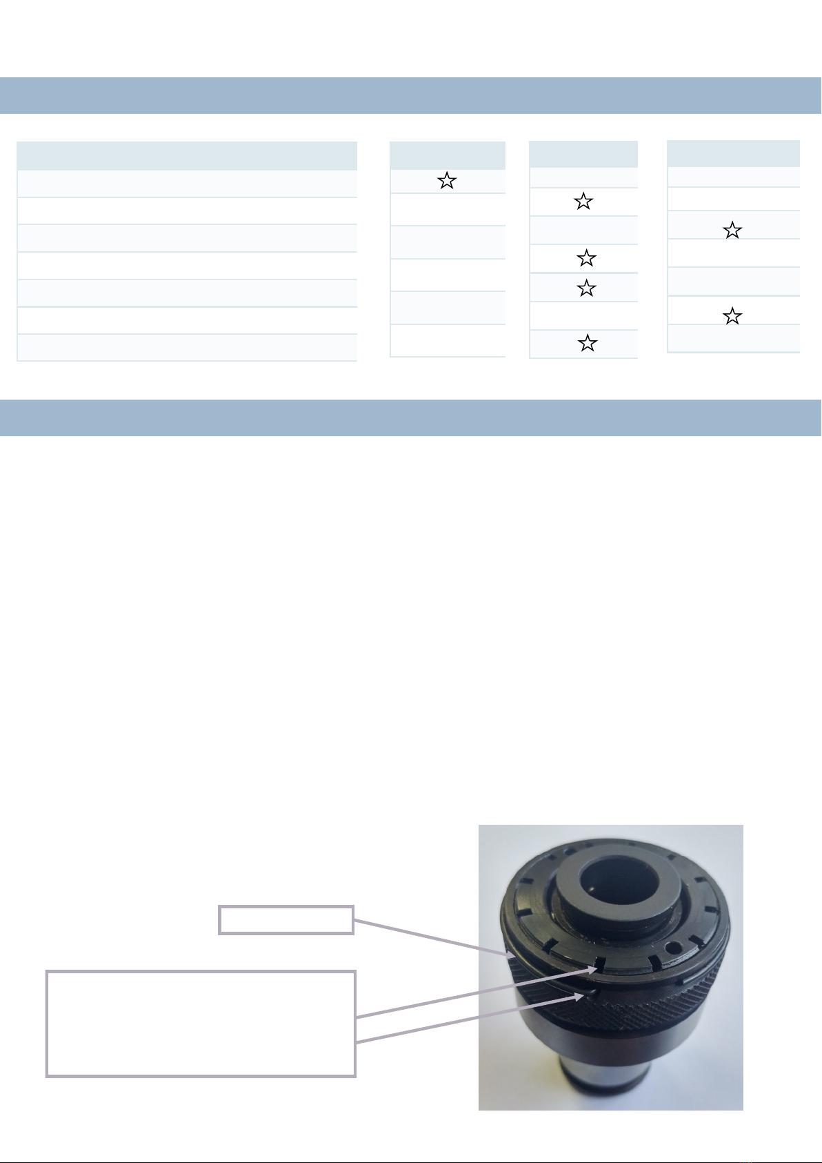
increased or reduced. If your tap breaks before tap holder is activated remove wire segment at the front
side of tap holder (See Picture 8) as seen in the picture, rotate interior hub of holder one grade in counter-
clockwise direction in such a way to t wire segment entrance holes on the hub, and place wire segment
again to its place. In that way torque value of your tap holder will be reduced and your tap will not break
with the activation of safe torque system before your tap
breaks. To operate safe torque system at later and higher torque values, apply the above mentioned
process by rotating clockwise. In that way torque value of tap will be increased and torque system will be
activated later.
WARNING! Attention must be paid at this process because the breakage risk of tap will increase as it will be
exposed to bigger force
10 - Safe Tap Holder System
CONTROL POINTS
HYDRAULIC OIL LEVEL CONTROL
HYDRAULIC OIL LEAKAGE CONTROL
HYDRAULIC OIL REPLACEMENT
GENERAL CLEANING
CONTROLLING CONNECTION BOLTS
CONTROLLING ELECTRIC CONNECTIONS
CLEANING TAP HOLDERS
15 DAY
MONTHLY
EVERY 2500 H
WIRE SEGMENT
THE SOCKET WHERE WIRE SEGMENT IS
PLACED AND CHANNEL SHOWN WITN
ARROW MUST COINCIDE WITH EACH
OTHER
Picture 8

14
11– Control Circuit

15
12– Power Cycle

16
13– Drawing Diameters
17
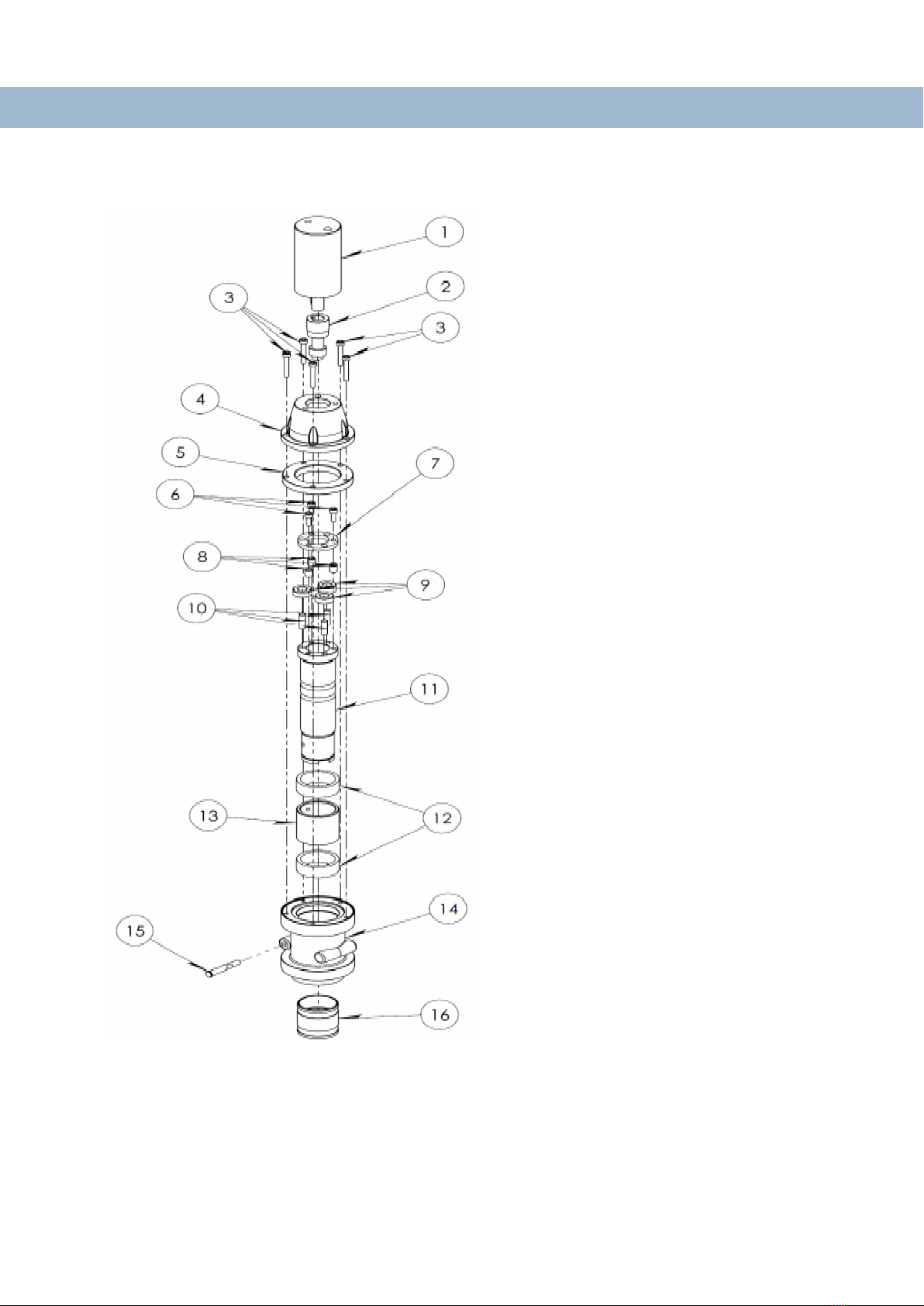
14– Spindle – Part List
1. HYDRAULIC MOTOR
2. PINION GEAR
3. M6 X 40 BOLT
4. HYDRAULIC MOTOR
FLANGE
5. OUT SUN GEAR
6. M6 X 25 BOLT
7. GEAR FLANGE
8. NEEDLE BEARING
9. PLANET GEAR
10. PLANET GEAR PIN
11. SPINDLE
12. SPINDLE BEARING
13. SPINDLE RING
14. SPINDLE MAIN BODY
15. SPINDLE LOCKING PIN
16.TAP COLLET LOCKING
RING
Other manuals for M5
1
This manual suits for next models
1
Table of contents
Other Acrobat Industrial Equipment manuals

Popular Industrial Equipment manuals by other brands

RINGSPANN
RINGSPANN FRS Series Installation, Lubrication, Maintenance Instructions

Pepperl+Fuchs
Pepperl+Fuchs PGV100RS-F200-B16-1,5M manual

Bühler technologies
Bühler technologies GAS 222.30 Assembly, installation and operation instructions

Yamaha
Yamaha SIGMA-G5SII Service information

ABB
ABB HT611632 Operation manual

evoheat
evoheat EVO Fusion-i Series manual


