Acrosser Technology AR-B1622 User manual

AR-B1622 User’s Guide
1
AR-B1622
AMD GX3 , VGA , LAN ,
PC104+ , 2 COM , 4 USB
User’ s Guide
Edition: 1.1

AR-B1622 User’s Guide
2
1. INTRODUCTION
Welcome to the AR-B1622 Single Board Computer. The AR-B1622 board Low power GX3 series Processors with
the advanced chipset CS5536. This product is designed for the system manufacturers, integrators, or VARs that
want to provide all the performance, reliability, and quality at a reasonable price.
In addition, the AR-B1622 provides on chip VGA. The VGA, which provides up to True Color (32 bit) 1024x768, or
High Color (16 bit) 1280x1024 resolution. The VGA memory is share main memory (2M, 4M, or 8M). AR-B1622
also has 24-bit LVDS function in the system.
The AR-B1622 is loaded with special on-board features that rival full-size systems. It has one network controller on
board, uses Realtek RTL8100BL LAN controller, a fully integrated 10/100BASE-TX solution with high performance
networking functions. Supports Compact Flash™ Type II interface. Plus optional support for AC97 sound with
CD-input. The AR-B1622 also includes one 200-pin SO-DIMM DDR sockets for up to 512 MB total on-board
memory. The AR-B1622 has two on-board serial ports; COM1, COM2 with RS232C, 4 USB ports, and tough
industrial grade construction. All these features make the AR-B1622 a very "system integrator friendly" solution,
perfect for handling applications in the harshest unmanned environments.
MEMORY BUS
CRT OUT
TO ETX
CON
ATA-66
LX Processor
Clock
LVDS
W83627
(SST FWH)
USB2.0
REFCLK
(CS5535/CS5536)
PRIMARY IDE
PCI(33/66 MHz)
South Bridge
LPC BUS
USB x 4
TFT
14.318 MHz
Crystal
Synthesizer
(MK1491-09F)
SODIMM200
DDR
10/100M
Ethernet
48 MHz
66 MHz
PCI BUS(33MHz or 66MHz)
CRT
(24Bit)
Flash
IDE
BIOS
KB/MS
COM1
AND
COM2
AR-B1622 System Block Diagram

AR-B1622 User’s Guide
3
SPECIFICATIONS
CPU: GX3
Chipset: CS5536
RAM memory: Supports DDR-RAM, on-board 200-pin SO-DIMM up to 1GB DDR-RAM memory module
Display Interface: CRT –10-pin pin-header.
LVDS – for 24 bit TFT LCD Panel.
Ultra ATA/33/66/100 IDE Interface:
Series ports: On-board two 2x5x2.00mm pin-header connector for COM1, COM2.
USB port: Four USB 2.0
Ethernet: On-board one RTL8100C, supports 10/100Mbps Base-T with 1x7 2.00mm pin-header.
K/B & Mouse: On-board PS/2 Keyboard and Mouse pin-header.
Power Req.: +5V 2A and +12V 1A maximum
PC Board: 8 layers, EMI considered
GPIO: 8pin TTL compatible
Dimensions: 3.775” x 3.555”(Standard Dimension for PCI104)
Operating Temperature: 0oC~ 60℃

AR-B1622 User’s Guide
4
2. SETTING UP SYSTEM
This chapter describes how to install the AR-B1622. At first, the layout of AR-B1622 is shown, and the unpacking
information that you should be careful is described.
Overview
System Settings
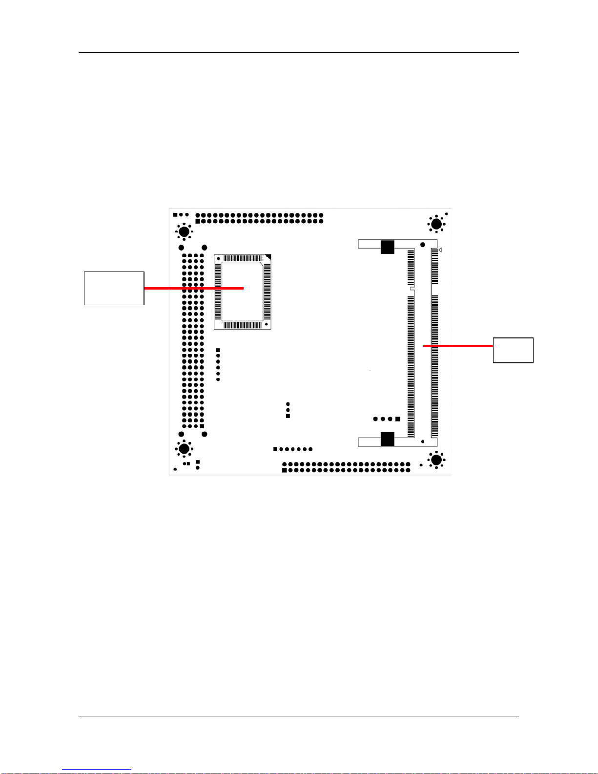
2.1 AR-B1622 OVERVIEW
TOP PLACEMENT
V_JP1
V
G
A1 DI
O
1
J5
BIOS
KBMS1
8100C
USB2 USB1
BT1 JP2
LCD1 COM1 COM2 JFRT1
CPU LX800
South Bridge CS5536
CN21
J4
IDE
J3
AR-B1622 User’s Guide
5
BOTTOM PLACEMENT
Super I/O
W83627
J1

AR-B1622 User’s Guide
6
2.2 SYSTEM SETTINGS
Jumper pins allow you to set specific system parameters. Set them by changing the pin location of the jumper
blocks. (A jumper block is a small plastic-encased conductor that slips over the pins.) To change a jumper
setting, remove the jumper from its current location with your fingers or small needle-nosed pliers. Place the
jumper over the two pins designated for the desired setting. Press the jumper evenly onto the pins. Be careful
not to bend the pins.
We will show the locations of the AR-B1622 jumper pins, and the factory-default settings.
CAUTION: Do not touch any electronic components unless you are safely grounded. Wear a
grounded wrist strap or touch an exposed metal part of the system unit chassis. The static discharges
from your fingers can permanently damage electronic components.
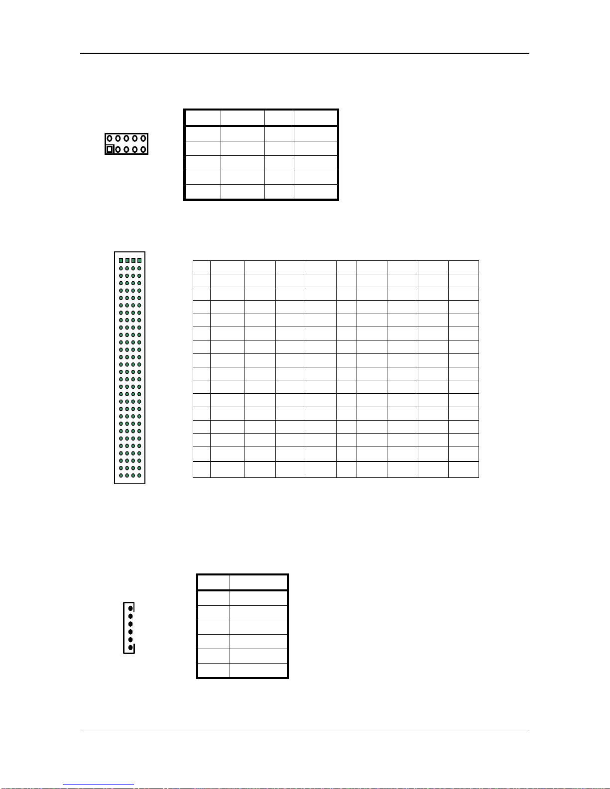
2.2.1 LCD1 (LCD CONNECTOR)
PIN
DEFINE
PIN
DEFINE
PIN
DEFINE
PIN
DEFINE
1 GND 2 FPCLK 23 D14 24 D15
3 GND 4 HSYNC 25 D16 26 D17
5 VSYNC 6 GND 27 GND 28 D18
7 D0 8 D1 29 D19 30 D20
9 D2 10 D3 31 D21 32 D22
11 D4 12 D5 33 D23 34 GND
13 GND 14 D6 35 LCDVDD 36 LCDVDD
15 D7 16 D8 37 12V 38 12V
17 D9 18 D10 39 GND 40 GND
19 D11 20 GND 41 DE 42 LVDS_BKLTEN
21 D12 22 D13 43 GND 44 ENVDD
2 1
44 43

AR-B1622 User’s Guide
7
2.2.2 VJP1 (LCD 3V or 5V)
2.2.3 COM1&COM2
2.2.4 JFRT1
2.2.4 VGA1
PIN DEFINE
1-2 3V
2-3 5V
PIN DEFINE PIN
DEFINE
1 -DCD 2 -DSR
3 SIN 4 -RTS
5 SOUT 6 -CTS
7 -DTR 8 -RI
9 GND 10 GND
PIN DEFINE
1-2 RESET
3-4 PIN 3:5V(PWR LED)
PIN 4:GND
5-6 PIN 5:5V
PIN 6:HD LED
7-8 PIN 7:SPEAKER+
PIN 8:SPEAKER-
9-10 NC
PIN DEFINE
PIN
DEFINE
1 RED 2 GND
3 GREEN 4 GND
5 BLUE 6 GND
7 V-SYNC 8 SSCL
9 H-SYNC 10 SSDA
1
3
2
1
10
9
2
1
10
9
2
1
10
9
AR-B1622 User’s Guide
8
2.2.5 DIO1(GPIO)
2.2.6 J5(PCI104)
2.2.7 KBMS1
PIN DEFINE
PIN
DEFINE
1 GND 2 5V
3 BIT 4 4
BIT 5
5 BIT 5 6
BIT 6
7 BIT 0 8 BIT 1
9 BIT 2 10 BIT 3
A B C D A B C D
1 NC SERIR +5V AD0 16 AD21 AD20 GND AD19
2 NC AD2 AD1 +5V 17 +3.3V AD23 AD22 +3.3V
3 AD5 GND AD4 AD3 18 IDSEL0 GND IDSEL1 AD22
4 C/BE0# D7 GND AD6 19 AD24 C/BE3# NC AD23
5 GND AD9 D8 GND 20 GND AD26 AD25 GND
6 AD11 NC AD10 NC 21 AD29 +5V AD28 AD27
7 AD14 D13 GND AD12 22 +5V AD30 GND AD31
8 +3.3V C/BE1# AD15 +3.3V 23 REQ0# GND REQ1# NC
9 SERR# GND PULL PAR 24 GND REQ2# +5V GNT0#
10 GND PERR# +3.3V PULL 25 GNT1# NC GNT2# GND
11 STOP# +3.3V LOCK# GND 26 +5V CLK GND CLK
12 +3.3V RDY# GND DEVSE 27 CLK +5V NC GND
13 FRAME# GND IRDY# +3.3V 28 GND INTD# +5V PCIRST
14 GND AD16 +3.3V C/BE2# 29 +12V INTA# INTB# INTC#
15 AD18 +3.3V AD17 GND 30 NC NC NC NC
PIN DEFINE
1 MSDATA
2 KBDATA
3 GND
4 5V
5 MSCLK
6 KBCLK
2
1
10
9
1
6

AR-B1622 User’s Guide
9
2.2.8 USB1&USB2
2.2.9 BT1
2.2.10 JP2(SERIRQ)
2.2.11 J4(LAN)
PIN DEFINE
PIN
DEFINE
1 5V 2 5V
3 DATA- 4 DATA-
5 DATA+ 6 DATA+
7 GND 8 GND
9 GND 10 GND
PIN DEFINE
1 V+(3.3V)
2 GND
PIN DEFINE
close Connect SERIQR to PCI104 pin B1
open Disconnect SERIRQ
PIN
DEFINE
1 TX+
2 TX-
3 RX+
4 RX-
5 GND
6 CONNECT RC CIRCUIT TO GROUND
7 CONNECT RC CIRCUIT TO GROUND
2
1
10
9
2 1
1 7
AR-B1622 User’s Guide
10
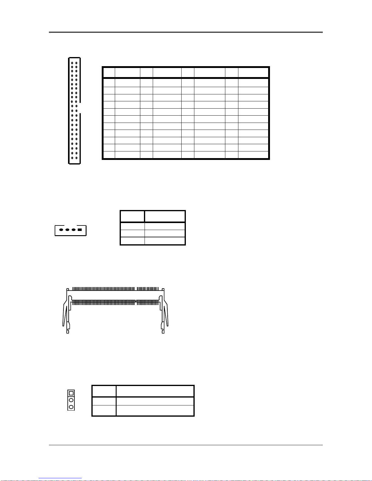
2.2.12 IDE1
2.2.13 CN2(Power)
2.2.14 J1(DDR-SODIMM)
2.2.15 J3(V-BAT & CMOS Clear)
PIN DEFINE PIN DEFINE PIN DEFINE PIN DEFINE
1 RESET# 2 GND 23 IOW# 24 GND
3 DATA7 4 DATA8 25 IOR# 26 GND
5 DATA6 6 DATA9 27 NC 28 BALE
7 DATA5 8 DATA10 29 NC 30 GND
9 DATA4 10 DATA11 31 INTERRUPT 32 IOCS16#
11 DATA3 12 DATA12 33 SA1 34 NC
13 DATA2 14 DATA13 35 SA0 36 SA2
15 DATA1 16 DATA14 37 CS0# 38 CS1#
17 DATA0 18 DATA15 39 ACTIVE# 40 GND
19 GND 20 NC 41 5V LOGIC 42 +5V MOTOR
21 NC 22 GND 43 GND 44 TYPE
PIN DEFINE
1 12V
2-3 GND
4 5V
PIN DEFINE
1-2 Supply power for V-BAT
2-3 Clear CMOS
43
1
44
2
4 1
1
3
AR-B1622 User’s Guide
11
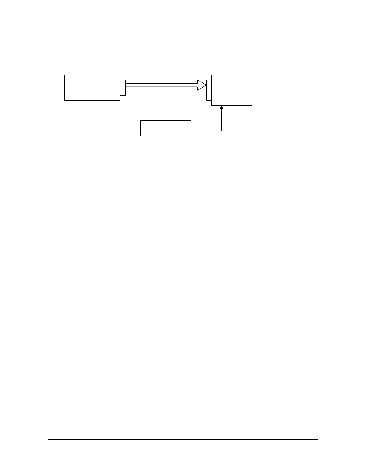
3. LCD FLAT PANEL DISPLAY
This chapter describes the configuration and installation procedures for LCD displays.
LCD Panel Block Diagram
Please visit our web site or contact with our technical support department for supports of LCD connecting.
TFT LCD Interface
AR-B1622 LCD
Panel
Inverter
Backlight
Power
AR-B1622 User’s Guide
12
4. BIOS CONSOLE
This chapter describes the AR-B1622 BIOS menu displays and explains how to perform common tasks needed to
get up and running, and presents detailed explanations of the elements found in each of the BIOS menus. The
following topics are covered:
zBIOS Setup Overview
zAdvanced CMOS Setup
zPeripheral Setup
zBoot
zBIOS Exit
4.1 BIOS SETUP OVERVIEW
The BIOS is a program used to initialize and set up the I/O system of the computer, which includes the
ISA bus and connected devices such as the video display, diskette drive, and the keyboard.
The BIOS provides a menu-based interface to the console subsystem. The console subsystem
contains special software, called firmware that interacts directly with the hardware components and
facilitates interaction between the system hardware and the operating system.
The BIOS default values ensure that the system will function at its normal capability. In the worst
situation the user may have corrupted the original settings set by the manufacturer.
After the computer is turned on, the BIOS will perform diagnostics on the system and display the size of
the memory that is being tested. Press the [Del] key to enter the BIOS Setup program, and then the
main menu will show on the screen.
The BIOS Setup main menu includes some options. Use the [Up/Down] arrow key to highlight the
option that you wish to modify, and then press the [Enter] key to select the option and configure the
functions.
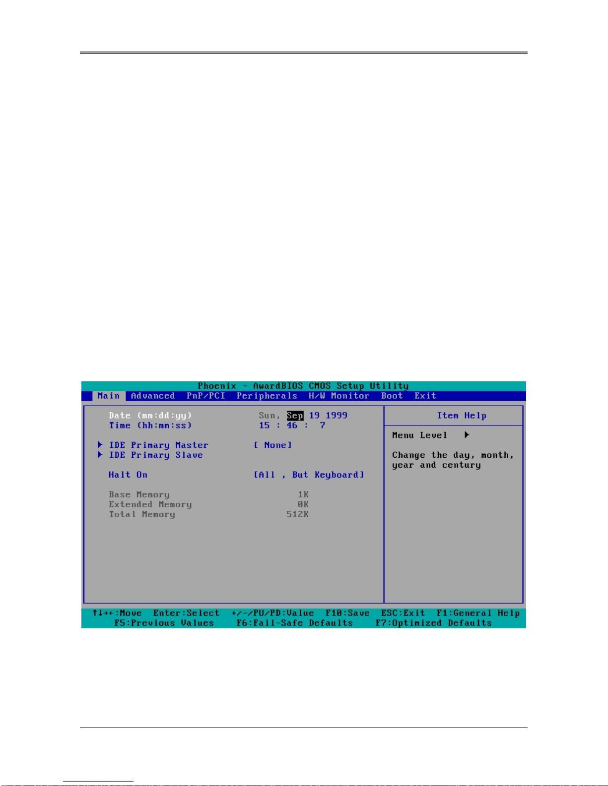
Setup Main Menu
The <Main> option allows you to record some basic system hardware configuration and set the system clock
and error handling. If the CPU board is already installed in a working system, you will not need to select this
option anymore.
AR-B1622 User’s Guide
13
Date & Time Setup
Highlight the <Date> field and then press the [Page Up] /[Page Down] or [+]/[-] keys to set the current
date. Follow the month, day and year format.
Highlight the <Time> field and then press the [Page Up] /[Page Down] or [+]/[-] keys to set the current
date. Follow the hour, minute and second format.
Hard Disk Setup
The BIOS supports 2 types for user settings, The BIOS supports <Pri Master> and <Pri Slave>, <Sec
Master> and <Sec Slave> so the user can install up to two hard disks.
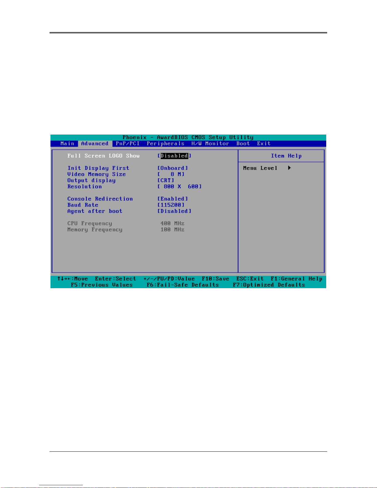
4.2 ADVANCED
Standard CMOS Setup
Full Screen Logo Show [Disable]
This allows you to enable or disable the full screen logo display feature.
Configuration options: [Disabled] [Enabled]
INIT Display First [Onboard]
Initialize the onboard video display before initializing any other display device on the system.
Thus the onboard display becomes the primary display.
Configuration options: [Disabled] [Enabled]
Video Memory Size [8M]
Configuration options: [None] [8M] [16M] [32M] [64M] [128M] [254M]
Output Display [CRT]
This allows you to choose output for your system display.
Configuration options: [CRT] [Flat Panel] [Panel +CRT]
Resolution [800x600]
This allows you to choose the display resolution.
AR-B1622 User’s Guide
14
Console Redirection
【
Enable
】
This allows you to enable the console function or not.
Baud Rate
【
115200
】
This allows you to set up the transfer speed for console.
Agent after boot
【
Disabled
】
This allows you to open the Agent after boot function or not.
4.3 POWER
Power Management [ACPI]
This allows you to enable or disable the ACPI function Configuration options: [Disabled] [ACPI]

AR-B1622 User’s Guide
15
4.3 PERIPHERALS
Peripherals
Onboard Serial Port 1 [3F8/IRQ4]
Choose serial port 1 I/O address. Do not set port 1, 2, 3 and 4 to the same address except for Disabled or Auto.
Onboard Serial Port 2 [2F8/irq3]
Choose serial port 2 I/O address. Do not set port 1, 2, 3 and 4 to the same address except for Disabled or Auto.
USB 1.0/1.1 Controller [Enables]
This should be enabled if your system has a USB installed on the system board and you want to use it. Even when so
equipped, if you add a higher performance controller, you will need to disable this feature.
USB 2.0 Controller [Enables]
This should be enabled if your system has a USB installed on the system board and you want to use it. Even when so
equipped, if you add a higher performance controller, you will need to disable this feature.
Onchip IDE Device
This enter this option you can enable or disable your IDE channel and set PIO mode or UDMA mode.
AR-B1622 User’s Guide
16
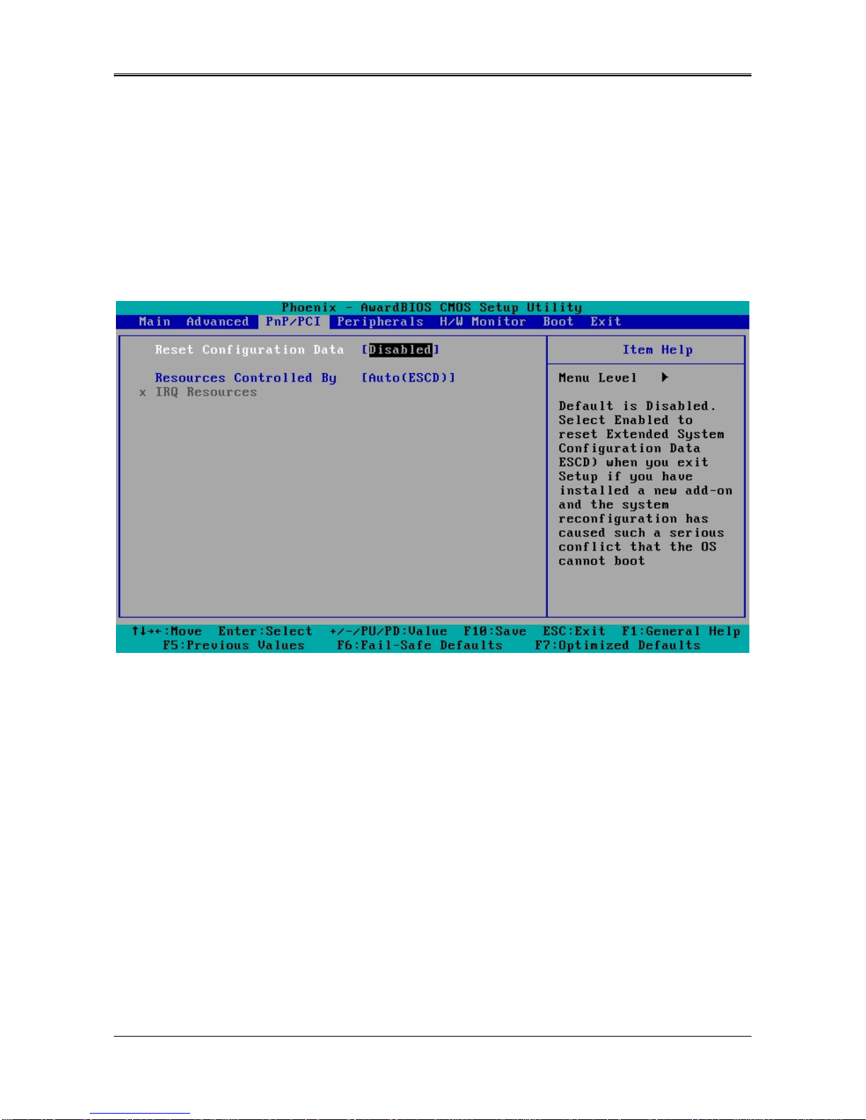
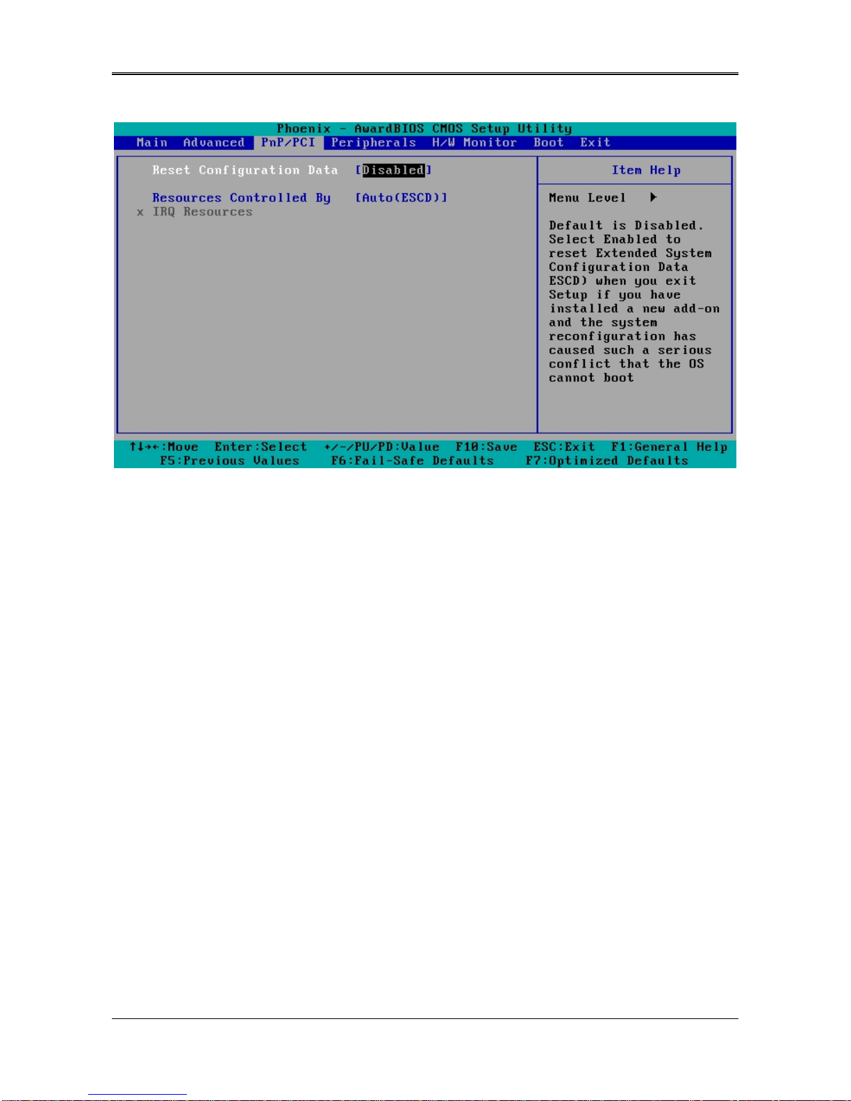
4.4PnP/PCI
PnP/PCI
Reset Configuration Data [Disable]
Normally, you leave this field Disabled. Select Enabled to reset Extended System Configuration Data (ESCD) when you
exit Setup if you have installed a new add-on and the system reconfiguration has caused such a serious conflict that the
operating system cannot boot.
Resources Controlled By [Auto (ESCD)]
This field sets control over the IRQ resources by the automatic (ESCD) system or manual assignment of IRQ
channels. The default enables automatic (ESCD) control. Configuration options: [Auto (ESCD)] [Manual].
AR-B1622 User’s Guide
17
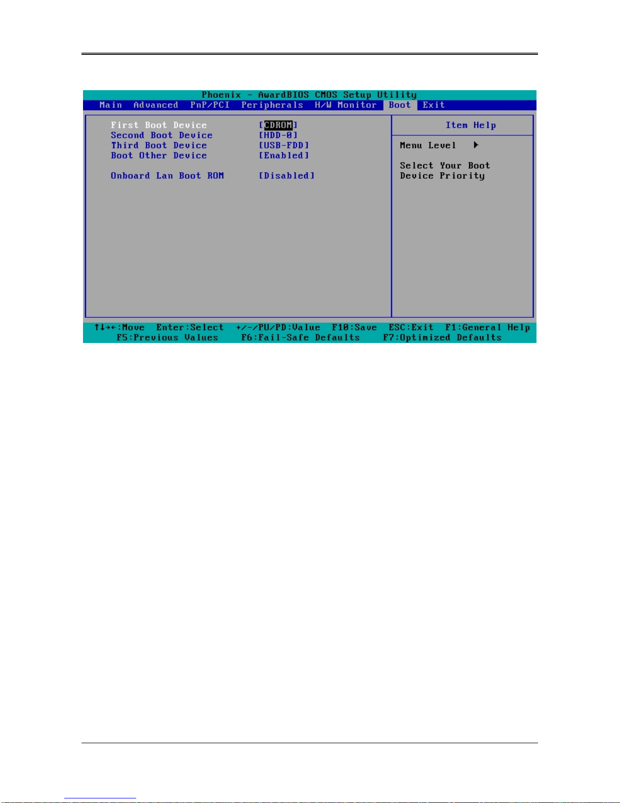
4.5 BOOT
BOOT
First/Second/Third Boot Device
HDD-0
SCSI
CDROM
HDD-1
USB-FDD
USB-ZIP
USB-CDROM
USB-HDD
LAN
Disabled
Boot Other Device [Enabled]
Configuration options: [Enabled] [Disabled].
LAN Boot Select [Disabled]
This allows you to enable or disable the LAN Boot function..
AR-B1622 User’s Guide
18
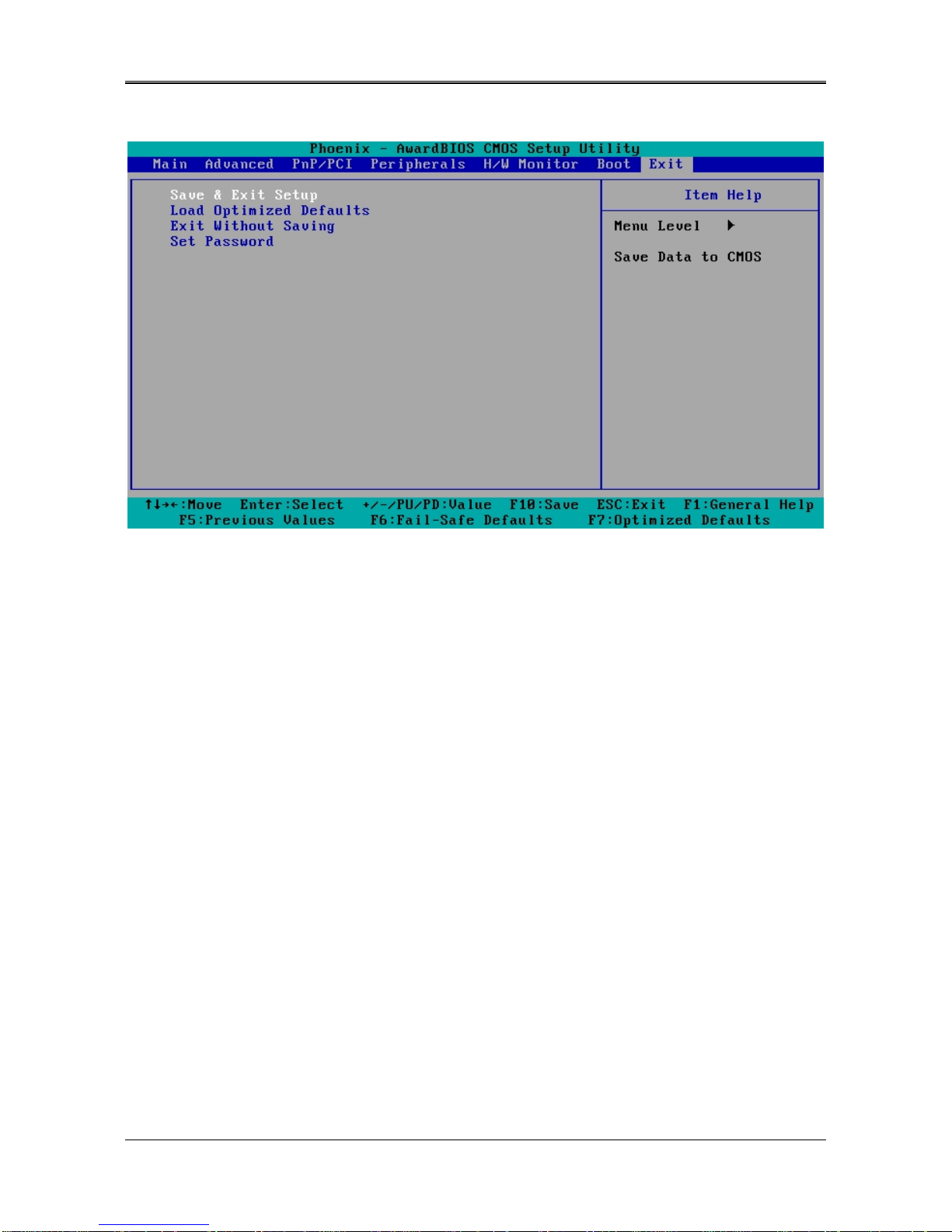
4.6 BIOS EXIT
Exit
When you have made all of your selections from the various menus in the Setup program, save your
changes and exit Setup. Select Exit from the menu bar to display the following menu.
Save & Exit Setup
Type “Y” will quit the Setup Utility and save the user setup value to RTC CMOS. Type “N” will return to Setup Utility.
.
Load Optimized Defaults
Selecting this field loads the factory defaults for BIOS and Chipset Features,
which the System automatically detects.
Exit Without Saving
Type “Y” will quit the Setup Utility without saving to RTC CMOS.
Type “N” will return to Setup Utility.
Set Password
This allows you to set a password for enter BIOS menu.

AR-B1622 User’s Guide
19
5. I/O address、IRQ and Memory Mapping
5.1 I/O address Mapping
AR-B1622 User’s Guide
20
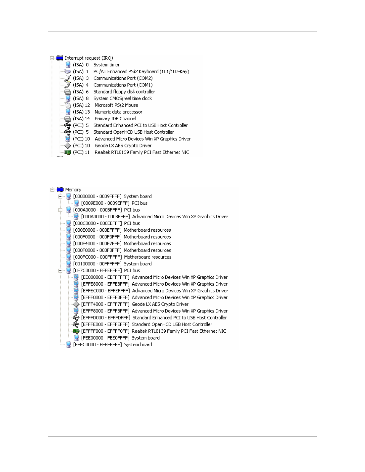
5.2 IRQ Mapping
5.3 Memory Mapping
Other manuals for AR-B1622
2
Table of contents
Other Acrosser Technology Desktop manuals

Acrosser Technology
Acrosser Technology AR-ES5432FL User manual

Acrosser Technology
Acrosser Technology AIV-TGH7E Series User manual

Acrosser Technology
Acrosser Technology AR-ES6050FLD Parts list manual

Acrosser Technology
Acrosser Technology AND-DNV3N2FL User manual

Acrosser Technology
Acrosser Technology AR-ES0892FL User manual

Acrosser Technology
Acrosser Technology AND-APL1N1FL Series User manual

Acrosser Technology
Acrosser Technology AR-B5630 User manual

Acrosser Technology
Acrosser Technology AR-R8601 User manual


