Acrosser Technology AR-B3001 User manual

ACROSSER TECHNOLOGY 1
CHAPTER 1 INTRODUCTION
1.1 GENERAL DESCRIPTION
The AR-B3001 is a low cost, high accuracy, low noise,
low drift A/D interface boards for the IBM PC/XT/AT and
their compatibles. It is half-length boards that install
internally in an expansion slot of an IBM Personal
Computer to turn the computer into an inexpensive, high-
precisioninstrumentfortemperature,humidity,pressure,
flow and level etc.. The AR-B3001 is constructed with a
12-bit (plus polarity bit) dual-slop integrating A/D
converter. It can be operated with 16 single-ended or 8
differential analog inputs. The analog input range of AR-
B3001 is -5V to +5V.
A complete software utility containing demo programs,
Assembly, Basica, and C drivers are furnished with the
board to minimize user's effort on application software
development. All the driver routines are provided with
source programs and can be modified to suit your
applications.
Block diagram of AR-B3001 is shown in figure 1-1.
All manuals and user guides at all-guides.com

ACROSSER TECHNOLOGY
2
Figure 1-1 AR-B3001 Functional Block Diagram
1.2 FEATURES
Inexpensive, half-size analog input board for IBM
PC/XT/AT and their compatibles.
16 single-ended or 8 differential inputs.
Maximum throughput 30 Hz.
Resolution : 12-bit and a sign bit.
+5V to -5V input range.
Assembly, C, and Basica drivers included.
Easy to use.
All manuals and user guides at all-guides.com
ACROSSER TECHNOLOGY 3
1.3 ORDERING INFORMATION
Followings list and describe part number of the AR-
B3001 board and its accessories.
Part Number Description
AR-B3001 16 channel analog input card
with user’s manual
AR-B9006 34-pin screw terminal board for
AR-B3001 with 0.6m flat cable
All manuals and user guides at all-guides.com

ACROSSER TECHNOLOGY
4
This page is intentionally left blank
All manuals and user guides at all-guides.com

ACROSSER TECHNOLOGY 5
CHAPTER 2 INSTALLATION
This chapter provides instructions for installing the AR-
B3001 in an IBM PC/XT/AT and compatibles.
2.1 SWITCHE, JUMPER AND CONNECTOR
There is one DIP switch and one jumper on the AR-
B3001. This section describes functional use of the
switch and jumper. It also provides a description of the
input connector. Figure 2-1 shows the location of each
switch, jumper, and connector for AR-B3001. Table 2-1
list the functions of jumper, switch, variable resistors and
connector shown in Figure 2-1.
Legend Description
DIP SW I/O Port Base Address
JP1 Differential/Single-Ended Selection
JP7 Reserved
VR1 Fine Adjustment of Full-Scale
VR2 Rugged Adjustment of Full-Scale
VR3 Reserved
VR4 Offset Adjustment
VR5 Common Mode Rejection Ratio Adjustment
J2 Input Connector
Table 2-1
All manuals and user guides at all-guides.com

ACROSSER TECHNOLOGY
6
Figure 2-1 Board Layout of AR-B3001
All manuals and user guides at all-guides.com

ACROSSER TECHNOLOGY 7
2.1.1 Base Address Settings
There is one DIP switch located on the AR-B3001 card.
It is used to select the base port address of the AR-
B3001. The operation of AR-B3001 is controlled through
the I/O ports. Four consecutive I/O ports are used by AR-
B3001. The base address of these I/O ports is selected
by using base address switch DIP SW. The AR-B3001 is
factory-configured for a base address of 3e0 Hex. If this
base address is already occupied, you will need to
change the base address switch setting. It is essential
that each peripheral device, such as an AR-B3001, be
assigned a unique base address within the range of 200
to 3fc Hex and that the address is on a 4-byte boundary.
Figure 2-2 shows the base address switch.
ON
12345678
DIP SW
A2 A3 A4 A5 A6 A7 A8 A9
Figure 2-2. Base Address Switch
All manuals and user guides at all-guides.com

ACROSSER TECHNOLOGY
8
Use the following table to select an AR-B3001 base port
address.
DIP SW ADDRESS ADDRESS VALUE
LINE Hex. Dec.
Switch 1 A2 4 4
Switch 2 A3 8 8
Switch 3 A4 10 16
Switch 4 A5 20 32
Switch 5 A6 40 64
Switch 6 A7 80 128
Switch 7 A8 100 256
Switch 8 A9 200 512
Address = 200*A9 + 100*A8 + 80*A7 + 40*A6 + 20*A5
+ 10*A4 + 8*A3 + 4*A2 (Hex)
-or-
Address = 512*A9 + 256*A8 + 128*A7 + 64*A6 + 32*A5
+ 16*A4 + 8*A3 + 4*A2 (Dec)
A9....A2 = 0 If switch is ON.
A9....A2 = 1 If switch is OFF.
Note: Setting the switch to the "ON" position indicates a
logical "0" and setting the switch to the "OFF"
position indicates a logical "1".
All manuals and user guides at all-guides.com

ACROSSER TECHNOLOGY 9
Use the following table as an aid for selecting an
unoccupied address.
HEX RANGE DEVICE
00-FF Reserved For System
170-178 Fixed Disk 1
1F0-1F8 Fixed Disk 0
201 Game Port
208-20A EMS Register 0
218-21A EMS Register 1
278-27F Parallel Printer Port 3 (LTP3)
2E8-2EF Serial Port 4 (COM4)
2F8-2FF Serial Port 2 (COM2)
300-31F Prototype Card/Streaming Type Adapter
378-37F Parallel Printer Port 2 (LTP 2)
380-38F SDLC, Bisynchronous 2
3A0-3AF Bisynchronous 1
3B0-3BF Monochrome Display and Parallel Printer
Port 1 (LPT1)
3C0-3CF EGA/VGA Adapter
3D0-3DF Color/Graphics Monitor Adapter
3E8-3EF Serial Port 3 (COM3)
3F0-3F7 Diskette Controller
3F8 3FF
S i l P t 1 (COM1)
Table 2-2. IBM PC I/O Address Map
All manuals and user guides at all-guides.com

ACROSSER TECHNOLOGY
10
2.1.2 Channel Configuration Jumper
The JP1 is used to select whether 16 single-ended or 8
differential analog input channels are to be used. To
select eight differential input channels, move the jumpers
to the right side. Likewise, to select 16 single-ended
analog input channels, move the jumpers to the left side
as shows in Figure 2-3.
JP1
Differential
JP1
1
Single-ended
(Factory preset)
1
Figure 2-3 Channel Configuration Jumper
All manuals and user guides at all-guides.com
ACROSSER TECHNOLOGY 11
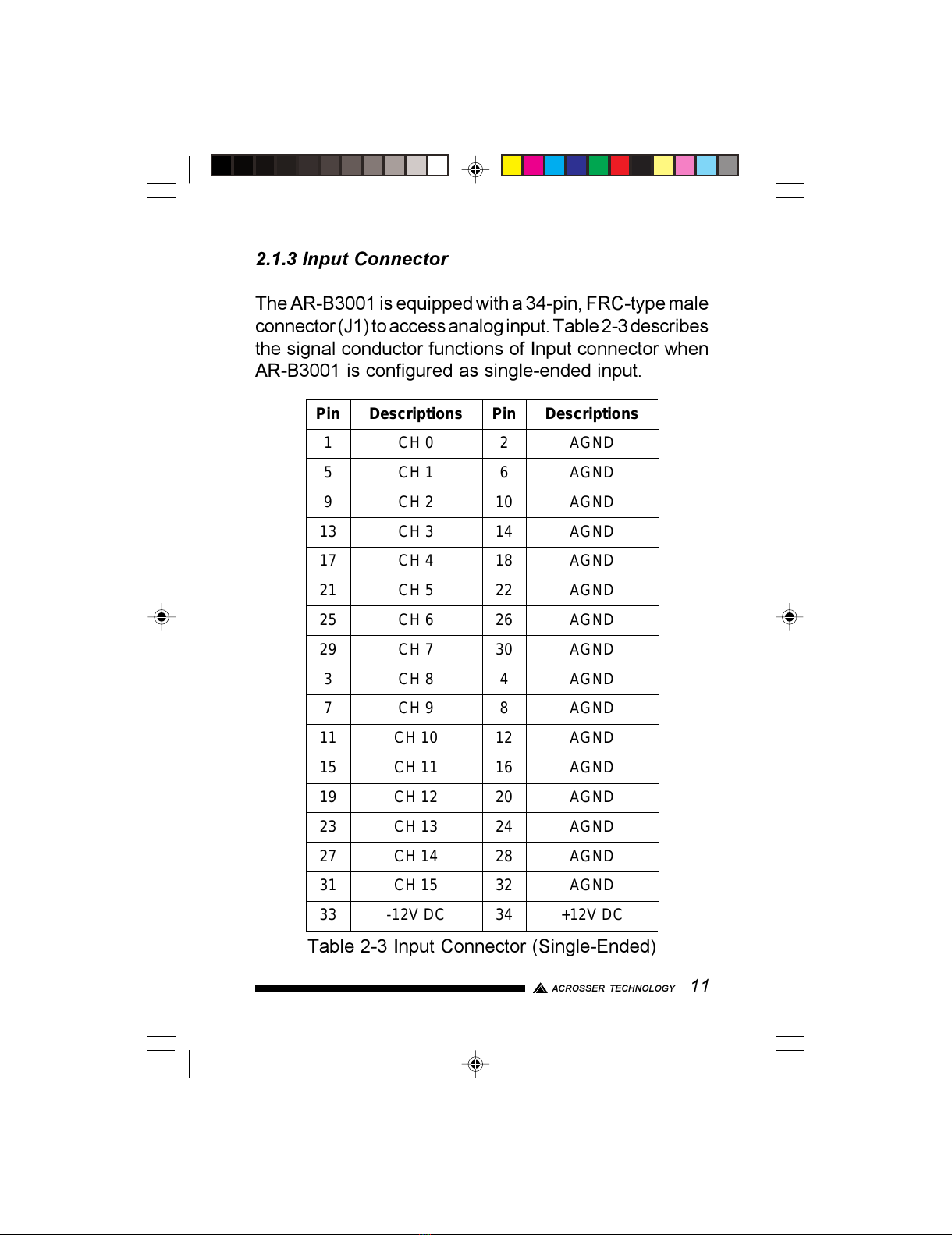
2.1.3 Input Connector
The AR-B3001 is equipped with a 34-pin, FRC-type male
connector(J1)toaccessanalog input.Table2-3 describes
the signal conductor functions of Input connector when
AR-B3001 is configured as single-ended input.
Pin Descriptions Pin Descriptions
1 CH 0 2 AGND
5 CH 1 6 AGND
9 CH 2 10 AGND
13 CH 3 14 AGND
17 CH 4 18 AGND
21 CH 5 22 AGND
25 CH 6 26 AGND
29 CH 7 30 AGND
3 CH 8 4 AGND
7 CH 9 8 AGND
11 CH 10 12 AGND
15 CH 11 16 AGND
19 CH 12 20 AGND
23 CH 13 24 AGND
27 CH 14 28 AGND
31 CH 15 32 AGND
33 -12V DC 34 +12V DC
Table 2-3 Input Connector (Single-Ended)
All manuals and user guides at all-guides.com
ACROSSER TECHNOLOGY
12
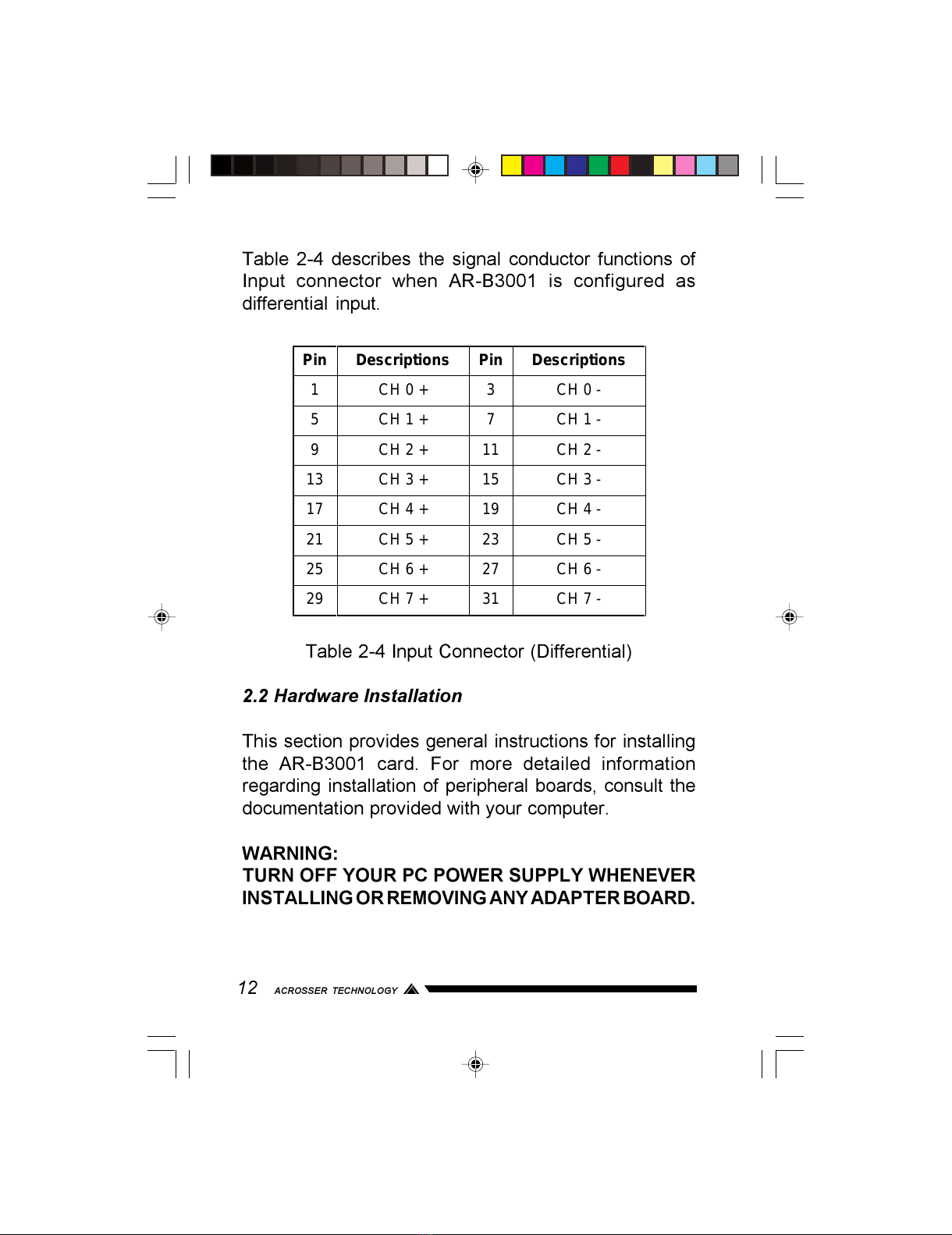
Table 2-4 describes the signal conductor functions of
Input connector when AR-B3001 is configured as
differential input.
Pin Descriptions Pin Descriptions
1 CH 0 + 3 CH 0 -
5 CH 1 + 7 CH 1 -
9 CH 2 + 11 CH 2 -
13 CH 3 + 15 CH 3 -
17 CH 4 + 19 CH 4 -
21 CH 5 + 23 CH 5 -
25 CH 6 + 27 CH 6 -
29 CH 7 + 31 CH 7 -
Table 2-4 Input Connector (Differential)
2.2 Hardware Installation
This section provides general instructions for installing
the AR-B3001 card. For more detailed information
regarding installation of peripheral boards, consult the
documentation provided with your computer.
WARNING:
TURN OFF YOUR PC POWER SUPPLY WHENEVER
INSTALLING OR REMOVING ANY ADAPTER BOARD.
All manuals and user guides at all-guides.com

ACROSSER TECHNOLOGY 13
Install the AR-B3001 card into your computer:
1. Set the switch and jumper as described in section 2.1.
2. Turn off the power of the computer and any peripheral
devices.
3. Unplug the power cord from the electrical outlet. Make
a note concerning location of all the cables and cords
attached to the rear of the system unit and then
disconnect.
4. Remove the system unit cover (refer to your computer
user's guide if necessary).
5. Choose an available option slot. Remove the screw
that secures the expansion slot cover to the system
unit.
6. Hold the AR-B3001 in one hand. With the other hand,
touch any metallic part of the computer's cabinet. This
will safely discharge any static electricity that has
build up in your body.
7. Align the gold edge connector with the edge socket
and install the back adapter with the adapter plate
screw. Gently press the board downward into the
socket. Re-install the adapter plate screw.
8. Replace the system unit cover.
9. Connect all cables and cords you previously removed
in step 3.
All manuals and user guides at all-guides.com

ACROSSER TECHNOLOGY
14
This page is intentionally left blank
All manuals and user guides at all-guides.com
ACROSSER TECHNOLOGY 15
CHAPTER 3 REGISTERS AND PROGRAMMING
3.1 REGISTERS
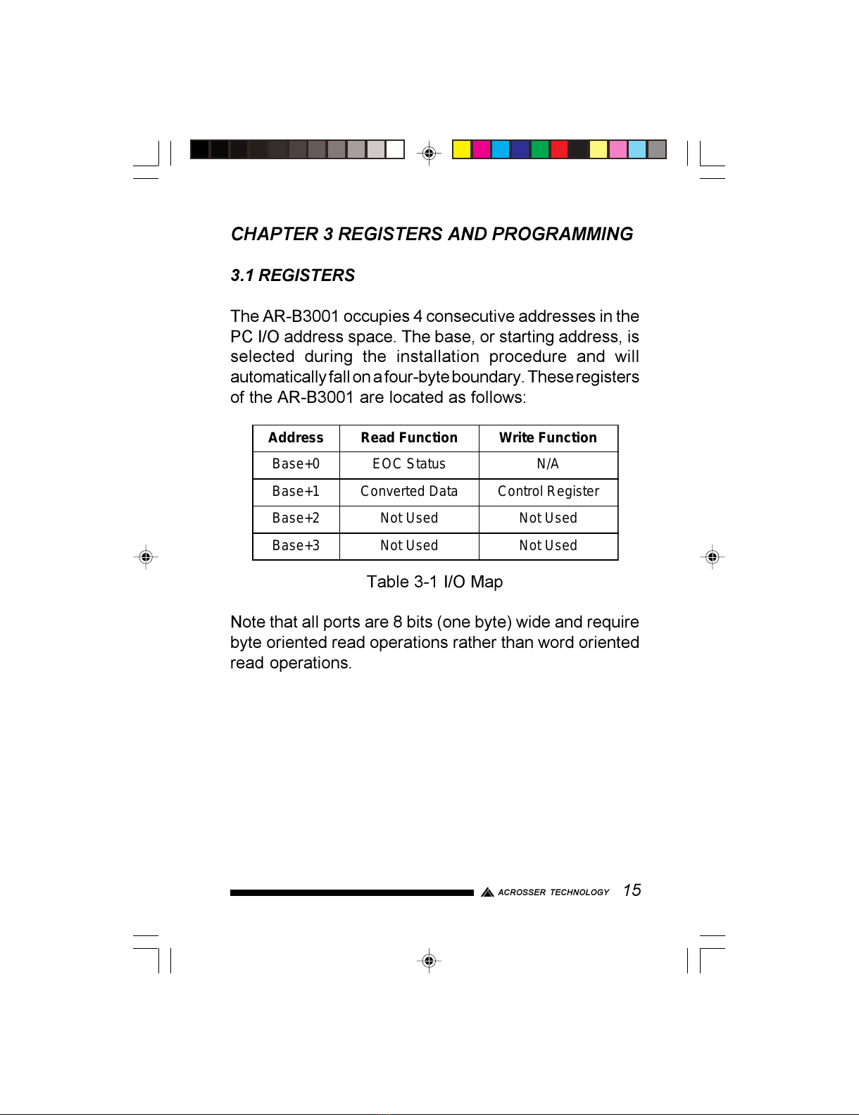
The AR-B3001 occupies 4 consecutive addresses in the
PC I/O address space. The base, or starting address, is
selected during the installation procedure and will
automaticallyfallon afour-byteboundary. Theseregisters
of the AR-B3001 are located as follows:
Address Read Function Write Function
Base+0 EOC Status N/A
Base+1 Converted Data Control Register
Base+2 Not Used Not Used
Base+3 Not Used Not Used
Table 3-1 I/O Map
Note that all ports are 8 bits (one byte) wide and require
byte oriented read operations rather than word oriented
read operations.
All manuals and user guides at all-guides.com

ACROSSER TECHNOLOGY
16
3.2 EOC STATUS REGISTER (BASE+0)
The bit 6 of EOC Status Register is the conversion status
of the A/D converter. This bit will be high(1) during
conversion and will be low(0) when data is available.
Base + 0
D7 D6 D5 D4 D3 D2 D1 D0
XEOC X X X X X X
EOC End of conversion.
EOC = 0 means the A/D converter is in the auto-zero
configurationandis readyforthenext conversion.
The A/D data registers contain valid data of
previous conversions.
EOC = 1 means the A/D converter is busy and the A/D
conversion is in progress.
3.3 CONTROL REGISTER (BASE+1)
Write data to the Control Register controls the operation
of the board. The format of this register is describes as
follows:
Base + 1
D7 D6 D5 D4 D3 D2 D1 D0
X TRIG DL DH CH3 CH2 CH1 CH0
All manuals and user guides at all-guides.com

ACROSSER TECHNOLOGY 17
Trig
Trigger A/D. Write a high(1) to this bit will start the
A/D conversion. This bit can not be high longer than
1/30.5 second. A good practice is to send a high
and then send a low immediately.
DH
Data high enable. ThisbitenablestheA/Dconverter
output the high byte of converted data. DH = 1
enables the A/D converter to output the high byte
data. DH = 0 disables the A/D converter to output
the high byte data.
DL
Data low enable. ThisbitenablestheA/Dconverter
output the low byte of converted data. DL = 1
enables the A/D converter to output the low byte
data. DL = 0 disables the A/D converter to output
the low byte data. Note that DH and DL can not be
high at the same time.
CH0 to CH3
Next channel to be converted. These three bits
control the multiplexer to select an input from the
16(differential) or 8(single-ended) channels of
analog inputs to be converted. The CH3 is the MSB
of channel number and CH0 is the LSB of Channel
number. For example, to select channel 9 as the
input channel, 1001 has to be written to the CH3,
CH2, CH1 and CH0.
X Don't care.
All manuals and user guides at all-guides.com
ACROSSER TECHNOLOGY
18
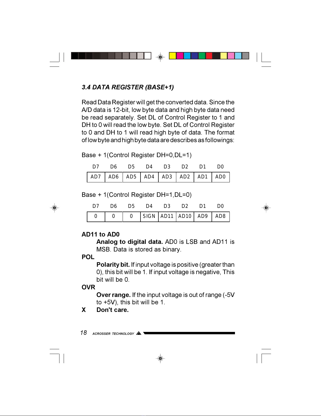
3.4 DATA REGISTER (BASE+1)
Read Data Register will get the converted data. Since the
A/D data is 12-bit, low byte data and high byte data need
be read separately. Set DL of Control Register to 1 and
DH to 0 will read the low byte. Set DL of Control Register
to 0 and DH to 1 will read high byte of data. The format
oflowbyteandhigh byte data are describes asfollowings:
Base + 1(Control Register DH=0,DL=1)
D7 D6 D5 D4 D3 D2 D1 D0
AD7 AD6 AD5 AD4 AD3 AD2 AD1 AD0
Base + 1(Control Register DH=1,DL=0)
D7 D6 D5 D4 D3 D2 D1 D0
0 0 0 SIGN AD11 AD10 AD9 AD8
AD11 to AD0
Analog to digital data. AD0 is LSB and AD11 is
MSB. Data is stored as binary.
POL
Polarity bit. If input voltage is positive (greater than
0), this bit will be 1. If input voltage is negative, This
bit will be 0.
OVR
Over range. If the input voltage is out of range (-5V
to +5V), this bit will be 1.
X Don't care.
All manuals and user guides at all-guides.com
ACROSSER TECHNOLOGY 19
3.5 PROGRAMMING THE AR-B3001 WITH DRIVER
ROUTINES
The AR-B3001 package provides driver routines for
Assembly, BASIC, and C language. Functions covered
by these driver routines include the application of trigger
A/D, and read A/D data. The various functions of the
driver routine are described in this section.
3.5.1 Programming With The Assembly Driver
The source code and object code of the driver routine for
assembly language are provided in the "ASM_LIB sub-
directory of provided diskette. To use the driver routine
with your program, you need to link "A3001LIB.OBJ"
wiith your program. You can also modify the source file
"A3001LIB.ASM" to meet your special requirement.
The assembly driver routine is a far procedure. The name
of this procedure is "ADCLIB". Three functions are
provided. Each function corresponds to an AH value for
entering the service routine. DX register is employed to
specify the base port of AR-B3001. Before calling the
driver routine, AH and DX registers must be specified
according to the function number and base address set
by DIP SW. Function 0 and 2 also need the AL register
bespecifiedwith the channelnumberthatwill be acquired.
On return of each function, AL register contains the
return message code.
All manuals and user guides at all-guides.com
ACROSSER TECHNOLOGY
20
To create executable programs with assembly driver
routine,you havetolinkyourmodulewithA3001LIB.OBJ
as following example.
LINK SAMPLE+A3001LIB;
Function 0 - Select Channel and Trigger ADC
Purpose
This function selects the analog input channel and
sends a pulse to trigger the ADC.
Input Arguments
The following input arguments have to be initialized
before calling the function.
AH = 0, specifies function 0.
AL = Channel number. Valid number is 0 to 7 for
differential input or 0 to 15 for single-ended
input.
DX = The I/O port base address. Base address can be
located between 100H and 3FCH.
Returns
AL = 0, Good return.
= 1, Conversion is already in process.
All manuals and user guides at all-guides.com
Other Acrosser Technology Recording Equipment manuals


