Watts Lync Aegis A User manual

Electronic Controller User Manual
Aegis Sequencer
Disclaimer:
The information contained in this manual is subject to change without notice
from Watts Heating and Hot Water Solutions LLC dba Lync by Watts ("Lync").
Lync makes no warranty of any kind with respect to this material, including, but
not limited to, implied warranties of merchantability and fitness for a particular
application. Lync is not liable for errors appearing in this manual, nor for
incidental or consequential damages occurring in connection with the furnishing,
performance, or use of these materials.
L-OMM-015_0B •8/8/2023
Engineered Solutions
Lync
USA: T: (817) 335-9531
Technical Support - -Fri, 8 am - 5 pm CST
© 2023 LYNC

Aegis Sequencer
Table of Contents
L-OMM-015_0B •8/8/2023 Technical Support •(800) 433-5654 •Mon-Fri, 8 am - 5 pm EST 2 of 38
CONTENTS
1. INTRODUCTION................................................................................................................................3
2.
System Composition
.....................................................................................................................3
2.1. Electrical Connections ...........................................................................................................3
2.2. Ethernet Network....................................................................................................................4
3. Setup ...................................................................................................................................................5
4. User Interface....................................................................................................................................8
4.1. Electrical Panel User Terminal .............................................................................................8
4.2. Main Screen and Control Logic............................................................................................8
4.2.1. Sequence of Operation................................................................................................9
4.2.2. Anti-Legionella Management.......................................................................................9
4.2.3. Secondary Pump Management.................................................................................10
4.3. User Settings.........................................................................................................................11
4.3.1. On/Off........................................................................................................................11
4.3.2. Set .............................................................................................................................11
4.3.3. Anti-Legionella...........................................................................................................12
4.3.4. Info.............................................................................................................................13
4.3.5. Unit Info Menu ...........................................................................................................14
5. Main Menu........................................................................................................................................15
5.1. Access to the Menu and Password Levels.......................................................................15
5.2. Menu Loops and Layout......................................................................................................16
5.2.1. Menu A: Input/Output.................................................................................................16
5.2.2. Menu B: Thermoregulation........................................................................................17
5.2.3. Menu C: Master Parameters......................................................................................17
5.2.4. Menu D: Slaves Parameters......................................................................................18
5.2.5. Menu E: User Settings...............................................................................................18
6. Alarm Management........................................................................................................................24
6.1. Alarm Screens and LED......................................................................................................24
6.2. Alarms Log.............................................................................................................................25
7. Remote Interface............................................................................................................................25
8. Appendix A –Plant Drawings and Sensor Locations ..........................................................26
A.1. Plants with Two Units...........................................................................................................26
A.2. Plants with Three Units........................................................................................................28
A.3. Plants with Four Units..........................................................................................................28
9. Appendix B –Wiring Connections ............................................................................................26
10. Appendix C –Part Numbers........................................................................................................26
11. Appendix D –BAS Communication Points.............................................................................26

Aegis Sequencer
INTRODUCTION
L-OMM-015_0B •8/8/2023 Technical Support •(800) 433-5654 •Mon-Fri, 8 am - 5 pm EST 3 of 38
1. INTRODUCTION
TheAegisSequencercontrollercanbeusedinallsystemswhereseveralAegisheatpumpsareinstalled
parallelto eachother,usingthesamewatertanksystem,andrequiringacommoncontrolpoint.The
systemcanincludeuptosixunits,andcanmanageasecondarysidewaterpump.Thedevicecandetect
the thermal demand of the tanks and activate the appropriate number of units.
Therequired number of units isdeterminedby temperatureprobes located in the tanks.The probes
determinehowmuchpower,andhowmanystepsareactivated,whichwilldetectwatertemperature
stratification in the tanks.
The settings can be changed via the user interface (graphic display) or BMS.
2. System Composition
ThesystemconsistsoftheAegisSequencerelectricalpanelequippedwithwatertemperatureprobesto
be placed in the water tanks (see below), as well as digital I/O to dialogue with third-party building
automationsystems.AnethernetconnectionbetweentheSequencerandtheheatpumpsisrequired.
The Aegis Sequencer ships with the following items:
•Sequencer
•(9) 10 kΩtemperature sensors
•A packet containing the user manual and electrical schematics
•Enclosure key, tied to the power switch
2.1. Electrical Connections
During installation, refer to the wiring diagram in Appendix B.
The probes should be positioned as follows:
•BT1 probe: in the coldest point, i.e. in the lower part of the storage group (return circuit side
towards the units), or at the point where the maximum load set point management of the
storage system happens
•BT2probe: in thehottestpoint,i.e.in theupperpartofthestoragegroup(withthesideofthe
delivery circuit towards the secondary)
•BT3 probe (secondary side pump management): at the outlet of the heat exchanger
•BT4–BT9probes(powersteprequirementprobes):tobedistributedevenlybetweenthetanks
A total of N+1 sensors will be required, where N is the number of heat pumps.
•BTL probe (anti-Legionella probe): at the inlet of the heat exchanger

Aegis Sequencer
System Composition
L-OMM-015_0B •8/8/2023 Technical Support •(800) 433-5654 •Mon-Fri, 8 am - 5 pm EST 4 of 38
2.2. Ethernet Network
TheAegisunits(slaves)connecttotheAegisSequencercascadecontroller(master),viaanEthernet
networkwithastarstructure.ModbusTCPcommunicationprotocolisusedbetweenthemasterandthe
slaves.
The network switch is pre-installed inside the electrical panel.By connecting the switch to the local
network, the end user can access the unit's web server from a local network, or read the system’s
information via BMS.
BoththeindividualAegisunitsandtheAegisSequencermustbesetupwithaconsistentIPaddress(i.e.
part of thesame class network/subnet). Refer to the Aegis control manual, L-OMM-013LyncAegis
ElectronicControllerManualinsection8.12.5.MENU-EtEthernet,fordetailsonhowtosetthenetwork
addressoneachunit.TheaddressesassignedtotheindividualunitsmustbeconfiguredintheManager
in Menu D: Slave parameters.
IntheService-ServiceSettingmenu,foreachheatpumpitisnecessarytosettheparametersaccording
to the image below:
Aegis Sequencer
Setup
L-OMM-015_0B •8/8/2023 Technical Support •(800) 433-5654 •Mon-Fri, 8 am - 5 pm EST 5 of 38
3. Setup
1. Provide 120V power to the unit at the main switch on the top-right of the cabinet. Electrical
protectionandadisconnectswitchmustbefield-providedbyalicensedelectricianasperlocal
code requirements.
2. Usethe10kΩtemperatureprobesprovidedtomakeallconnectionsneededinsideofyourtank
system,asfollows.Thenumberoftemperatureprobesneededisequaltothenumberofheat
pump units installed, plus one (see Appendix B: Wiring Connections).
•BT1: the coldest point of the tank system connects to terminal 1 and GRND2
•BT2: the hottest point of the tank system connects to terminal 2 and GRND2
•BT3: the outlet of the heat exchanger connects to terminal 3 and GRND2
•BTL: the inlet of the heat exchanger connects to terminal 4 and GRND2
•BT4-BT9:spreadevenlythroughoutthetanksystemandallconnectintotheconsecutive
terminals and GRND2s
3. Forinstallationswithadedicatedheatexchangerandprimarypumpforeachheatpump,the
pumps must be wired into the individual heat pumps. (See L-OMM-013)
Ifonlyonepumpandheatexchangerisbeingusedforallheatpumpunits,thesingle
primarypumpmustnowbewiredintotheSequencer.Thepumpshouldbeconnected
into terminals 103 and 104. (see Appendix B Wiring: Connections).
Pleasenote:ThisisnotarecommendedapplicationastheLyncheatexchangermodules
are only designed to work with a single heat pump.
4. EachunitmustbeconnectedintotheethernetswitchinsideoftheSequencer.Remotecontrols
or BMS are also accessed through the ethernet switch.
•The first port is used to connect the ethernet switch and the control board of the
Sequencer. This connection is factory-made.
•The second switch port is dedicated to connect the remote control or BMS.
•Theethernetports3-8 arefortheconnectiontoeachheatpumpin orderfromunits1
to 6.
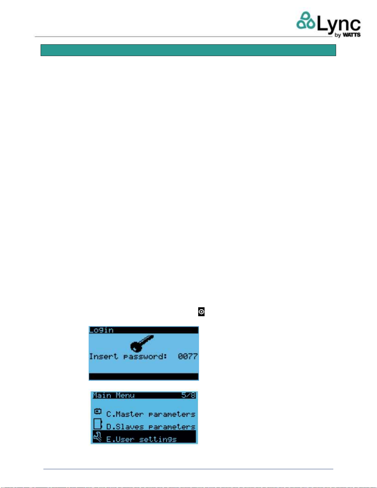
5. Configure the Network Settings of The Sequencer as follows:
I. PresstheprogrambuttonPRG orthe buttonontheremoteinterfaceandenterthe
user password, 0077.
II. Go to E. User Settings and press enter.

Aegis Sequencer
Setup
L-OMM-015_0B •8/8/2023 Technical Support •(800) 433-5654 •Mon-Fri, 8 am - 5 pm EST 6 of 38
III. Go to d. Network Configuration tab and press enter.
IV. Input the following settings:
•Enable: Static
•Set IP address to 192.168.1.152
•MASK: 255.255.255.000
•GW: 192.168.1.1
•DNS: 192.168.1.1
6. SearchandrecordtheIPaddressofeachAegisAheatpumpbeingconnectedtothesequencer.
SettheSlaveparameterstomatchtheIPaddressofeachunitinorder.Tosettheseparameters
for each unit:
I. PressprogrambuttonPRGorthe buttonontheremoteinterfaceoftheSequencer.
II. Enter Service password 0077.
III. Scroll down to Slaves parameters.
IV. ChangetheIPaddressoftheunitinsidetheSequencertomatchtheIPaddressoneach
heat pump.

Aegis Sequencer
Setup
L-OMM-015_0B •8/8/2023 Technical Support •(800) 433-5654 •Mon-Fri, 8 am - 5 pm EST 7 of 38
V. EnsuretheSlaveID#ismatchesthenumberoftheunit(example:Unit3hasSlaveID3).
VI. Repeat these steps until all units have their matching IP addresses in the Slave
Parameters.
7. DisableTemperatureProbesBT1andBT2foreachunit. Thesesettingsareaccessedthroughthe
remote interface of each unit.
I. Using a browser, enter the IP address of a unit into the address bar. For more
information on the remote interface, reference L-OMM-013.
II. Select User Setting.
III. Set temperature probes BT1 and BT2 to DISABLED.
Ifindividualunitheatexchangermodulesandprimarypumpsarebeingused,thesepumpsmust
be ENABLED in the Service menu.
Ifasingleexternalheatexchangerandprimarypumpisbeingused,theindividualunitprimary
pumps must be DISABLED in the Service menu.
Pleasenote:Thisisnotarecommendedapplication,astheLyncheatexchangermodulesare
only designed to work with a single heat pump. Note that this is not a recommended
application.
8. Ensure that there are no errors or alarms displayed. Hold the alarm button down for three
secondstoresetallalarms.Pressthealarmbuttontocheckforthestatusofthealarms.Ifnone
are present the alarm screen will appear as follows:
Aegis Sequencer
User Interface
L-OMM-015_0B •8/8/2023 Technical Support •(800) 433-5654 •Mon-Fri, 8 am - 5 pm EST 8 of 38
4. User Interface
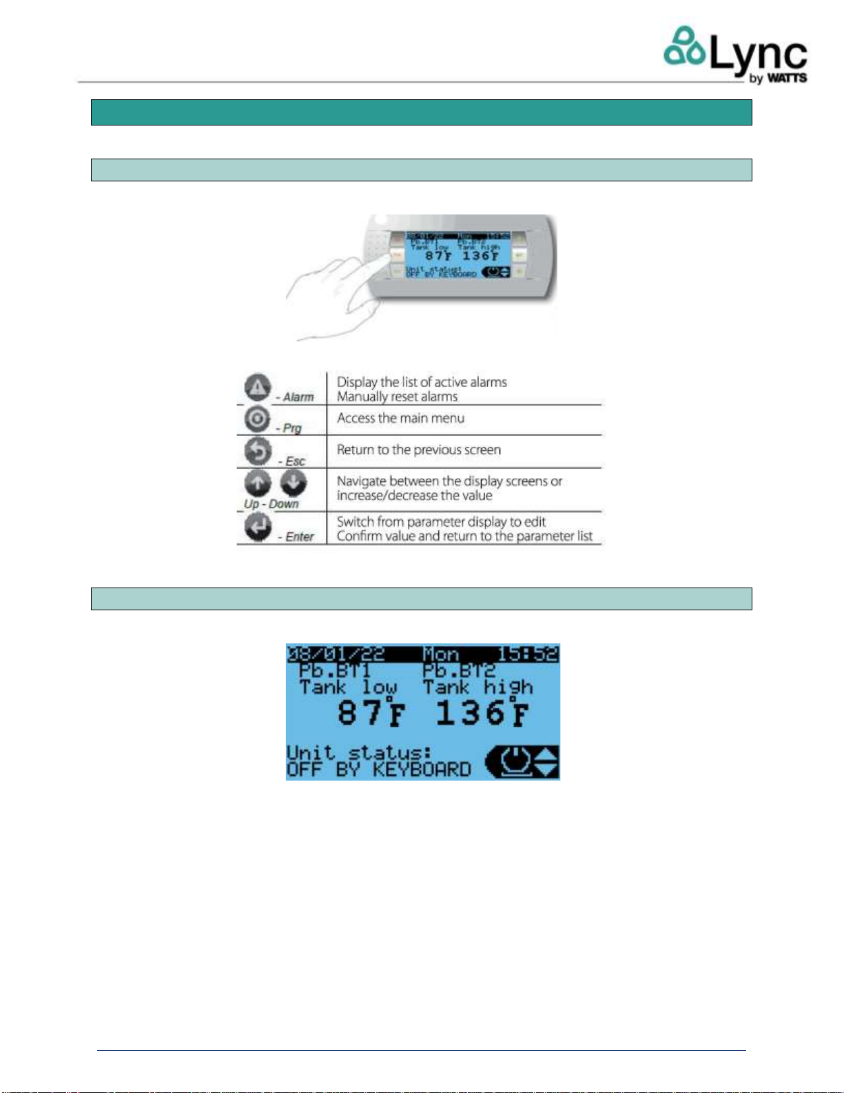
4.1. Electrical Panel User Terminal
The user interface is an electrical panel with a semi-graphic terminal.
The terminal has six physical buttons, which function as follows:
4.2. Main Screen and Control Logic
The main screen, which is the default display, shows the following information for the unit:
•BT1 probe value (tank low/cool side probe)
•BT2 probe value (tank high/hot side probe)
•ON/OFF alarm status
•System date and time

Aegis Sequencer
User Interface
L-OMM-015_0B •8/8/2023 Technical Support •(800) 433-5654 •Mon-Fri, 8 am - 5 pm EST 9 of 38
4.2.1. Sequence of Operation
Temperaturecontrolisonlyactivewhenthesystemisturnedon.Whenthesystemisturnedoff(from
thekeyboard,BMS,digitalcontact,etc.),thecontrolpanelonlyreceivesdatafromtheunitsanddisplays
any anomalies (e.g. offline units).
TheAegisSequenceractivatestheslaveunitsinorderbasedonthevalueofthetemperatureprobes
positioned inthestoragesystem.TheBT1andBT2probes,whichhavetwoindependentsetpoints,
function as follows:
•ProbeBT1:IfthesetpointfortheBT1probeisreached,otherunitscanbeactivated,unlessthe
set point for the BT2 probe is reached.
•ProbeBT2:IfthesetpointfortheBT2probeisnotreached,aheatpumpwillbeforcedon,even
if set point on probe BT1 is reached.
•ProbesBT4–BT9:Theadditionalprobesareassociatedwithdistinctpointsanddifferentials,
calculated by adding an offset to the set referred to as BTL. Except for the management
associated with the BT1 and BT2 probes, each unsatisfied set will raise the request for an
additional unit to activate.
See Section 4.3, User Menu, for more information on menu settings.
4.2.2. Anti-Legionella Management
TheAegisSequencerincludesacontrolalgorithmcalled“anti-Legionellafunction.”Thisfunctiondoes
notapplytotheNorthAmericanmarketandshouldnotbeusedbecausetherequiredheatexchanger
moduleisnotcompatiblewiththisfeature.Theinformationinthissectionisincludedforreferenceonly.
Theanti-Legionellafunctioncanbeactivatedeitheronasetscheduleormanuallyviatheinterfaceor
BAS.
NOTE:Theanti-LegionellafunctionmaybeusedtomitigatetheriskofwaterborneLegionellainthe
tankarrayandnear-tankpiping. Thisfunctionwillnotautomaticallydisinfectbuildingsystempiping.
Aproper waterbornepathogenmitigationstrategyshouldbeused. SeeASHRAEStandard188.
The BTL probe placed at the inlet of the heat exchanger is required to manage the anti-Legionella
function. The anti-Legionella cycle consists of two phases:
1. Phase 1
•The "Anti-Legionella active" relay contact is closed.
•All the units are forced to a set point value of 194°F [90°C] (settable value).
•With BT1 up to Phase 1 Set BTL (e.g. 140°F [60 °C] settable value), all heat pumps are
activated.
•WithBT1overPhase1SetBTL,thesystemkeepsonlyoneunitactiveuntilthetemperature
oftheBTLprobereachesapredefinedPhase1SetBTLsetpoint,presetat131°F[55°C].
The set point must be lower than the parameter ''Maximum inlet water temperature" set on the
Aegis unit. This function is only available on units with High Inlet Temperature function.
⚠WAR NIN G!
Itisrecommendedthatthisfunction,ifused,bescheduledforperiodsoflowdemandtoreducethe
riskofscalding.Amastermixingvalveand/orpoint-of-usemixingvalveisrequiredtopreventscalding.
Lync recommends the DigiTemp line of digital mixing valves.

Aegis Sequencer
User Interface
L-OMM-015_0B •8/8/2023 Technical Support •(800) 433-5654 •Mon-Fri, 8 am - 5 pm EST 10 of 38
2. Phase 2
•WhenthePhase1SetBTLsetpointisreached,theunitswillswitchoff(compressorOFF),
while the secondary pumpis brought to a fixed speed. Once theBTL probe reaches the
Phase 2 Set BTL (e.g. 158°F [70°C], the secondary pump also switches off.
•The anti-Legionella cycle is finished once this condition lasts for a settable time frame
(default 60 seconds).
•Themaximumallowabledurationoftheanti-Legionellacycleissettoadefaultof[2min],
after which the unit exits the cycle and returns to normal operation. This generates a
warning that the anti-Legionella cycle was not completed correctly.
•TheunitdefrostfunctionhaspriorityovertheAegisSequenceranti-Legionellamanagement.
Sections 4.2.2. and 4.3.3. contain more information on anti-Legionella.
4.2.3. Secondary Pump Management
Thesecondarypumpmanagementallowscoordinatedoperationbetweentheprimarypumpsinstalled
inside the units or on the primary loop and those on the domestic (secondary) side between the
intermediateexchanger andthestoragetanks.Thecoordinatedoperationofpumpsisnecessaryto
ensure the correct delivery temperatureofthewaterto the tanksystem.Thesecondary pumpcould
have a different flow than what’s installed on the unit, and must be managed independently by an
additional temperatureprobe, positioned downstream ofthe intermediate exchanger (see5.2.3for
information on the settings).
Aegisheatpumpwaterheatersaresuppliedwithanengineeredheatexchangermodule,sizedforan
individualheatpump. While the Aegissequencercansupportasingle,sharedheatexchangerand
pump, Lync strongly recommends using individual heat exchangers and pumps for multiple unit
applications.
Please note that the speed regulation of the domestic side pump is independent from the speed
regulation of the primary pump.
The function is based on the following:
•proportional-integral-derivative control, which has as an input value
•the temperature value read by the BT3 probe
•its position at the exchanger outlet
•two temperature setpoints:
oUnit delivery setpoint
oAnti-Legionella setpoint (if the function is active)
An additional fixed speed set point is needed for the anti-Legionella Phase 2.
See 5.2.2 for more information on Thermoregulation.

Aegis Sequencer
User Interface
L-OMM-015_0B •8/8/2023 Technical Support •(800) 433-5654 •Mon-Fri, 8 am - 5 pm EST 11 of 38
4.3. User Settings
Onthemainscreen,theUP andDOWN buttonscanbeusedtoscrollthroughtheusermenuof
basicfunctions.UsetheENTER buttontoselectoptions.Nopasswordisneededtoaccessandedit
these functions.
4.3.1. On/Off
Thesystemcanbeturnedonandofffromtheusermenu.Thestatusisdisplayedonthemain
screen,andcanbechangedusingtheUPandDOWNkeys.TheOFFoptiononthescreenhas
priority over the ON/OFF commands from digital input or BMS.
4.3.2. Set
Through the set point menu, it is possible to:
1. Define the set points forprobesBT1andBT2andthecorrespondingdifferentialbands.
2. DefinethesetpointsrelatedtoprobesBT4–BT9.Bydefault,thesetpointisautomatically
calculated. To use a custom set point, manually change the option"Enable autoset" to
"NO" and change the value in the "Manual set" field.

Aegis Sequencer
User Interface
L-OMM-015_0B •8/8/2023 Technical Support •(800) 433-5654 •Mon-Fri, 8 am - 5 pm EST 12 of 38
4.3.3. Anti-Legionella
Through the anti-Legionella menu, it is possible to do the following:
1. Enabletheanti-Legionellafunction anddefinetherecurringstartingtime(day,
hour, and minute). The maximum time for a forced exit can also be defined.
2. Define the BT1 and BTL set points, and the fixed speed pump set.
3. Viewanti-Legionellastatus(phase1runningorcompleted,phase2elapsedtime).
4. Manually start and stop the function.

Aegis Sequencer
User Interface
L-OMM-015_0B •8/8/2023 Technical Support •(800) 433-5654 •Mon-Fri, 8 am - 5 pm EST 13 of 38
4.3.4. Info
Through the info menu, you can view the following:
1. Thegeneralstatusofthesystem(tanktemperatureprobesandplantpowerrequest).
2. Status of the secondary side (set point, supply water temperature, current speed).
3. The basic information of the individual units (unit inlet water temperature and gas-
cooler outlet, pump speed, power required by the Sequencer).
oPlant request: Plant (system) power request
oIn: Unit inlet water temperature
oOut: Unit outlet water temperature
oPwr: Power requested to the unit
oPmp: Pump
4. Software and firmware information.

Aegis Sequencer
User Interface
L-OMM-015_0B •8/8/2023 Technical Support •(800) 433-5654 •Mon-Fri, 8 am - 5 pm EST 14 of 38
4.3.5. Unit Info Menu
Throughthese menus,itispossibletodisplaydetailedinformationontheunitsconnected
to Aegis Sequencer:
1. UnitoperatingmodeandstatusofremoteOFFdigitalcontact(withopencontact
theunitisforcedOFFandisnolongeravailablefortheSequencerregulation).
2. Unit set ST1: Supply water temperature set point used by the unit
3. Unit pump: Current unit pump speed
4. AI01 –Al12: Unit temperature and pressure probe values

Aegis Sequencer
Main Menu
L-OMM-015_0B •8/8/2023 Technical Support •(800) 433-5654 •Mon-Fri, 8 am - 5 pm EST 15 of 38
5. Main Menu
Regardlessofthedisplayedscreen,pressingtheprogrammingkeyaccessesthepasswordentryscreen,
which allows access to the main menu shown below.
The program has three different password levels with different permissions:
•USER: Can change the basic settings (e.g. date/time), Default password: 0001
•SERVICE:(technical/maintenanceassistance)Letsthetechnicianmodifysomeoperating
parameters. This setting is reserved for technical assistance centers and authorized
personnel. The default password is 0077.
•MANUFACTURER: Allowsviewingandeditingaccesstoallparameters.The default
password is 0528.
Ineachscreen,theaccessneededtoedittheparametersisshownintheupperleftcorner,alwayswith
the same codes. An example follows (M: Manufacturer, S: Service):
Oncethepasswordisentered,thesystemwillbeunlockedforfiveminutesfromthelasttimeakeywas
pressed,afterwhichthepasswordwillneedtobere-enteredtoaccesstheparametersoftheadvanced
functions. To log out without waiting 5 minutes, use the menu G. Log-Out.

Aegis Sequencer
Main Menu
L-OMM-015_0B •8/8/2023 Technical Support •(800) 433-5654 •Mon-Fri, 8 am - 5 pm EST 16 of 38
5.1. Menu Loops and Layout
Ineachmenu,thescreensareorganizedintoloops:theUPandDOWNbuttonsscrollallthescreensin
thesamemenu.Thescreensareorganizedsothatthedownbutton(scrollingdownwards)accessesthe
most frequently used screens, while those that are used least (e.g. configuration) are accessed by
pressing the up button (scrolling upwards).
The individual menus use a code that helps identify the menu:
•1st character (uppercase): main menu code
•2nd character (lowercase): submenu, if any
•3rd character (number): index inside the loop
Example:clocksetting,menucodeDa1includesMenuD.UserSettings,sub-menua.Date/Time,and
first menu screen of the loop “1”
5.1.1. Menu A: Input/Output
IntheA.Input/Outputmenuitispossibletochangetheactionsofdigitalinputsandoutputstonormally
open or normally closed.
Menu A01: Turning the system on/off by digital input and choice of NO/NC.

Aegis Sequencer
Main Menu
L-OMM-015_0B •8/8/2023 Technical Support •(800) 433-5654 •Mon-Fri, 8 am - 5 pm EST 17 of 38
MenuA02:EnablingthesystemalarmwithaforcedstopviaexternaldigitalinputandchoiceofNO/NC.
5.1.2. Menu B: Thermoregulation
The B. Thermoregulation menu can be used tomodify the operatingset pointof the individual units.
MenuB01: Setpointsaretransmittedtotheslaveunitsinnormaloperatingmode,andduringtheanti-
Legionella cycle. The actual set point in use is also displayed.
5.1.3. Menu C: Master Parameters
Through the C. Master parameters menu, it is possible to modify the operating parameters of the
secondary pump to adapt it to the individual installations.
Menu C01: Enabling of the secondary pump function and pump offset/PID parameters.

Aegis Sequencer
Main Menu
L-OMM-015_0B •8/8/2023 Technical Support •(800) 433-5654 •Mon-Fri, 8 am - 5 pm EST 18 of 38
MenuC02:Enablingofpumpmanualoperationanddefiningpumpmin/maxlimits. Thismodeallows
you manually set the pump speed within the low and high limits.
5.1.4. Menu D: Slaves Parameters
ThroughtheD.Slavesparametersmenu,itispossibletodefinetheslaveAegisdevicesIPaddresses.
MenuD01:SlavedeviceIPaddress.TheSlaveIDandofflinedelayparameterscanbeleftonthefactory
defaults.
5.1.5. Menu E: User Settings
TheE.Usersettingsmenuismadeupofseveralsubmenus,throughwhichyouaccessthefollowing
screens:

Aegis Sequencer
Main Menu
L-OMM-015_0B •8/8/2023 Technical Support •(800) 433-5654 •Mon-Fri, 8 am - 5 pm EST 19 of 38
•a. Date/Time: Date and Time Settings –Menu Ea1
•b. UoM: Unit of Measure –Menu Eb1
Menu Eb1: Unit of Measure shown on the display
Menu Eb2: Unit of measure used on the web interface

Aegis Sequencer
Main Menu
L-OMM-015_0B •8/8/2023 Technical Support •(800) 433-5654 •Mon-Fri, 8 am - 5 pm EST 20 of 38
•c. Language: System Language Settings –Ec1
"Showmasktime"istheidlecountdown.Whenthetimerrunsoutthedisplaygoesbacktothe
main screen. When a button is pressed the 30 second timer starts over.
•d. Network: Serial and Ethernet Port Configurations and On/Off options –Ed1
Note that any changes to the network settings will require a reboot of the sequencer
Menu Ed2: Modbus and BACnet Protocol Parameters
This manual suits for next models
1
Table of contents
Other Watts Recording Equipment manuals


Popular Recording Equipment manuals by other brands

Dedicated Micros
Dedicated Micros PICKAPOINT user guide

IntesisBox
IntesisBox ME-AC-MBS-1 user manual

Talon
Talon RTS 2706 operating manual

Comunello Automation
Comunello Automation GINDEXSTN0B00A Installation and user manual

Marantz
Marantz DR4160/F1N Service manual

thomann
thomann Harley Benton DNAfx GiT user manual


