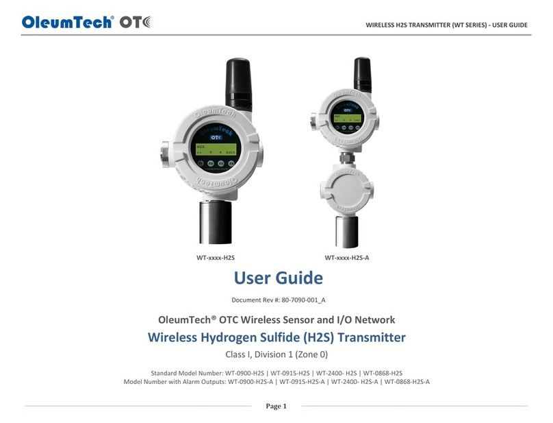
ACS contsys Hydrocont SN50 User manual

10.14
Technical manual
Main features
Finely graded lling level measuring
• Measuring ranges from -1 to 20 bar
• Measuring spans from 0,05 to 20 bar
Ceramic membrane for various applications
Wide variety of process connections
Optionally process diaphragm seal with metallic membrane
Process temperature range from – 40 °C to +125 °C
Accuracy up to ≤ 0,1%
Xcellence type - Accuracy up to ≤ 0,05%
Integrated evaluation electronic
• 3-wire with current signal 0/4…20 mA
• 3-wire with voltage signal 0...10 V
• 4x PNP switch output
• Bluetooth-Interface
Enclosure and display rotatable for optimal operability in
each installation position
Viewing angle optimized TFT-LCD display for best
readability
Easy handling by clear menu navigation
Extensive diagnostic functions for system analysis
Measure data memory for up to 1 million measuring values
Hydrocont SN50
Hydrostatic lling level transmitter
Measurement of lling levels in liquids

ACS-CONTROL-SYSTEM GmbH l Lauterbachstr. 57 l D-84307 Eggenfelden l www.acs-controlsystem.de l [email protected]
2
You have purchased a high-grade and modern measuring device of ACS-CONTROL-SYSTEM GmbH.
We want to give thanks for your purchase and for your condence to us.
The actual technical manual includes instructions for installation, electrical connection and inauguration,
as well as the technical data of the device.
Modications, that answer the purpose of the technical progress, are reserved by
ACS-CONTROL-SYSTEM GmbH without prior notice.
If a question occurs, that can‘t be answered by the listed informations, please call on our technicians
team in Eggenfelden Tel: +49 8721/ 9668-0 or [email protected]
All rights reserved

ACS-CONTROL-SYSTEM GmbH l Lauterbachstr. 57 l D-84307 Eggenfelden l www.acs-controlsystem.de l [email protected] 3
Index
Application 4
Function 4
Measuring principle 4
Pressure diaphragm seal 4
Signal processing 5
Safety notes 5
Installation6
Installation place 6
Process and environmental temperature 6
Installation notes 6
Air pressure compensation 6
Process diaphragm seal 7
Electrical connection 8
Potential equalization - earthing 8
Connection cable 8
Supply voltage 8
Load resistor 9
Connection scheme 10
Operation 11
Operation and display parts 11
Function scheme 12
Menu structure 14
Navigation 15
Output 16
Basic Setting 21
Display 27
Simulation – extended menu structure 32
Diagnose 33
Data 35
Start-up procedure 39
Maintenance43
Repair44
Technical Data 45
Auxiliary power supply 45
Output Signal 0…20mA 45
Output Signal 4…20mA 45
Output Signal 0…10V 45
Output Switch output 45
Output Bluetooth-Interface 46
Measuring accuracy 46
Mounting position 46
Process conditions 47
Environmental conditions 48
Materials - process wetted 48
Materials - not process wetted 49
Data memory 49
Dimension drawings50
Terminal enclosure 50
Temperature decoupler 50
Process connection 51
Order Code 59

ACS-CONTROL-SYSTEM GmbH l Lauterbachstr. 57 l D-84307 Eggenfelden l www.acs-controlsystem.de l [email protected]
4
Application
The device is an electronic hydrostatic lling level transmitter for continuous measuring of lling levels
in liquids within pressure-less container.
The use of a capacitive measuring sensor with ceramic membrane and the corresponding excellent
characteristics, allows the use in nearly all elds of industry.
Optionally the device can be equipped with a process diaphragm seal.
The use of a pressure diaphragm seal with metallic membrane leads to an extension of the application
range of the device.
Pressure diaphragm seals are applied to a measuring device:
• if the process wetted parts, due to the corrosion resistance, must be made of special
materials, that are not suitable for the construction of elastic measuring elements of pressure
measuring devices.
• if measured materials are toxic or ecologically harmful and should not escape into environment
or into the atmosphere, e.g. at leakage of the measuring sensor due to overpressure resp.
wear, and thus, using the pressure diaphragm seal, an additional protection is placed ahead to
the measuring device.
• if the environmental temperature at the measuring place or the temperature of the measured
material it too high for the measuring device and is kept away from it by using a pressure
diaphragm seal with temperature decoupler or capillary line.
• if the installation situation at the measuring place are unsuitable of if mechanical vibrations
and pulsations must be kept away from the measuring device and due to the use of a pressure
diaphragm seal with capillary line the measuring device is mounted away from the measuring
place at a suitable place.
Function
The device is used for lling level measurement by recording the hydrostatic pressure.
The device is mounted in the wall of the container or as a suspend device above the container.
Measuring principle
The height of the liquid column over the measuring membrane causes on the measuring membrane
the so-called hydrostatic pressure, that is dened besides the height of the liquid column also by the
density of the liquid and the gravitational constant.
h = p / (ρ * g)
h >> height (lling level)
p >> pressure
ρ >> density of the liquid
g >> gravitational constant
The hydrostatic pressure of the liquid is applied to the ceramic membrane and causes there a variation
of the capacity at the back side of the membrane.
The ceramic capacitive membrane offers excellent characteristics like highest pressure and pressure
blow strength, vacuum resistance, very high resistance against chemicals, corrosion and abrasion as
well as very good insensitiveness against temperature shocks, highest accuracy and reproducibility,
good long term stability and a very low temperature inuence.
The ceramic capacitive sensor is a dry sensor, that does not need the use of a pressure transmitting
liquid.
Pressure diaphragm seal
The hydrostatic pressure of the liquid is applied to the metallic membrane of the pressure diaphragm
seals and is transmitted by a pressure transmitting liquid to the backside positioned membrane. The
pressure causes there a variation of the capacity at the back side of the membrane.
The metallic membrane offers excellent characteristics like a very high process temperature range,
vibration decoupling as well as an additional process separation.

ACS-CONTROL-SYSTEM GmbH l Lauterbachstr. 57 l D-84307 Eggenfelden l www.acs-controlsystem.de l [email protected] 5
Safety notes
Each person that is engaged with inauguration and operation of this device, must have read and
understood this technical manual and especially the safety notes.
Installation, electrical connection, inauguration and operation of the device must be made by a
qualied employee according to the informations in this technical manual and the relevant standards
and rules.
The device may only be used within the permitted operation limits that are listed in this technical
manual.
Every use besides these limits as agreed can lead to serious dangers.
The materials of the device must be chosen resp. checked for compatibility with the respective
application requirements (contacting materials, process temperature). An unsuitable material can lead
to damage, abnormal behavior or destruction of the device and to the resulting dangers.
The sensors may not be used as sole device for prevention of dangerous conditions in machines and
plants.
This measuring device meets article 3 (3) of the EC directive 97/23/EC (pressure equipment device
directive) and is designed and produced in good engineer practice.
The device meets the legal requirements of all relevant EC directives.
Using the device in a manner that does not fall within the scope of its intended use, disregarding
this instruction, using under-qualied personnel, or making unauthorized alterations releases the
manufacturer from liability for any resulting damage. This renders the manufacturer‘s warranty null
and void.
Signal processing
The pressure signal, that is transmitted by the membrane to the sensor is converted into an electrical
signal and processed by the integrated evaluation electronic according to the respective preferences.
The measuring value is diagrammed at the display, whereby it can be selected between different
display styles (digital value / manometer / chart / bar graph).
In the internal ring memory up to 1 million measuring values can be recorded durable.
The measuring value can be converted into a continuous current signal 0/4...20 mA resp. voltage
signal 0...10 V or monitored by four PNP switch outputs for exceedance of limit values.
By the use of the Bluetooth interface records measuring values can be downloaded. Moreover the
conguration data can be downloaded or uploaded. This allows a fast and simple conguration of
multiple devices with the same preferences.
Additional functions can be realized on request:
• Real-time-clock for storing of the measuring values with time signature (data logger)
• Communication interface RS485 (different protocols, e.g. Modbus)
• Communication interface USB (Slave)
• Communication interface UART
• Detection of the process temperature

ACS-CONTROL-SYSTEM GmbH l Lauterbachstr. 57 l D-84307 Eggenfelden l www.acs-controlsystem.de l [email protected]
6
Installation
The correct function of the device within the specic technical data can only be guaranteed, if
the permitted process and environmental temperatures (see chapter „Technical data“) will not be
exceeded.
Installation place
The installation of the device at locations where high pressure blows can occur should be avoided.
At a lling level measurement in liquids, the device should be installed below the lowest measuring
point. Do not mount the device in the ll ow, in the suction area of a pump, in the tank outlet or at
a point in the container which could be affected by pressure pulses from an agitator. Calibration and
functional test can be carried out more easily if you mount the device after a shut-off device.
The installation position has inuence on the measuring result of the kind of a zero value shift because
of the deadweight of the measuring membrane. The correction of this deviation at the device is
possible.
Process and environmental temperature
The installation of the device should be made if possible at temperature calmed places to get a reliable
measuring result.
Strong temperature steps, e.g. at lling of a hot liquid into a cold system, can produce a short-time
higher measuring signal deviation.
Temperature compensation takes effect after several minutes. Internal temperature compensation is
faster the smaller the jump in temperature and the longer the time interval involved.
At a large amplication of the measuring signal this deviation will be also amplied accordingly.
The deviation will be completely neutralized after the adaptation of the measuring membrane to the
temperature.
At a step from +20°C ...+80°C this neutralization can wile up to 3 minutes.
The use of a measuring system with process diaphragm seal can cause an essential improvement.
At high process temperatures a heat transfer to the terminal housing can be reduced by isolation of
the medium carrying part of the plant, by the use of a temperature decoupler or of a measurement
system with process diaphragm seal.
Installation notes
Drive the system pressure free prior installation resp. deinstallation of the sensor.
The installation of the device into a closed off completely with process liquid lled connection can lead
to destruction of the measuring membrane. The reduction of the volume of the liquid at screw-in leads
to a very high pressure boosting, that can exceed the permitted maximum value by a multiple. Thus,
before installation, the connection must be sufciently emptied.
The screw-in of the thread process connection by using the terminal housing, the connection plug
resp. the connection cable is not permitted.
The tightening of the thread process connection may only be done at the hexagon by a suitable
spanner and with the maximum permitted torque strength.
The maximum permitted torque strength is:
Thread process connection G ½" 20 Nm
other thread process connection 50 Nm
The housing can be rotated every time, also at operation, mechanically by 330°.
The display can be rotated every time electrically by 180°.
Air pressure compensation
Avoid the damaging or pollution of the pressure compensation system.
The hindrance of the pressure compensation can lead to faulty measuring results.
The lter element of the pressure compensation system is positioned in the bottom of the enclosure.

ACS-CONTROL-SYSTEM GmbH l Lauterbachstr. 57 l D-84307 Eggenfelden l www.acs-controlsystem.de l [email protected] 7
Process diaphragm seal
A process diaphragm seal together with the measuring transmitter forms a closed, calibrated system,
that is lled by openings in the process diaphragm seal and in the measuring system of the measuring
transmitter. These openings are sealed and may not be opened.
The standard reference temperature for pressure diaphragm seal systems is +20°C.
Different temperatures of environment or process causes an additional measuring error.
Process temperatures, that differs from +20°C can be considered by factory, if they are noted at an
order.
The temperature inuences can be minimized by:
• suitable lling uids
• diameter of membrane as big as possible
• keeping away the measuring sensor apart from the temperature by using a temperature
decoupler (required at temperatures from +100°C to +250°C) or a capillary line (required at
temperatures > +250°C) between pressure diaphragm seal and measuring device.
Device with capillary line
• If the measuring device and the pressure diaphragm seal are not mounted on the same level,
this difference in height affects the measuring result due to the hydrostatic pressure of the
uid column of the lling uid.
• At an order a level difference must be urgently noted, to enable a special adjustment for
minimizing the resulting measuring error.
• If vacuum occurs or might possibly occur, the measuring device has to be mounted at least 40
cm below the pressure diaphragm seal.
• At systems with capillary line the measuring speed can be decelerated. This delay is
conditioned by the system.
• Never use the capillary line of a pressure diaphragm seal to carry or move the device. The
welding connections should never be stressed more than unavoidable. Take especially care
never to buckle the capillary line. This would rise the oating time or even cause a leakage
due to which the complete system would lose its function.

ACS-CONTROL-SYSTEM GmbH l Lauterbachstr. 57 l D-84307 Eggenfelden l www.acs-controlsystem.de l [email protected]
8
Electrical connection
The electrical connection of the device must be carried out according to the respective country specic
standards.
Incorrect installation or adjustment could cause applicationally conditioned risks.
Potential equalization - earthing
The device must be grounded.
The earthing can be carried out by the metallic process connection.
The metallic parts of the device are electrically connected with the socket of the plug M12.
Connection cable
Use only shielded signal and measurement wires and install these wires separated from power leading
wires.
Connect the cable shield of a connected cable only at one side to earth, ideally at the installation place
of the device.
Supply voltage
The voltage applied to the terminal contacts may not exceed the maximum permitted supply voltage
to avoid damage of the electronic.
The maximum permitted supply voltage range at the respective setting is:
Signal 0/4…20mA 9…33VDC
Signal 0…10V 14…35VDC
All connections are reverse polarity protected.

ACS-CONTROL-SYSTEM GmbH l Lauterbachstr. 57 l D-84307 Eggenfelden l www.acs-controlsystem.de l [email protected] 9
Load resistor
Signal 0/4…20 mA
A load resistor, e.g. the measuring shunt of an evaluation device, requires a minimum supply voltage.
Dependent on the connected supply voltage, it results in a maximum value for this resistor, where a
correct function is still possible.
This resistor can be calculated by the following term:
RLmax = (US - 7 V) / 20mA
RLmax = maximum load resistor
US = connected supply voltage
Load resistor characteristic
Signal 0…10 V
A load resistor, e.g. the measuring shunt of an evaluation device, requires at a denitive output
voltage an output current. Due to the limitation of that output current, it results in a minimum value
for this resistor, where a correct function is still possible.
This resistor can be calculated by the following term:
RLmin = UOut / 3mA
RLmin = minimum load resistor
UOut = output voltage
Load resistor characteristic
Switch output
Inductive loads at the pnp switching outputs, e.g. relays or contactors may only be used with a free-
wheeling diode or a RC protection circuit to avoid high voltage peaks.
The load at the PNP switching output will be connected to the terminal +terminal of the supply voltage
by a semiconductor switch contactless and by this bounce-free.
At an activated switching state a positive signal near supply voltage is feed to the output.
At deactivated switching state and at failure of supply voltage the semiconductor switch is shut off.
The PNP switching output is current limited to 0,2...0,25 A and is overload and short circuit protected.

ACS-CONTROL-SYSTEM GmbH l Lauterbachstr. 57 l D-84307 Eggenfelden l www.acs-controlsystem.de l [email protected]
10
Connection scheme
Signal 0/4…20 mA / 0…10 V
Conductor color standard connection cable M12:
BN = brown, WH = white, BU = blue
The connection cable in not enclosed in the delivery contents.
Signal 0/4…20 mA / 0…10 V / 2x PNP switch output
Conductor color standard connection cable M12:
BN = brown, WH = white, BU = blue, BK = black, GY = grey
The connection cable in not enclosed in the delivery contents.
Signal 0/4…20 mA / 0…10 V / 4x PNP switch output
Conductor color standard connection cable M12:
WH = white, BN = brown, GN = green, YE = yellow, GY = grey, PK = pink, BU = blue, RD = red
The connection cable in not enclosed in the delivery contents.

ACS-CONTROL-SYSTEM GmbH l Lauterbachstr. 57 l D-84307 Eggenfelden l www.acs-controlsystem.de l [email protected] 11
Operation
Operation and display parts
A – LCD display
• Display of measuring value, device state and operation menu
B - Key Down
• In the selection menu navigation downwards
• In the set menu decreasing of value
• Used, in combination with the key up, for leaving selection and set menu without applying
changings
• Used, in combination with the key up, for a step backwards one menu item
C - Key Enter/Shift right
• Access to operation menu
• In the selection menu entering the selected sub menu
• In the set menu applying the new value and digit shift right
D - Key Up
• In the selection menu navigation upwards
• In the set menu increasing of value
• Used, in combination with the key down, for leaving selection and set menu without applying
changings
• Used, in combination with the key down, for a step backwards one menu item

ACS-CONTROL-SYSTEM GmbH l Lauterbachstr. 57 l D-84307 Eggenfelden l www.acs-controlsystem.de l [email protected]
12
Function scheme
A - Damping
B - Position adjustment
C1 - Primary unit > e.g. bar
C2 - Primary unit > m
D1 - Density > not available (at primary unit bar/mbar)
D2 - Density > e.g. 1,0194 kg/dm3
E - Offset adjustment > e.g. no offset
F1 - Min/Max adjustment > e.g. 0..0,7 bar = 0..100 %
F2 - Min/Max adjustment > e.g. 1..9 m = 0..100 %

ACS-CONTROL-SYSTEM GmbH l Lauterbachstr. 57 l D-84307 Eggenfelden l www.acs-controlsystem.de l [email protected] 13
G1 - Linearization > primary unit - display scaling e.g. 0..0,7 bar resp. 1..9 m = 0..2000 m3
G2 - Linearization > percent 0..100 % - lin. percent 0..100 %
G3 - No linearization
J - Signal output > e.g. 0..100 % = 4..20 mA resp. 0..20 mA resp. 0..10V
K - Error signal evaluation
L1 - Switch / reset switch point S1
L2 - Switch / reset switch point S2
L3 - Switch / reset switch point S3
L4 - Switch / reset switch point S4
M1 - Error indication function S1
M2 - Error indication function S2
M3 - Error indication function S3
M4 - Error indication function S4
N1 - Display scaling > primary unit e.g. 0..100 % = 0..7 bar resp. 1..9 m
N2 - Display scaling > scaled e.g. 0..100 % = 0..2000
O - Display unit > primary unit e.g. bar resp. m or when scaled e.g. m3
P - Error indication display
Q1 - Display - primary unit e.g. 0..1 bar (resp. 0..10 m)
Q2 - Display - scaled e.g. 0..2000 m3

ACS-CONTROL-SYSTEM GmbH l Lauterbachstr. 57 l D-84307 Eggenfelden l www.acs-controlsystem.de l [email protected]
14
Menu structure
The entrance to the different function areas of the selection and set menu layer is done by the main
menu (push the key Enter/Shift right for 3 seconds).
If failures are registered (see chapter diagnose/failure), these are indicated prior the jump into the
main menu.
By the key Enter/Shift right the failure indication will be canceled.
The symbol E at a menu item indicates its position in the extended menu structure.
This extended menu structure can be shown in the submenu display by the menu item menu
structure.
Submenu output
Settings for the function of the switch outputs and the signal output.
Submenu basic setting
Settings for the basic adaption of the device to the measuring task, e.g. adjustment, damping
and linearization.
Submenu display
Settings for the adaption of the measuring value indication to the measuring task, e.g. measuring
value scaling, display type, menu language and also password protection.
Submenu simulation
Settings for the simulation of the switch outputs and the signal output, e.g. for inauguration or
also for failure analysis.
Submenu diagnose
Multiple information to the historical measuring activity and the device, that can be useful for
system surveillance or also for failure analysis.
Submenu data
Settings for the measuring value recording and the data transmission by Bluetooth.

ACS-CONTROL-SYSTEM GmbH l Lauterbachstr. 57 l D-84307 Eggenfelden l www.acs-controlsystem.de l [email protected] 15
Navigation
The navigation in a submenu and in a selection window is done by the keys Up and Down.
The selection of a submenu and the selection of a setting in a selection menu is done by the key
Enter/Shift right.
The jump backward from a submenu to the higher-level menu is done by the menu item back or by
the simultaneous pushing the keys Up and Down.
The leaving of a selection menu without applying the changings is done by the simultaneous pushing
the keys Up and Down.
The input of a value or text in a set menu is done digit by digit.
For the changing of the selected digit the keys Up and Down are used.
For the changing of the digit the key Enter/Shift right is used.
The applying of a set value resp. text is done by pushing the key Enter/Shift right for 3 seconds.
The leaving of an set menu without applying a value resp. text is done by the simultaneous pushing
the keys Up and Down.
After 5 minutes of inactivity the active submenu resp. selection menu will automatically be left and a
change to the measuring value indication is executed.
A jump backward is not executed from an active set menu.

ACS-CONTROL-SYSTEM GmbH l Lauterbachstr. 57 l D-84307 Eggenfelden l www.acs-controlsystem.de l [email protected]
16
Output
The symbol E at a menu item indicates its position in the extended menu structure.
This extended menu structure can be shown in the submenu display by the menu item menu
structure.

ACS-CONTROL-SYSTEM GmbH l Lauterbachstr. 57 l D-84307 Eggenfelden l www.acs-controlsystem.de l [email protected] 17
Switch output S1 / S2 / S3 / S4
Enabled
Each switch output can be activated resp. deactivated separately.
• Yes
• No
Default > Yes
Switch Point / Reset Switch Point
The input values refers to the set display value, in the set primary unit or acc. to display scaling.
The current measuring value is indicated on the display.
The reset switch point must be lower or equal to the switch point.
The input range is limited to the measuring range.
Default > S1 = 20% / S2 = 40% / S3 = 60% / S4 = 80%
Switch Delay Time / Reset Switch Delay Time – extended menu structure
The activation resp. deactivation of the switch output can be biased with a delay time (resolution
0,01s), to realize simple sequence control system.
The input range is indenite.
Default > 0s
Function – extended menu structure
Hysteresis function
The hysteresis function realizes a stable switch state, independent from system conditioned signal
uctuations around the adjusted set point.
It can be used for realizing a signal controlled two-position control.
The switch range is determined by denition of switch point and reset switch point.
The switch output is activated, if the current measuring value exceeds the switch point and if the set
switch point delay time has been expired.
The switch output is deactivated, if the current measuring value exceeds the reset switch point and if
the set reset switch point delay time has been expired.

ACS-CONTROL-SYSTEM GmbH l Lauterbachstr. 57 l D-84307 Eggenfelden l www.acs-controlsystem.de l [email protected]
18
Window function
The window function realizes a signal range – acceptance region –, where the switch output is set to a
denitive switch state.
The switch range is determined by denition of switch point and reset switch point.
The switch output is activated, if the current measuring value is inside the area that is dened by the
switch point and the reset switch point and if the set switch point delay time has been expired.
The switch output is deactivated, if the current measuring value is outside the area that is dened
by the switch point and the reset switch point and if the set reset switch point delay time has been
expired.
Error Indication Function
The switch output is activated, if the device has detected a failure behavior (see chapter diagnose/
failures).
Default > Hysteresis Function
Operating Mode
The operating mode denes the function direction of the switch output.
• Normal Open / NO
At the output there is no signal, if the switch condition is not fullled.
At the output there is a signal, if the switch condition is fullled.
• Normal Close / NC
At the output there is a signal, if the switch condition is not fullled.
At the output there is no signal, if the switch condition is fullled.
Default > Normal Open / NO
Signal output – extended menu structure
The nominal values of the analogue signal (4/20 mA resp. 0/10mA resp. 0/10 V) refers to the set
display nominal values 0% and 100%
Operating Mode
Denes the type of the analogue output signal
• 4-20 mA
• 0-20 mA
• 0-10V
Default > 4-20 mA

ACS-CONTROL-SYSTEM GmbH l Lauterbachstr. 57 l D-84307 Eggenfelden l www.acs-controlsystem.de l [email protected] 19
Error Signal
Denes, dependent on the operating mode, the analogue output signal regarding operating range and
if errors (see chapter diagnose/failures) are registered.
• Operating mode 4-20mA
A - Off >> 3.8-20.5mA
B - 3.6mA
C - 22mA
• Operating mode 0-20mA
A - Off >> 0-20.5mA
B - 0mA
C - 22mA
• Operating mode 0-10V
A - Off >> 0-10,5V
B - 0V
C - 11V
Default > Off

ACS-CONTROL-SYSTEM GmbH l Lauterbachstr. 57 l D-84307 Eggenfelden l www.acs-controlsystem.de l [email protected]
20
Invert Signal
Inverts, dependent on the operating mode, the analogue output signal.
• 4-20 mA >> 20-4 mA
• 0-20 mA >> 20-0 mA
• 0-10 V >> 10-0 V
Default > No
Table of contents
Other ACS contsys Transmitter manuals
Popular Transmitter manuals by other brands
Connevans
Connevans IR Classmate Reference & installation manual

BT Redcare
BT Redcare Secure Mk3 Installation, maintenance and operation manual
STC
STC MRDI Technical bulletin

Abilia
Abilia 330700 manual
M-system
M-system B3FR instruction manual

PCB Piezotronics
PCB Piezotronics IMI SENSORS D653A01 Installation and operating manual
