ACS contsys Precont CT User manual

07.17
Technical manual
Applications
General applications in
• Machinery and plant engineering
• Air-conditioning and refrigeration plant engineering
• Hydraulic and pneumatic systems
• Process industry
• Environmental technology
• Facility and building automation
Precont CT
Pressure transmitter for general applications
Monitoring of absolute or relative pressure
in gases, vapors, liquids and dust
Main features
Wide range of applications
• Finely graded measuring ranges from 100 mbar up to 16 bar
• Wide process temperature range –40°C to +125°C
• Wide variety of process connections
• High protection class IP69K/IP67
• Wide environmental temperature range –40°C to +85°C
• Certication ATEX II 1 G Ex ia IIB/IIC Tx Ga
Ceramic front-ush diaphragm
High accuracy – characteristic deviation to ≤ 0,1% of measuring
range
Integrated evaluation electronic
• Current output 4…20mA
• Voltage output 0…10V
• Connector plug M12
• Connector plug EN 175-301-803-C / -A
• Connection cable with integrated reference air capillary

ACS-CONTROL-SYSTEMGmbHlLauterbachstr.57lD-84307Eggenfeldenlwww.acs-controlsystem.del[email protected]
2
2 Safety notes
2.1 Operational safety
The device is safely built and tested according to state-of-the-art technology and has left the factory in
perfect condition as regards technical safety.
The device meets the legal requirements of all relevant EU directives. This is conrmed by attaching
the CE mark.
This measuring device meets article 4 (3) of the EU directive 2014/68/EU (pressure equipment device
directive) and is designed and produced in good engineer practice.
2.2 Installation, connection, commissioning, operation
Installation, electrical connection, commissioning and operation of the device must be made by a
qualied and authorized expert according to the information’s in this technical manual and the relevant
standards and rules. This expert must have read and understood this technical manual and especially
the safety notes.
The device may only be used within the permitted operation limits that are listed in this technical
manual. Every use besides these limits as agreed can lead to serious dangers.
The materials of the device must be checked for compatibility with the respective application
requirements (contacting materials, process temperature) before use. An unsuitable material can lead
to damage, abnormal behavior or destruction of the device and to the resulting dangers.
The sensors may not be used as sole device for prevention of dangerous conditions in machines and
plants.
Using the device in a manner that does not fall within the scope of its intended use, disregarding
this instruction, using under-qualied personnel, or making unauthorized alterations releases the
manufacturer from liability for any resulting damage. This renders the manufacturer‘s warranty null
and void.

ACS-CONTROL-SYSTEMGmbHlLauterbachstr.57lD-84307Eggenfeldenlwww.acs-controlsystem.del[email protected] 3
2.3 Operating supplies for explosive hazardous areas
If a device is installed and operated in explosive hazardous areas, the general Ex construction
standards (EN/IEC 60079-14, VDE 0165), these safety notes and the enclosed EU type examination
certicate incl. supplements must be observed.
The installation of explosive hazardous systems must be carried out principally by specialist sta.
The device meets the classication:
II 1 G Ex ia IIB/IIC Tx Ga
II 1/2 G Ex ia IIB/IIC Tx Ga/Gb Ta= - 20…+60°C/+50°C
II 2 G Ex ib IIB/IIC Tx Gb Ta= - 40…+85°C/+50°C
The devices are conceived for measuring of pressures in explosive hazardous areas.
The measured medium may also be combustible liquids, gases, fogs or vapors.
The device can be mounted in explosive hazardous areas, where devices of category 1 resp. 1/2 are
required. Devices of category 1 resp. 1/2 may be operated in hazardous explosive areas that require
apparatus of category 1 only if atmospheric conditions are present (pressure from 0,8 bar to 1,1 bar).
If the device is operated beyond these atmospheric conditions, the EU type examination certicate can
be used as a guide. Additional tests for the special application conditions are recommended. Devices
of category 1 resp. 1/2 must be connected to intrinsically safe circuits of protection level ia.
The device can be mounted in explosive hazardous areas, where devices of category 2 are required.
Devices of category 2 can be connected to intrinsically safe circuits of protection level ib.
The intrinsically safe signal and supply circuits safe galvanically separated from parts, which can be
connected with earthing potential.
The PA connection in the connector resp. the cable shield resp. the process connection must be
connected with the potential compensation of the explosion hazardous area.
At the chargeable plastic parts of the device like plug or cable, there is a danger of ignition by
electrostatic discharges. The operator has to ascertain the suitability of this equipment for his use. A
warning marking points out to the safety measures, which must be applied because of the electrostatic
charging in operation and especially in the case of maintenance activities:
• avoid friction
• no dry cleaning
• no assembling in pneumatic conveying stream

ACS-CONTROL-SYSTEMGmbHlLauterbachstr.57lD-84307Eggenfeldenlwww.acs-controlsystem.del[email protected]
4
3 Installation
The correct function of the device within the specic technical data can only be guaranteed, if
the permitted process and environmental temperatures (see chapter „Technical data“) will not be
exceeded.
3.1 Installation place
The installation of the device at locations where high pressure blows can occur should be avoided.
At a pressure measurement in gases, the device should be installed above the tapping point, so that
the condensate can ow into the process.
At a pressure measurement in steams, the device should be installed after a siphon and a shut-o
device below the tapping point.
The siphon reduces the temperature to almost ambient temperature.
Fill the siphon with uid before commissioning.
At a pressure measurement in liquids, the device should be installed after a shut-o device below or
at the same level as the tapping point.
At a lling level measurement in liquids, the device should be installed below the lowest measuring
point. Do not mount the device in the ll ow, in the suction area of a pump, in the tank outlet or at
a point in the container which could be aected by pressure pulses from an agitator. Calibration and
functional test can be carried out more easily if you mount the device after a shut-o device.
The installation position can have an inuence on the measuring result of the kind of a zero value shift
because of the deadweight of the measuring diaphragm. The correction of this deviation at the device
is not possible.
3.2 Process and environmental temperature
The installation of the device should be made if possible at temperature calmed places to get a reliable
measuring result.
Strong temperature steps, e.g. at lling of a hot liquid into a cold system, can produce a short-time
higher measuring signal deviation.
At high process temperatures a heat transfer to the terminal enclosure can be reduced by isolation of
the medium carrying part of the plant.
At underrun of the dew point, e.g. cold process medium at high environmental temperature, there
is the possibility of condensate formation within the pressure measuring sensor, which can lead to
increased measurement deviations resp. malfunctions.
These deviations are fully reversible by drying the condensate.
The use of a device with a strain gauge pressure measuring sensor is recommended.
3.3 Installation notes
Drive the system pressure free prior installation resp. deinstallation of the sensor.
The protective cap, which is attached at the diaphragm, must only be removed immediately before the
installation.
The diaphragm must not be point loaded, because this can lead to diaphragm damage.
The installation of the device into a closed o completely with process liquid lled connection can lead
to destruction of the measuring diaphragm. The reduction of the volume of the liquid at screw-in leads
to a very high pressure boosting, which can exceed the permitted maximum value by a multiple. Thus,
before installation, the connection must be suciently emptied.
The screw-in of the thread process connection by using the terminal enclosure, the connection plug
resp. the connection cable is not permitted.
The tightening of the thread process connection may only be done at the hexagon by a suitable
spanner and with the maximum permitted torque strength (see chapter „Technical data“).

ACS-CONTROL-SYSTEMGmbHlLauterbachstr.57lD-84307Eggenfeldenlwww.acs-controlsystem.del[email protected] 5
3.4 Air pressure compensation
Avoid the damaging or pollution of the pressure compensation system.
The hindrance of the pressure compensation can lead to faulty measuring results.
The lter element of the pressure compensation system is positioned at the variant:
Plug M12 drill hole besides
the plug
Plug EN 175-301-803-C plug socket
Plug EN 175-301-803-A plug socket
Cable capillary inside
the cable
At the version with cable, the environmental air pressure is lead to the measuring membrane by an
integrated pressure compensation capillary.
This capillary may not be folded or sealed.
To avoid faulting, a micro air lter is placed at the end of the capillary. At an application conditioned
cutting of the connected cable there must be especially paid attention that the micro air lter will be
replaced to the end of the capillary after cutting.
ACS-CONTROL-SYSTEMGmbHlLauterbachstr.57lD-84307Eggenfeldenlwww.acs-controlsystem.del[email protected]
6
4 Electrical connection
The electrical connection of the device must be carried out according to the respective country specic
standards.
Incorrect installation or adjustment could cause applicationally conditioned risks.
4.1 Potential equalization - earthing
The device must be grounded.
The earthing can be carried out by the process connection.
4.2 Connection cable
Use only shielded signal and measurement wires and install these wires separated from power leading
wires.
Connect the cable shield of a connected cable only at one side to earth, ideally at the installation place
of the device.
4.3 Supply voltage
The voltage applied to the terminal contacts may not exceed the maximum permitted supply voltage
(see chapter „Technical data“) to avoid damage of the electronic. The connection is reverse polarity
protected.
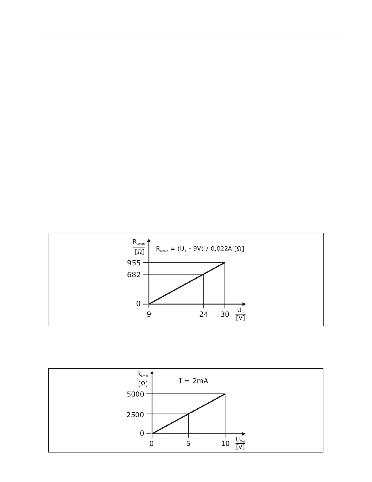
4.4 Load resistor
4.4.1 Electronic output – 2-wire, current 4…20mA
A load resistor, e.g. the measuring shunt of an evaluation device, requires a minimum supply voltage
[USmin]. Dependent on the connected supply voltage [US], it results in a maximum value for this
resistor [RLmax], where a correct function is still possible.
4.4.2 Elektronik Ausgang – 3-Draht, Spannung 0…10V
A load resistor, e.g. the measuring shunt of an evaluation device, requires at a denitive output
voltage [Uout] an output current. Due to the limitation of that output current, it results in a minimum
value for this resistor [RLmin], where a correct function is still possible.

ACS-CONTROL-SYSTEMGmbHlLauterbachstr.57lD-84307Eggenfeldenlwww.acs-controlsystem.del[email protected] 7
4.5 Connection scheme
4.5.1 Electronic output – 2-wire, current 4…20mA
Plug M12
Conductor color standard connection cable M12 – A-coded:
BN = brown, BU = blue
Plug EN 175-301-803
Cable
Conductor color cable:
RD = red, BK = black, GNYE = greenyellow
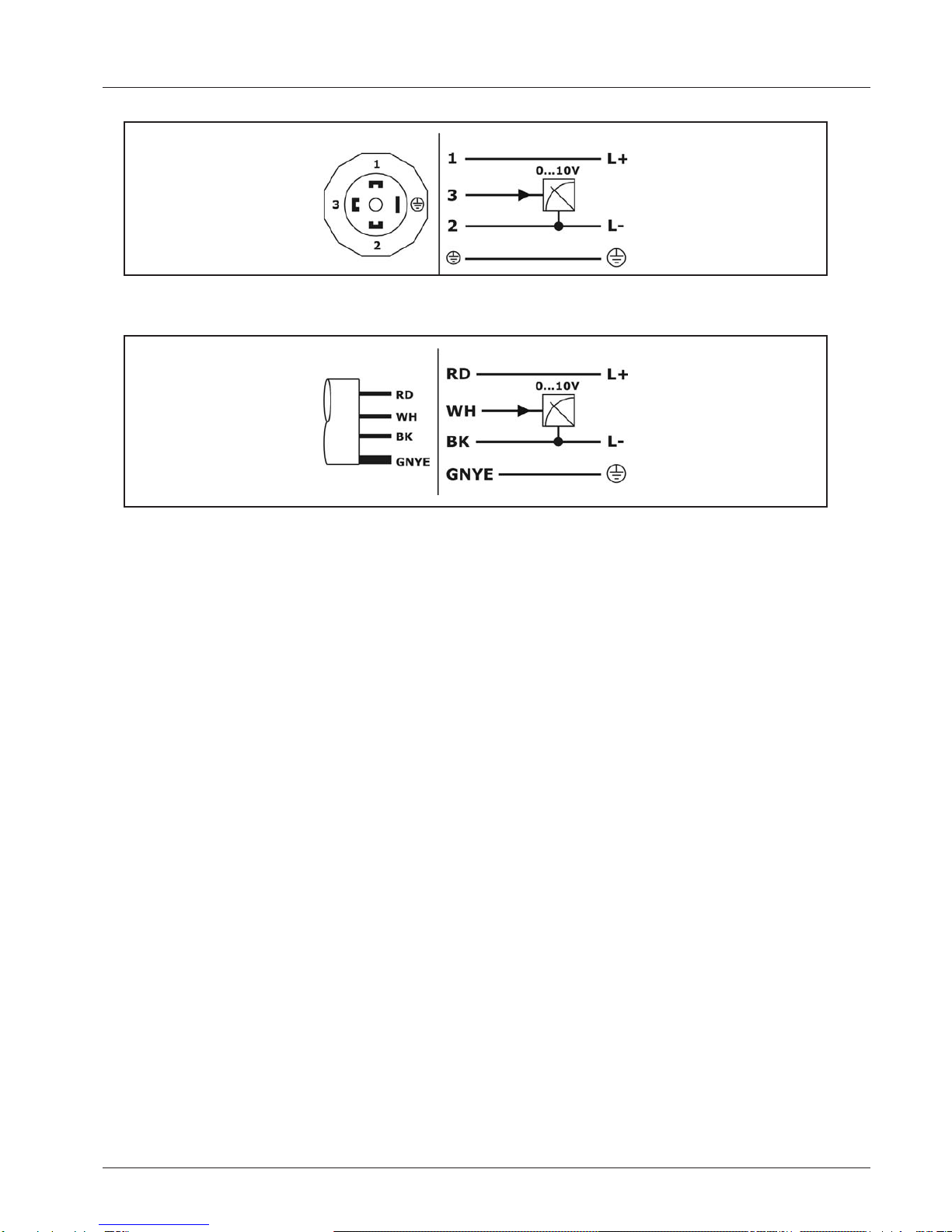
4.5.2 Electronic output – 3-wire, voltage 0…10V
Plug M12
Conductor color standard connection cable M12 – A-coded:
BN = brown, BU = blue, BK = black
ACS-CONTROL-SYSTEMGmbHlLauterbachstr.57lD-84307Eggenfeldenlwww.acs-controlsystem.del[email protected]
8
Plug EN 175-301-803
Cable
Conductor color cable:
RD = red, BK = black, WH = white, GNYE = greenyellow

ACS-CONTROL-SYSTEMGmbHlLauterbachstr.57lD-84307Eggenfeldenlwww.acs-controlsystem.del[email protected] 9
6 Service
6.1 Maintenance
The device is free of maintenance.
Special substances can lead to solid coatings on the sensor. Seized depositions can lead to faulty
measurement results.
In the case of coat forming liquids the sensor must be regularly cleaned e.g. with clear water
. Don’t
use sharp resp. hard tools or aggressive chemicals for cleaning.
6.2 Dismounting
Attention – Risk of burns!
Let the device cool down suciently fore dismounting it
During dismounting there is a risk of dangerously hot media escaping.
Attention – Risk of injury!
Dismount the device only when the system is pressureless.
During dismounting there is a risk of fast escaping media resp. pressure blow.
6.3 Repair
A repair may only be carried out by the manufacturer.
If the device is sent back for repair, the following information’s must be enclosed:
• An exact description of the application.
• The chemical and physical characteristics of the product.
• A short description of the occurred error.
6.4 Return
Before returning the device, the following measures must be performed:
• All adhesive product residues must be removed. This is especially important, if the product is
unhealthily, e.g. caustic, toxic, carcinogenic, radioactive etc.
• A returning must be refrained, if it is not possible by 100% to remove the unhealthily product
completely, because e.g. it is penetrate into cracks or is diused through plastic.
6.5 Disposal
Dispose of instrument components and packaging materials in an environmentally compatible way and
in accordance with the country-specic waste disposal regulations.
This instrument is not subject to the WEEE directive and the respective national laws. Hence, pass
the instrument directly on to a specialized recycling company and do not use the municipal collecting
points. These may be used only for privately used products according to the WEEE directive.
5 Operation
An operation provided by user is not designated.

Table of contents
Other ACS contsys Transmitter manuals


