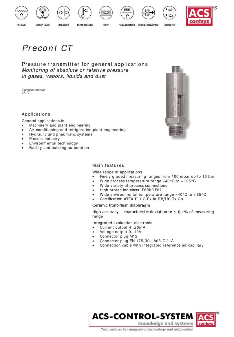
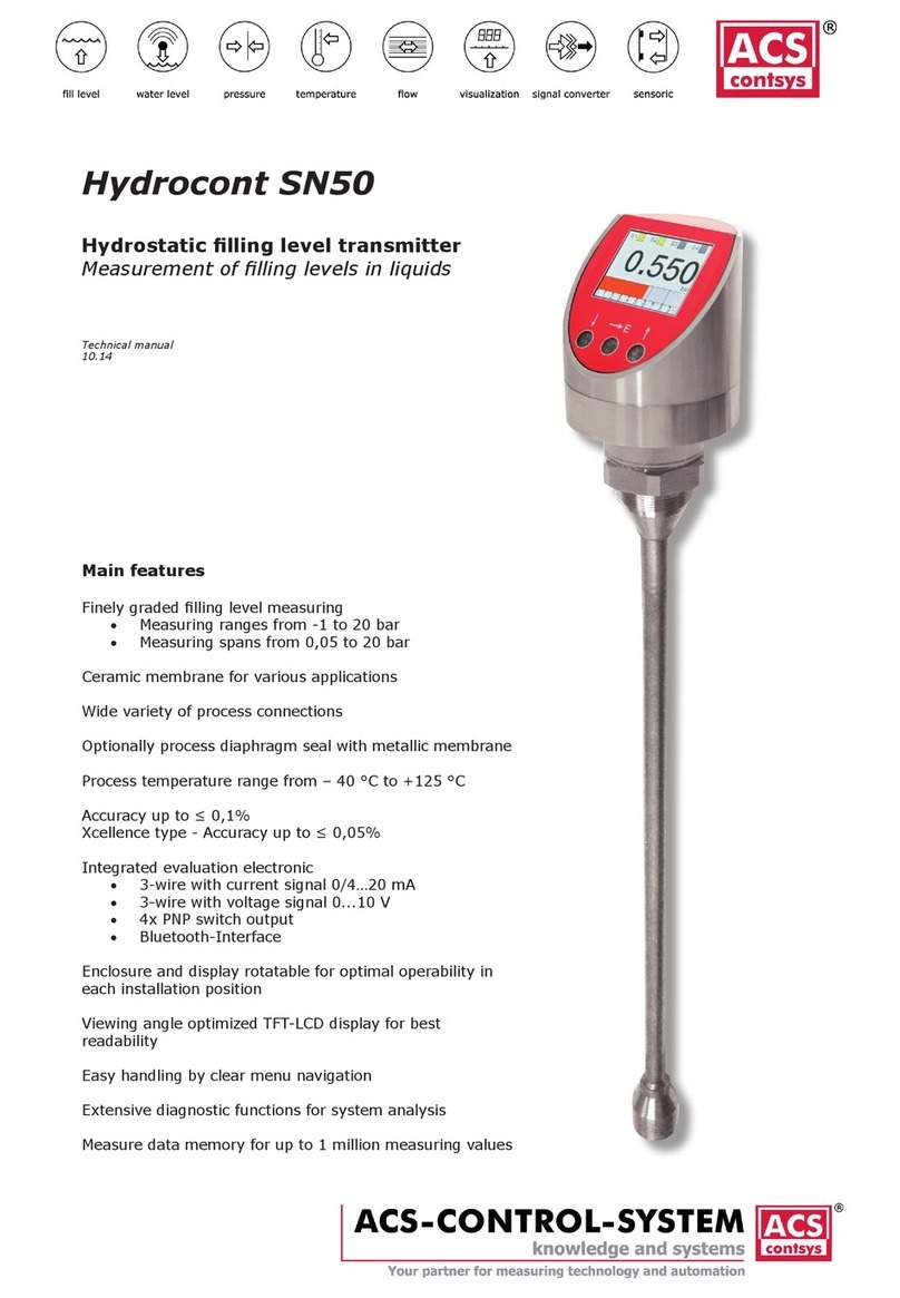
ACS contsys Sonicont USN050 User manual

11.12
Technical manual
Main features
Non-contact lling level measurement
• in liquids up to 5m
• in bulk materials up to 2m
Process temperature range from – 40 °C to +85 °C
Accuracy ≤ 0,2%
Integrated evaluation electronic
• 3-wire with current signal 0/4…20 mA
• 3-wire with voltage signal 0...10 V
• 4x PNP switch output
• Bluetooth-Interface
Enclosure and display rotatable for optimal operability in
each installation position
Viewing angle optimized TFT-LCD display for best
readability
Easy handling by clear menu navigation
Extensive diagnostic functions for system analysis
Measure data memory for up to 1 million measuring values
Sonicont USN050
Ultrasonic lling level transmitter
Non-contact measurement of lling levels
in liquids, pastes and coarse bulk materials

ACS-CONTROL-SYSTEM GmbH l Lauterbachstr. 57 l D-84307 Eggenfelden l www.acs-controlsystem.de l [email protected]
2
You have purchased a high-grade and modern measuring device of ACS-CONTROL-SYSTEM GmbH.
We want to give thanks for your purchase and for your condence to us.
The actual technical manual includes instructions for installation, electrical connection and inauguration,
as well as the technical data of the device.
Modications, that answer the purpose of the technical progress, are reserved by
ACS-CONTROL-SYSTEM GmbH without prior notice.
If a question occurs, that can‘t be answered by the listed informations, please call on our technicians
team in Eggenfelden Tel: +49 8721/ 9668-0 or [email protected]
All rights reserved

ACS-CONTROL-SYSTEM GmbH l Lauterbachstr. 57 l D-84307 Eggenfelden l www.acs-controlsystem.de l [email protected] 3
Index
Application 4
Function 4
Safety notes 5
Installation6
Installation notes 6
Installation place 8
Electrical connection 10
Potential equalization - earthing 10
Connection cable 10
Supply voltage 10
Load resistor 10
Switch output 11
Connection scheme 12
Operation 13
Operation and display parts 13
Function scheme 14
Menu structure 15
Navigation 15
Output 16
Basic Setting 20
Display 25
Simulation – extended menu structure 30
Diagnose 31
Data 33
Start-up procedure 36
Maintenance39
Repair39
Technical Data 40
Auxiliary power supply 40
Output Signal 0…20mA 40
Output Signal 4…20mA 40
Output Signal 0…10V 40
Output Switch output 40
Output Bluetooth-Interface 40
Input 41
Measuring accuracy 41
Process conditions 41
Environmental conditions 42
Materials - process wetted 42
Materials - not process wetted 42
Dimension drawings43
Terminal enclosure 43
Process connection 43
Order Code 44

ACS-CONTROL-SYSTEM GmbH l Lauterbachstr. 57 l D-84307 Eggenfelden l www.acs-controlsystem.de l [email protected]
4
Application
The device is a non-contact electronic ultrasonic lling level transmitter for continuous measuring of
lling levels in liquids, pastes and coarse bulk materials.
The use of a non-contact operating measuring systems opens a broad range of application possibilities
like e.g. at aggressive process materials.
Function
The transducer of the ultrasonic sensor transmits ultrasonic pulses to the product surface.
These pulses are reected by product surface and received back by the transducer as echoes.
The running time of the ultrasonic pulses from emission to reception is proportional to the distance
and hence the level.
The determined level is converted into an appropriate output signal and outputted as measured value.
An integrated temperature sensor compensates changes in the velocity of sound caused by
temperature changes.
The interference echo suppression function ensures that interference echoes (e.g. from edges,
welded joints and installations) are not interpreted as a level signal.
The measuring value is diagrammed at the display, whereby it can be selected between different
display styles (digital value / manometer / chart / bar graph).
In the internal ring memory up to 1 million measuring values can be recorded durable.
The measuring value can be converted into a continuous current signal 0/4...20 mA resp. voltage
signal 0...10 V or monitored by four PNP switch outputs for exceedance of limit values.
By the use of the Bluetooth interface records measuring values can be downloaded. Moreover the
conguration data can be downloaded or uploaded. This allows a fast and simple conguration of
multiple devices with the same preferences.
Additional functions can be realized on request:
• Real-time-clock for storing of the measuring values with time signature (data logger)
• Communication interface RS485 (different protocols, e.g. Modbus)
• Communication interface USB (Slave)
• Communication interface UART

ACS-CONTROL-SYSTEM GmbH l Lauterbachstr. 57 l D-84307 Eggenfelden l www.acs-controlsystem.de l [email protected] 5
Safety notes
Each person that is engaged with inauguration and operation of this device, must have read and
understood this technical manual and especially the safety notes.
Installation, electrical connection, inauguration and operation of the device must be made by a
qualied employee according to the informations in this technical manual and the relevant standards
and rules.
The device may only be used within the permitted operation limits that are listed in this technical
manual.
Every use besides these limits as agreed can lead to serious dangers.
The materials of the device must be chosen resp. checked for compatibility with the respective
application requirements (contacting materials, process temperature). An unsuitable material can lead
to damage, abnormal behavior or destruction of the device and to the resulting dangers.
The sensors may not be used as sole device for prevention of dangerous conditions in machines and
plants.
This measuring device meets article 3 (3) of the EC directive 97/23/EC (pressure equipment device
directive) and is designed and produced in good engineer practice.
The device meets the legal requirements of all relevant EC directives.
Using the device in a manner that does not fall within the scope of its intended use, disregarding
this instruction, using under-qualied personnel, or making unauthorized alterations releases the
manufacturer from liability for any resulting damage. This renders the manufacturer‘s warranty null
and void.

ACS-CONTROL-SYSTEM GmbH l Lauterbachstr. 57 l D-84307 Eggenfelden l www.acs-controlsystem.de l [email protected]
6
Installation
The correct function of the device within the specic technical data can only be guaranteed, if
the permitted process and environmental temperatures (see chapter „Technical data“) will not be
exceeded.
Installation notes
Drive the system pressure free prior installation resp. deinstallation of the sensor.
The screw-in of the thread process connection by using the terminal housing, the connection plug
resp. the connection cable is not permitted.
The tightening of the thread process connection may only be done at the hexagon by a suitable
spanner and with the maximum permitted torque strength.
The maximum permitted torque strength is 50 Nm.
The housing can be rotated every time, also at operation, mechanically by 330°.
The display can be rotated every time electrically by 180°.
Pressure / vacuum
Gauge pressure in the vessel does not inuence the measuring result. Low pressure or vacuum does,
however, damp the ultrasonic pulses. This inuences the measuring result, particularly if the level is
very low (≤ -0,2 bar resp. -20 kPa).
Vapor pressure
The vapor pressure at 20 °C (68 °F) gives a hint on the accuracy of the ultrasonic level measurement.
If the vapor pressure at 20 °C (68 °F) is below 50 mbar, ultrasonic level measurement is possible with
a very high accuracy. This is valid for water, aqueous solutions, water-solid-solutions, dilute acids (e.g.
hydrochloric acid, sulfuric acid), dilute bases (e.g. caustic soda), oils, greases, slurries, pastes, etc.
High vapor pressures or outgassing media (e.g. ethanol, acetone, ammonia) can inuence the
accuracy.
Range
The sensor range is dependent on the measuring conditions.
The maximum range can be found in the chapter “Technical Data - Input”.
Blocking distance
Install the device at a height so that the blocking distance BD (see chapter “Technical Data - Input”) is
not undershot, even at maximum ll level.
If the blocking distance is undershot, it may cause device malfunction.
If the medium reaches the transducer, buildup can form on it and cause faulty measurements later on.

ACS-CONTROL-SYSTEM GmbH l Lauterbachstr. 57 l D-84307 Eggenfelden l www.acs-controlsystem.de l [email protected] 7
Nozzle installation
Use a pipe nozzle if you cannot maintain the blocking distance in any other way.
The interior of the nozzle must be smooth and may not contain any edges or welded joints. In
particular, there should be no burr on the inside of the tank side nozzle end.
Note the specied limits for nozzle diameter and length.
To minimize disturbing factors, we recommend an angled socket edge (ideally 45°).
Nozzle diameter D Maximum nozzle length L
DN50 / 2“ 80 mm
DN80 / 3“ 240 mm
DN100 / 4“ 300 mm
≥ DN150 / 6“ 400 mm
Standpipe measurement
By using a standpipe (surge or bypass tube), the inuence of vessel installations, foam generation and
turbulence is excluded.
Standpipes must extend all the way down to the requested min. level, as measurement is only
possible within the tube.
The pipe must be provided with a sufcient venting hole (A) (Ø 5…10mm) at the upper edge.
Avoid large gaps and thick welding joints when connecting the tubes.
Measurement in a standpipe is not recommended for very adhesive products.

ACS-CONTROL-SYSTEM GmbH l Lauterbachstr. 57 l D-84307 Eggenfelden l www.acs-controlsystem.de l [email protected]
8
Installation place
Level measurement
• Do not install the sensor in the middle of the tank (C). We recommend leaving a distance
between the sensor and the tank wall (A) measuring 1/6 of the tank diameter. In vessels with
conical bottom it can be advantageous to mount the sensor in the center of the vessel, as
measurement is then possible down to the lowest point of the vessel bottom.
• Use a protective cover, in order to protect the device from direct sun or rain (B).
• Avoid measurements through the lling curtain (D). Through the action of lling, stirring and
other processes in the vessel, dense foams which considerably damp the emitted signals may
form on the product surface. If foams are causing measurement errors, the sensor should be
used in a standpipe.
• If there are strong air currents in the vessel, e.g. due to strong winds in outdoor installations
or air turbulence, e.g. by cyclone extraction, the device should be mount in a standpipe.
• Make sure that equipment (E) such as limit switches, temperature sensors, etc. are not
located within the emitting angle α. In particular, symmetrical equipment (F) such as heating
coils, bafes etc. can inuence measurement. If large vessel installations such as struts or
supports cause false echoes, these can be attenuated through supplementary measures.
Small, inclined sheet metal or plastic bafes above the installations scatter the ultrasonic
signals and avoid direct false echoes.
• Align the sensor so that it is vertical to the product surface (G).
• Never install two ultrasonic measuring devices in a tank, as the two signals may affect each
other.
• To estimate the detection range, use the 3 dB emitting angle α, that can be found in the
chapter „Technical Data - Input“. This radius of the detection range at an arbitrary distance Lx
can be calculated by the following term: rx = tan (α / 2) * Lx
Example values for Lx and rx can be found in the chapter “Technical Data - Input”.

ACS-CONTROL-SYSTEM GmbH l Lauterbachstr. 57 l D-84307 Eggenfelden l www.acs-controlsystem.de l [email protected] 9
Installation in narrow shafts
In narrow shafts with strong interference echoes, we recommend using a stand pipe resp. an
ultrasound guide pipe (e.g. PE or PVC wastewater pipe) with a minimum diameter of 100 mm.
Make sure that the pipe is not soiled by accumulated dirt. If necessary, clean the pipe at regular
intervals.
The pipe must be provided with a sufcient venting hole (A) (Ø 5…10mm) at the upper edge.
Flow measurement
• Install the device at the inow side, as close above the maximum water level Hmax as possible
(take into account the blocking distance BD).
• Position the device in the middle of the channel or weir.
• Align the sensor membrane parallel to the water surface.
• Keep to the installation distance of the channel or weir.
Example: Triangular weir

ACS-CONTROL-SYSTEM GmbH l Lauterbachstr. 57 l D-84307 Eggenfelden l www.acs-controlsystem.de l [email protected]
10
Electrical connection
The electrical connection of the device must be carried out according to the respective country specic
standards.
Incorrect installation or adjustment could cause applicationally conditioned risks.
Potential equalization - earthing
The device must be grounded.
The metallic parts of the device are electrically connected with the socket of the plug M12.
Connection cable
Use only shielded signal and measurement wires and install these wires separated from power leading
wires.
Connect the cable shield of a connected cable only at one side to earth, ideally at the installation place
of the device.
Supply voltage
The voltage applied to the terminal contacts may not exceed the maximum permitted supply voltage
to avoid damage of the electronic.
The maximum permitted supply voltage range at the respective setting is:
Signal 0/4…20mA 9…33VDC
Signal 0…10V 14…35VDC
All connections are reverse polarity protected.
Load resistor
Signal 4…20 mA
A load resistor, e.g. the measuring shunt of an evaluation device, requires a minimum supply voltage.
Dependent on the connected supply voltage, it results in a maximum value for this resistor, where a
correct function is still possible.
This resistor can be calculated by the following term:
RLmax = (US - 7 V) / 20mA
RLmax = maximum load resistor
US = connected supply voltage
Load resistor characteristic

ACS-CONTROL-SYSTEM GmbH l Lauterbachstr. 57 l D-84307 Eggenfelden l www.acs-controlsystem.de l [email protected] 11
Signal 0…10 V
A load resistor, e.g. the measuring shunt of an evaluation device, requires at a denitive output
voltage an output current. Due to the limitation of that output current, it results in a minimum value
for this resistor, where a correct function is still possible.
This resistor can be calculated by the following term:
RLmin = UOut / 3mA
RLmin = minimum load resistor
UOut = output voltage
Load resistor characteristic
Switch output
Inductive loads at the pnp switching outputs, e.g. relays or contactors may only be used with a free-
wheeling diode or a RC protection circuit to avoid high voltage peaks.
The load at the PNP switching output will be connected to the terminal +terminal of the supply voltage
by a semiconductor switch contactless and by this bounce-free.
At an activated switching state a positive signal near supply voltage is feed to the output.
At deactivated switching state and at failure of supply voltage the semiconductor switch is shut off.
The PNP switching output is current limited to 0,2...0,25 A and is overload and short circuit protected.

ACS-CONTROL-SYSTEM GmbH l Lauterbachstr. 57 l D-84307 Eggenfelden l www.acs-controlsystem.de l [email protected]
12
Connection scheme
Signal 0/4…20 mA / 0…10 V
Conductor color standard connection cable M12:
BN = brown, WH = white, BU = blue
The connection cable in not enclosed in the delivery contents.
Signal 0/4…20 mA / 0…10 V / 2x PNP switch output
Conductor color standard connection cable M12:
BN = brown, WH = white, BU = blue, BK = black, GY = grey
The connection cable in not enclosed in the delivery contents.
Signal 0/4…20 mA / 0…10 V / 4x PNP switch output
Conductor color standard connection cable M12:
WH = white, BN = brown, GN = green, YE = yellow, GY = grey, PK = pink, BU = blue, RD = red
The connection cable in not enclosed in the delivery contents.

ACS-CONTROL-SYSTEM GmbH l Lauterbachstr. 57 l D-84307 Eggenfelden l www.acs-controlsystem.de l [email protected] 13
Operation
Operation and display parts
A – LCD display
• Display of measuring value, device state and operation menu
B - Key Down
• In the selection menu navigation downwards
• In the set menu decreasing of value
• Used, in combination with the key up, for leaving selection and set menu without applying
changings
• Used, in combination with the key up, for a step backwards one menu item
C - Key Enter/Shift right
• Access to operation menu
• In the selection menu entering the selected sub menu
• In the set menu applying the new value and digit shift right
D - Key Up
• In the selection menu navigation upwards
• In the set menu increasing of value
• Used, in combination with the key down, for leaving selection and set menu without applying
changings
• Used, in combination with the key down, for a step backwards one menu item

ACS-CONTROL-SYSTEM GmbH l Lauterbachstr. 57 l D-84307 Eggenfelden l www.acs-controlsystem.de l [email protected]
14
Function scheme
A - Commissioning
B - Vessel type
C - Noise lter
D - Pulse rate
E - Limit min/max
F - Echo loss
G - Damping
H - Min/Max Adjustment > e.g. 1,8..0,4 m = 0..100 %
I1 - Linearization > Level - display scaling e.g. 0,4..1,8 m = 0..2000 m3
I2 - Linearization > Percent 0..100 % - Lin. Percent 0..100 %
I3 - No linearization
J - Signal output > e.g. 0..100 % = 4..20 mA resp. 0..20 mA resp. 0..10V
K - Error signal evaluation
L1 - Switch / reset switch point S1
L2 - Switch / reset switch point S2
L3 - Switch / reset switch point S3
L4 - Switch / reset switch point S4
M1 - Error indication function S1
M2 - Error indication function S2
M3 - Error indication function S3
M4 - Error indication function S4
N1 - Display scaling > Distance e.g. 0..100 % = 1,8..0,4 m
N2 - Display scaling > Fill level e.g. 0..100 % = 0,4..1,8 m
N3 - Display scaling > Percent 0..100 % = 0..100 %
N4 - Display scaling > scaled e.g. 0..100 % = 0..2000
N5 - Display scaling > Signal Output 0..100 % = 4..20 mA resp. 0..20 mA resp. 0..10 V
O - Display unit > at display scaling scaled e.g. m3
P - Error indication display
Q1 - Display - Distance e.g. 1,8..0,4 m
Q2 - Display - Fill level e.g. 0,4..1,8 m
Q3 - Display - Percent 0..100 %
Q4 - Display - scaled e.g. 0..2000 m3
Q5 - Display - Signal Output 4..20 mA resp. 0..20 mA resp. 0..10 V

ACS-CONTROL-SYSTEM GmbH l Lauterbachstr. 57 l D-84307 Eggenfelden l www.acs-controlsystem.de l [email protected] 15
Menu structure
The entrance to the different function areas of the selection and set menu layer is done by the main
menu (push the key Enter/Shift right for 3 seconds).
If failures are registered (see chapter diagnose/failure), these are indicated prior the jump into the
main menu.
By the key Enter/Shift right the failure indication will be canceled.
The symbol E at a menu item indicates its position in the extended menu structure.
This extended menu structure can be shown in the submenu display by the menu item menu
structure.
Submenu output
Settings for the function of the switch outputs and the signal output.
Submenu basic setting
Settings for the basic adaption of the device to the measuring task, e.g. adjustment, damping
and linearization.
Submenu display
Settings for the adaption of the measuring value indication to the measuring task, e.g. measuring
value scaling, display type, menu language and also password protection.
Submenu simulation
Settings for the simulation of the switch outputs and the signal output, e.g. for inauguration or
also for failure analysis.
Submenu diagnose
Multiple information to the historical measuring activity and the device, that can be useful for
system surveillance or also for failure analysis.
Submenu data
Settings for the measuring value recording and the data transmission by Bluetooth.
Navigation
The navigation in a submenu and in a selection window is done by the keys Up and Down.
The selection of a submenu and the selection of a setting in a selection menu is done by the key
Enter/Shift right.
The jump backward from a submenu to the higher-level menu is done by the menu item back or by
the simultaneous pushing the keys Up and Down.
The leaving of a selection menu without applying the changings is done by the simultaneous pushing
the keys Up and Down.
The input of a value or text in a set menu is done digit by digit.
For the changing of the selected digit the keys Up and Down are used.
For the changing of the digit the key Enter/Shift right is used.
The applying of a set value resp. text is done by pushing the key Enter/Shift right for 3 seconds.
The leaving of an set menu without applying a value resp. text is done by the simultaneous pushing
the keys Up and Down.
After 5 minutes of inactivity the active submenu resp. selection menu will automatically be left and a
change to the measuring value indication is executed.
A jump backward is not executed from an active set menu.

ACS-CONTROL-SYSTEM GmbH l Lauterbachstr. 57 l D-84307 Eggenfelden l www.acs-controlsystem.de l [email protected]
16
Output
The symbol E at a menu item indicates its position in the extended menu structure.
This extended menu structure can be shown in the submenu display by the menu item menu
structure.
Switch output S1 / S2 / S3 / S4
Enabled
Each switch output can be activated resp. deactivated separately.
• Yes
• No
Default > Yes
Switch Point / Reset Switch Point
The input values refers to the set display value or acc. to display scaling.
The reset switch point must be lower or equal to the switch point.
At inverse measuring principle, e.g. distance measurement, the reset switch point must be greater or
equal to the switch point.
The input range is limited to the measuring range.
Default > S1 = 20% / S2 = 40% / S3 = 60% / S4 = 80%
Switch Delay Time / Reset Switch Delay Time – extended menu structure
The activation resp. deactivation of the switch output can be biased with a delay time (resolution
0,01s), to realize simple sequence control system.
The input range is indenite.
Default > 0s

ACS-CONTROL-SYSTEM GmbH l Lauterbachstr. 57 l D-84307 Eggenfelden l www.acs-controlsystem.de l [email protected] 17
Function – extended menu structure
Hysteresis function
The hysteresis function realizes a stable switch state, independent from system conditioned signal
uctuations around the adjusted set point.
It can be used for realizing a signal controlled two-position control.
The switch range is determined by denition of switch point and reset switch point.
The switch output is activated, if the current measuring value exceeds the switch point and if the set
switch point delay time has been expired.
The switch output is deactivated, if the current measuring value exceeds the reset switch point and if
the set reset switch point delay time has been expired.
At inverse measuring principle, e.g. distance measurement, the switch output is activated, if the
current measuring value underrun the switch point and if the set switch point delay time has been
expired.
Accordingly the switch output is deactivated, if the current measuring value exceeds the reset switch
point and if the set reset switch point delay time has been expired.
Window function
The window function realizes a signal range – acceptance region –, where the switch output is set to a
denitive switch state.
The switch range is determined by denition of switch point and reset switch point.
The switch output is activated, if the current measuring value is inside the area that is dened by the
switch point and the reset switch point and if the set switch point delay time has been expired.
The switch output is deactivated, if the current measuring value is outside the area that is dened
by the switch point and the reset switch point and if the set reset switch point delay time has been
expired.
Error Indication Function
The switch output is activated, if the device has detected a failure behavior (see chapter diagnose/
failures).
Default > Hysteresis Function

ACS-CONTROL-SYSTEM GmbH l Lauterbachstr. 57 l D-84307 Eggenfelden l www.acs-controlsystem.de l [email protected]
18
Operating Mode
The operating mode denes the function direction of the switch output.
• Normal Open / NO
At the output there is no signal, if the switch condition is not fullled.
At the output there is a signal, if the switch condition is fullled.
• Normal Close / NC
At the output there is a signal, if the switch condition is not fullled.
At the output there is no signal, if the switch condition is fullled.
Default > Normal Open / NO
Signal output
The nominal values of the analogue signal (4/20 mA resp. 0/10mA resp. 0/10 V) refers to the set
display nominal values 0% and 100%
Operating Mode
Denes the type of the analogue output signal
• 4-20 mA
• 0-20 mA
• 0-10V
Default > 4-20 mA

ACS-CONTROL-SYSTEM GmbH l Lauterbachstr. 57 l D-84307 Eggenfelden l www.acs-controlsystem.de l [email protected] 19
Error Signal
Denes, dependent on the operating mode, the analogue output signal regarding operating range and
if errors (see chapter diagnose/failures) are registered.
• Operating mode 4-20mA
A - Off >> 3.9-21mA
B - 3.6mA
C - 22mA
• Operating mode 0-20mA
A - Off >> 0-21mA
B - 0mA
C - 22mA
• Operating mode 0-10V
A - Off >> 0-10,5V
B - 0V
C - 11V
Default > Off

ACS-CONTROL-SYSTEM GmbH l Lauterbachstr. 57 l D-84307 Eggenfelden l www.acs-controlsystem.de l [email protected]
20
Invert Signal
Inverts, dependent on the operating mode, the analogue output signal.
• 4-20 mA >> 20-4 mA
• 0-20 mA >> 20-0 mA
• 0-10 V >> 10-0 V
Default > No
Basic Setting
The symbol E at a menu item indicates its position in the extended menu structure.
This extended menu structure can be shown in the submenu display by the menu item menu
structure.
Commissioning
The commissioning function can be used to adapt the device to the constructive conditions.
Therefore the device must be operated in it’s nally installed position at the lowest possible known
lling level.
After setting the vessel type the detected measuring value must be conrmed or possibly corrected.
Afterwards the detection of the envelope curve for the error echo suppression is processed.
Error echoes causing installations, positioned below the lling level when processing the
commissioning function, cannot be detected.
Table of contents
Other ACS contsys Transmitter manuals
Popular Transmitter manuals by other brands
SAC
SAC SE SERIES Installation and setup manual
Becker
Becker B-Tronic VarioControl VC3201B Assembly and operation instructions
EUTECH INSTRUMENTS
EUTECH INSTRUMENTS ALPHA PH 500 PHORP 2-WIRE TRANSMITTER (REVISION... instruction manual
PRASTEL
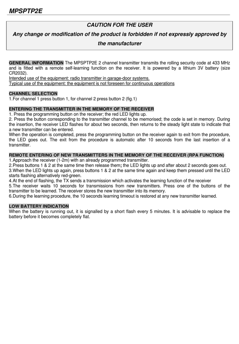
PRASTEL MPSPTP2E manual
Wireless Devices
Wireless Devices M-823 Operation manual
Telex
Telex PST-170 operating instructions
