Actall ATLAS User manual

ATLAS | Crisis Controller User Manual
Version 5.06
www.actall.com

Copyright © 2018 Actall Corporation | www.actall.com
2
©Copyright 2018by Actall Corporation®. All rights reserved. Crisis
Controller©™ is a registered trademark of Actall Corporation. (U.S.
Patent No.: 5,708,417) MicrosoftP®P and WindowsP®P are registered
trademarks of MicrosoftP®P Corporation. Crisis Controller©™P Version
5.00 software and documentation developed by Actall Corporation®,
Denver, Colorado. (TUwww.actall.comUT) This manual is subject to
change and may not be reproduced in any way or form, electronic or
mechanical.
Software License Agreement:
The use of this software product is limited to the terms and conditions
below. Use by the purchaser of Crisis Controller©™ Alarm Monitoring
software indicates acceptance of these terms.
Grant of Rights:
This software may only be used on the computers for which it is licensed.
This license may not be transferred from its original site. You may not
copy or otherwise distribute this software, except to make a backup
copy. You may not modify, alter, or transfer the software in any way.
Limitation of Liability:
Licensor shall not be liable for any claim or demand by Licensee for
damages of any kind, including, but not limited to special, general,
incidental, direct or consequential dam-ages, for loss of business
prots, business interruption, loss of business information, or any other
pecuniary loss arising out of the subject matter of this agreement Some
jurisdictions do not allow excluding or limiting implied warranties or
limiting liability or consequential damages, and some jurisdictions have
special statutory consumer protection provisions that may supersede
this limitation. As a result, this limitation of liability may not apply to you
if prohibited by the laws of your jurisdiction.
General:
Any violation of this Agreement is subject to criminal and civil prosecution.
If any provision is found to be unlawful, void, or unenforceable, then that
provision shall be severed from this Agreement and will not aect the
validity and enforceability of any of the remaining provisions. The laws of
the State of Colorado shall govern this Agreement.
COPYRIGHT & LIMITATIONS CONTACT
Inquiries should be
directed to:
Actall Corporation
2017 Curtis St.
Denver, CO 80205
Phone:
303-226-4799
Toll-free:
1-800-598-1745
For technical support,
please call us direct
during regular
business hours
(Monday through
Friday, 8:00 a.m. to
5:00 p.m. Mountain
Standard Time) or
Emai us 24/7.
303-226-4799

3
Crisis Controller—ATLAS System User Manual
SOFTWARE REGISTRATION CARD MUST BE FILLED OUT
Actall® Technical Support needs the informaon on this card to verify authencity of requests for service and to be able to
provide mely and accurate technical assistance to our customers.
In addion, it is in the customer’s interest for Actall® to have a duplicate record of soware serial numbers and Hardware
Key codes. It also protects the customer if quesons of soware licensing arise. Addional informaon, such as computer
type, operang system, and general applicaon informaon can save a great deal of valuable me in troubleshoong and
responding to customer needs.

4
Crisis Controller Main Screen……………………………………………………………………............ 5
Aendants………………………………………………………………………………………………….......... 7
Add/Edit Aendants ……………………………………………………………………........... 8
Staons……………………………………………………………………………………………………............ 13
Data Servers……………………………………………………………………………………………….......... 14
MGEs……………………………………………………………………………………………………................ 17
Add/Edit MGE Template…………………………………………………………………......... 17
Discover MGEs…………………………………………………………………………………....... 19
Add/Edit MGEs…………………………………………………………………………………....... 20
Pager Services……………………………………………………………………………………………......... 23
Intercom Systems……………………………………………………………………………………….......... 25
Contact Input/Outputs………………………………………………………………………………........... 27
HDT (ATLAS) ......………………………………………………………………………………................... 31
HDT Profile………………………………………………………………………………………....... 32
HDT Template ……………………………………………………………………………….......... 34
Add/Edit HDT………………………………………………………………………………............ 38
HDT Programming………………………………………………………………………………………......... 41
Cricket Alarm Prole....................................................................................42
Cricket Template..........................................................................................44
Add/Edit Cricket...........................................................................................47
LDNs…………………………………………………………………………………………………………........... 48
LDN Templates…………………………………………………………………………………....... 51
Add/Edit LDNs……………………………………………………………………………………..... 55
Entering People……………………………………………………………………………………………....... 60
Guard Routes…………………………………………………………………………………………………...... 62
Maps…………………………………………………………………………………………………………........... 64
Adding a Map…………………………………………………………………………………......... 65
Map Layout..................................................................................................66
Opons/Sengs………………………………………………………………………………………............ 68
Network…………………………………………………………………………………………......... 69
Alarm Processing (FPT, HDT)………………………………………………………….......... 70
Alarm Output (Printer logging Serial I/O)……………………………………….......... 71
Locaon logging………………………………………………………………………………........ 72
Alarm Monitoring.................................................................................................... 73

5
Crisis Controller—ATLAS System User Manual
Aer logging into Crisis Controller, the Main menu opon will be available. The drop down menus are as follows:
HDT
Change the current user.
Exit the system (Actall Special user and password need to exit the
system).
Access to ATLAS transmitters, LDNs and related options.
Access to Stations, MGEs and outside hardware interfaces.
Access to HDT assignment menus.
Access to Map and Mapping functions as well as other system options.
Start and stop alarm monitoring mode.
Access to system reports.
Allows the user to arrange the open windows
Access to the Help file and Crisis Controller version information.

6
There are ve windows on the status bar that contain informaon. From le to right they are
If the Crisis Controller system is operang in as a network version, the soware will monitor the network and
database connecvity. In the event Primary database connecon fails the system will display a warning screen
stang the database is no longer found. The system will then look for the backup database (located on any computer
running Crisis Controller). If the database can not be located the system will revert to it’s local backup copy
of the database. When the fault is corrected the system can than be reconnect to the primary database.
1
2
3
If you mouse over the window the path of the database will be shown.
There are three possible database that may be shown
1) (for networked system only)
This database is the network database congured in the (Actall.CrisisController.FormsUI.exe.cong) le.
2) (for networked system only)
This database is the network backup database congured in the (Actall.CrisisController.FormsUI.exe.
cong) le.
3) (stand alone and network versions)
This database is the database congured in the (Actall.CrisisController.FormsUI.exe.cong) le.
4 C
5 C
Crisis Controller—ATLAS System User Manual

7
Crisis Controller—ATLAS System User Manual
These attendants can only assign or de-assign HDT and print reports. All other functions are inaccessible
These aendants can only do alarm monitoring. Operators can not stop Alarm Monitoring or exit the
system.
Aendants operate and control all
funcons of the Crisis Controller soware.
Users are entered into Crisis Controller at
Admin, Operator, and Supervisor levels.
Use this buon to add in a new aendant.
Use this buon to edit and excing aendant.
Use this buon to delete a aendant from the system.

8
Under alarm monitoring mode there are access rights that can be assigned.
View Status and System Message tabs
Enable and disable Transmier Groups and start and top the Guard Tour opon.
Change the Time Mode (Day, Evening and Night).
Seng this opon does not show the Acon Taken/ Notes window.
Users set at this level have full access to all system opons. They can start and stop Alarm Monitor-ing as well as
perform system conguraon.
When adding aendants the following informaon is required:
Aendants login name (ex: Sgt.Smith)
Aendants password.
(Blank password are permied)
Crisis Controller—ATLAS System User Manual

9
Crisis Controller—ATLAS System User Manual
This secon indicates to the system what right the aend will have.
These attendants can only assign or de-assign HDT and print reports. All other functions are inac-cessible.
These aendants can only do alarm monitoring. Operators can not stop Alarm Monitoring or exit the system.
Under alarm monitoring mode there are access rights that can be assigned.
Users set at this level have full access to all system options. They can start and stop Alarm Monitoring and do
system conguraon.
This secon allows you to assign rights to Monitoring mode funcons.
Allows the aendant to enable and disable Transmier Groups and start and stop the Guard Tour opon.
Allows the aendant to change the Time Mode (Day, Evening and Night).
Checking this will allow the aendant to view the FPT Status Tab.
Checking this will allow the aendant to view the System Messages Tab.
Checking this will allow the attendant to view the HDT Status Tab.
Seng this opon does not show the Acon Taken/Notes window.

10
Operators are individuals whose primary function is to monitor the ATLAS In the
event of an alarm, Operators will access system information and monitor responses. Once logged in as an
Operator, the monitoring screen cannot be minimized or exited by the Operator.
Operator-level personnel may be authorized to access various levels of informaon, as well as per-form several
selecve tasks. The degree of access is determined by opons set by a Supervisor on the
screen.
Operators respond to informaon generated by the Crisis Controller soware. Informaon about the system is
displayed on the system monitor in Windows®-based informaon screens. Incoming alarm or trouble messages
appear in the display with oponal warning sounds, congured for each device.
Operators are responsible for acknowledging incoming alarms and determining that proper re-sponses are
generated. This can include alarm vericaon and/or documentaon of incoming data, depending upon the
operang requirements of the Owner.
Crisis Controller—ATLAS System User Manual

11
Crisis Controller—ATLAS System User Manual
Supervisors have access to all features. Supervisor-level personnel can access all menus. This permits them to
congure the system and control user access levels and passwords.
Supervisors create and assign passwords to Operator and Admin users.
Supervisors may add or delete Transmiers, Receivers, Repeaters, RF locators and any other hard-ware from the
system.
Only Supervisors with an Actall generated special user and password can exit the system once it has been
acvated.
System Supervisors have access to data that is not available to Operators or Administrave Users. For example,
the Supervisor is authorized to access and modify account data informaon, and to review and modify
informaon regarding system hardware.
Supervisors can import and edit site maps. Supervisors can set Transmier programming, including how the
system will respond to each Transmier.
These menus include crical Supervisor responsibilies. Hardware and account informaon is man-aged through
features used to congure the system. Supervisors may nd it helpful to remember that most program funcons
of the Crisis Controller soware are designed to present them rst with a drop-down list of informaon. From
the list, Supervisors may make selecons that acvate programming or data forms that can modify informaon
in the list. This drop-down list architecture is followed in all features of the program, and is parcularly pernent
to conguraon tasks.

12
The Crisis Controller logon window allows you to change the current Aendant using the system.
In order to login to the Crisis Controller system you will need a user name and password. These are setup by
aendants with Supervisor rights (see the tools secon on page xxx)
To logon to the system choose tool > logon and the above screen will be shown. Enter in your aen-dant name
and password. EXAMPLE:
NAME Operator
1234
Crisis Controller—ATLAS System User Manual

13
Crisis Controller—ATLAS System User Manual
The Device tab in Crisis Controller is reserved for creating and editing Stations, Data Servers and
Gateways (MGEs). These devices form the primary interface between field devices (HDTs and LDNs) and
the Crisis Controller software.
Upon startup, the informaon pre-congured onto your security key will display in the Staon main screen.
When conguring a Staon, you must rst select the appropriate staon from the drop down list and enter the
following informaon:
Pick a property code (1-32) to uniquely idenfy
this system. The default value will be 1.
Addional property codes can be added to this staon
from this screen. In addion, other property codes used
on this site can be ig- nored for this staon by checking
the box under Opons.

14
Data Servers are used to aggregate and process locaon and alarm informaon transmied from MGEs.
Name the Data Server (60 Char MAX.
Alpha Numeric and special characters
are OK)
Select the Staon that this Data Server
is providing locaon informaon to.
All MGEs detected by this Data Server
will be displayed.
Crisis Controller—ATLAS System User Manual

15
Crisis Controller—ATLAS System User Manual
Type in the IP address of the monitoring staon.
The IP address is pre- programmed from Actall and
can be found in the system documentaon
accompanying your CPU. Alternavely, the IP address
can be looked up using the ipcong command in
the Windows Command Line Ulity.
When the appropriate entries have been entered correctly, click the OK box to close the window for this Staon and
the Close box to close the Main Staon dialogue box.

16
If this Data Server is to be used as the Primary Data Server (in mulple server conguraons), check the ‘Enable’
box. If this is a conguraon using only one Data Server, then this box should be checked.
On smaller installaons that are installing the Data Server and running Crisis Controller on a single CPU, the ‘Use
Host Monitor Staon’ box should be checked. Larger PALS Atlas installaons will use separate pieces of
hardware to process data and run Crisis Controller.
If a separate piece of hardware is used for the Data Server, the IP address (or DNS name) of the Data server must
be entered in the IP/DNS box. The Port box is precongured as PORT 1024; other ports may be used.
If the Data Server being congured is used as a backup, then the Backup Server box should be checked. The same
conguraon instrucons as used above should be changed for this selecon.
The Check in interval for both HDTs and LDNs should be established here. The default value for both types of
devices is 100 seconds, congurable in 10 second increments to a maximum of 2550 seconds. The LDN Buer
Window establishes the minimum mes that LDNs will transmit back to MGEs. The default value is 1 second,
congurable in one second increments up to 25.5 seconds.
Crisis Controller—ATLAS System User Manual

17
Crisis Controller—ATLAS System User Manual
MGE Templates are used to pre-populate conguraon sengs for MGEs. Informaon loaded to MGEs via the
template menu can be individually altered for each MGE, if needed. Exisng tem-plates will be displayed upon
window launch, if no templates are displayed, click on the ADD buon to enter new informaon.
When adding an MGE Template, the following
sengs must be entered:

18
Select the name of the system to idenfy this Template.
Choose from the available Data Servers already congured.
Unique Idener for the RF devices deployed in this system.
RF Channel (900 mHz) used for communicaon between devices in the system.
Once deployed, all devices will renegoate their chan- nel based upon
their locaon and network availability.
Default value for RF communicaon power. Do not change without
consulng Actall technical personnel.
These values will be communicated to the
led devices when the devices con-nect to that MGE.
This sets the delay that the PMT will experience (with warning tones) once a
man down condion is experienced. The default value is 5 seconds, available
values are 1—255 seconds.
This value sets the interval that the PMT locaon radio will broad cast its ID for
read by LDNs. The default value is 0.5 seconds, avail able values are 0.5 to
25 seconds.
Reserved for future use.
Crisis Controller—ATLAS System User Manual

19
Crisis Controller—ATLAS System User Manual
This Tab sets the RF properes of the eld
deployed eld devices.
Link Quality Indicator. This value sets the minimum strength at which an MGE will
connue to connect to a eld device. The de- fault value is 55; a range of values between
1 and 255 is possible. A value of 75 or higher is recommended.
Select three channels for device communicaons on the 2400 MHz channel. These
channels will need to modied in the MGE edit screens, based upon the results of the RF
survey.
This value will set the signal strength for PMT communicaons on the 2.4 channel. The
default value is 7, possible values can be 0— 15. The default value should not be
changed unless recommended by the R F survey.

20
When the Discovering MGEs screen is launched, all Gateways reporng to this staon will be displayed. Individual
devices may then be edited by double clicking on the appropriate device.
Crisis Controller—ATLAS System User Manual
Table of contents
Other Actall Controllers manuals
Popular Controllers manuals by other brands

Kyocera
Kyocera SCS-IV datasheet
Emerson
Emerson Bettis Multiport Installation, operation and maintenance manual
BIFFI
BIFFI HLAS Use and maintenance manual
Munters
Munters TRIO User and installation manual
Murphy
Murphy EMS PRO Installation and operation manual
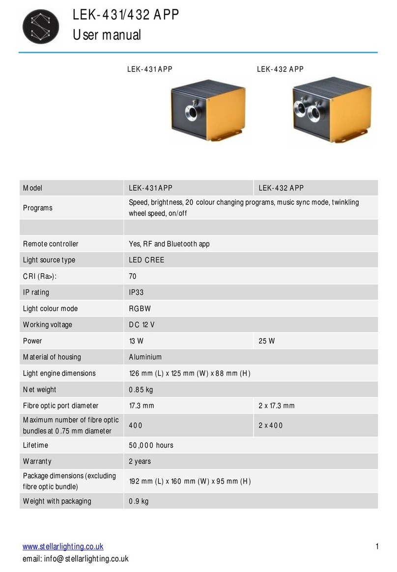
Stellar Lighting
Stellar Lighting LEK-431 APP user manual

Aficio
Aficio AP1015 operating instructions
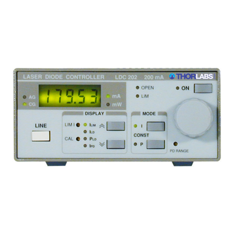
THORLABS
THORLABS Blueline Series Operation manual

AGS
AGS Merlin 1000S+i User & installation manual
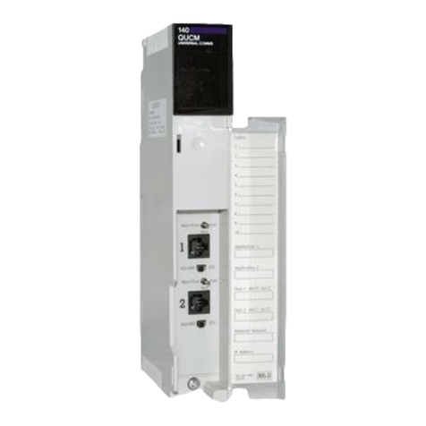
Niobrara
Niobrara QUCM Installation and programming manual

Mercoid
Mercoid Series MPC Specifications-installation and operating instructions

Parker
Parker R34 Installation & service instructions

