Pub 49442
Effective 01/02 3
Overload Protection with
Mechanical Starter
Overload protection of the
motor is easil
achieved b
installin
a mechanical starter
on the suppl
side of the soft
start controller.
The overload provides the
necessar
motor protection for
an overload condition.
A short circuit protective
device is required to meet UL
requirements.
*Use UL specified backup
fuse.
Specifications
Table 1. Thermal Specifications
Table 2. Insulation Specifications
Current Deratin
Current Derating in High Temperature Applications
Operation in ambient temperatures exceedin
40°C is possible
if the power dissipation is limited either b
reducin
the stead
-
state current or b
reducin
the dut
c
cle of the soft starter as
shown in Table 3.
Table 3. Temperature Specifications
Table 4. Current Derating by Trip Class
EMC
This compartment meets the requirements of the product stan-
dard EN60947-4-2 and is CE marked accordin
to this standard.
Table 5. Output Specifications —Main Circuit
Table 6. Control Specifications
Product Selection
Table 7. Product Description and Item Selection
Short Circuit Protection
Two t
pes of short circuit protection can be used:
short circuit protection b
circuit breaker
short circuit protection b
fuses
Short circuit protection is divided into two levels —
T
pe 1 and T
pe 2.
T
pe 1 —protects the installation
T
pe 2 —protects the installation and the
semiconductors inside the motor controller
Short Circuit Protection by Circuit Breaker
A 3-phase motor with a correctl
installed and adjusted over-
load rela
will not short-circuit totall
to earth or between the 3
phases. Part of the windin
will normall
limit the short circuit
current to a value that will cause instantaneous ma
netic trip-
pin
of the circuit breaker without dama
e to the soft starter.
The ma
netic trip response current is approximatel
11 times
the maximum adjustable current.
Description Specification
Power dissipation for continuous
operation PD max.
2 W/A
Power dissipation for intermittent
operation PD
2 W/A x duty cycle
Cooling Method Natural convection
Mounting (No Derating) Vertical ±30°
Operating temperature range,
EN60947-4-2 (no derating)
-5°to 40°C*
[23°to 104°F]
* UL Tested.
Storage temperature, EN60947-4-2 -20°to 80°C
[-4°to 176°F]
Max. operating temperature with current
derating according to table
60°C [140°F]
Description Specification
Rated insulation voltage Ui 660 Volt
Rated impulse withstand voltage Uimp 4 kVolt
Installation category III
Ambient Temperature S701X25N3BP
50°C [122°F] 20A continuous
Limited Duty Cycle Rating by 50°C On-time max. 15 min.
Duty cycle max. 0.8
60°C [140°F] 17A continuous
Limited Duty Cycle Rating by 60°C On-time max. 15 min.
Duty cycle max. 0.65
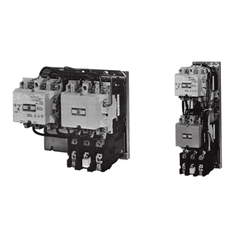
Figure 9. Overload Protection
with Mechanical Starter *
Overload
Trip Class
Without
Bypass
With
Bypass
10A
10
20
30
25A
25A
20A
15A
30A
30A
24A
19.5A
Approvals: UL Std. No. 508
Environment: Degree of Protection / Pollution Degree: IP20 / 3
Description Specification
Short circuit protecting fuse (max.) 80 A gL/gG. No time delay
Operational current (max.) 25A AC-53a, 30A AC-53b
Semiconductor protecting fuse (max.) 6300 A2S
Overload relay trip class 10 or 10A
Description Specification
Control voltage range 24 –300V AC/DC
Control current/power (max.) 15 mA/2 VA
Ramp-Up time Adjustable from 0.5 to 20 sec.
Ramp-Down time Adjustable from 0.5 to 20 sec.
Initial torque Adjustable from 0 to 85% of nominal
torque with optional Kick Start
Output/Current voltage (max.) 0.5A AC14, AC15,
24 –480V AC 50 –60 Hz
Fuse (max.) 10 A gL/gG. l2t max. 72 A2S
Line
Voltage
(V AC)
Motor
Size w/o
Bypass
Motor w/
Bypass
Control
Voltage
Range*
* 24 –480V for CE only.
Controller
Type
Designationhp / kW hp / kW AC/DC
208 –230 10 / 7.5 10 / 7.5 24 –300V S701C25N3BP
400 –480 15 / 11 20 / 15 24 –300V S701E25N3BP
550 –600 20 / 15 25 / 18 24 –300V S701G25N3BP
