Action Trackchair EAGLE User manual
Owner’s Manual
Action Trackchair
FALCON
FDA Cleared # K163451
Action Trackchair
EAGLE
FDA Cleared # K181908
Action Trackchair
HAWK
FDA Cleared # K202728

Action Trackchair/Trackstander Owner’s Manual
This manual is appropriate for the following models
Models (Action Trackchair Eagle) Models (Trackstander Falcon)
Model 16, 18, 20, 22, and 24 Model 1816, 1820, 2016, 2020
Models (Action Trackchair Hawk)
Model 14, 16, 18, 20, and 22
Updated May 2022
Page | 1

Page | 2
Table of Contents
Action Manufacturing
1105 Lake Road
Marshall, MN 56258
507-532-5940
www.actiontrackchair.com
Table of Contents…...................................................................................................................................
2
Introduction and Indication For Use.........................................................................................................3
Safety ....................................................................................................................................................4/5
Label Locations… .................................................................................................................................. 5/6
Device Description and Proposed Conditions of Use forthe Trackstander..............................................7
Device Description and Proposed Conditions of Use forthe Trackchair ..................................................7
Operating the Action
Trackchair/Trackstander
..........................................................................................8
Comfort Adjustments...............................................................................................................................9
Transferring into the Trackstander.........................................................................................10/11/12/13
Batteries and Charging.................................................................................... 13/14/15/16/17/18/19/20
Repair and Maintenance ........................................................................................................................ 21
Cleaning Your Trackchair and Trackstander ............................................................................................21
Warranties..............................................................................................................................................21
EMC Compliance ................................................................................................................22,23,24,25,26
Disclosure, Documentation and Labeling................................................................................................
27
Specifications and minimum braking .....................................................................................................28
Dimensional Information........................................................................................................................
29
Summary of testing data ................................................................................................. 30/31/32/33/34
Table 1: Hand Control Fault & Warning Indicators........................................................................... 35,36
Strapping Methods with Trackchair/Trackstander Carrier.....................................................................37
Rocker Switch Override Instructions ......................................................................................................38
Sit to Stand FunctionOverride Instructions........................................................................................... 39
Law, Regulation and Policy for Wheelchair/Mobility Device Use “Federally Designated Wilderness. 40
Pro Charging Dual Pro Battery Charger Manual… .............................................................................41/48

Page | 3
Introduction
Welcome to Action Manufacturing, we want to make your experience the best it can be. Enclosed in this
owner’s manual, you’ll find information to use and maintain your Action Trackchair Eagle, Action Trackchair
Hawk, and the Action Trackstander Falcon models.
With any questions please contact us at:
Action Manufacturing
1105 Lake Road
Marshall, MN 56258
507-532-5940
info@actionmfginc.com
Indication for use Action Trackstander Falcon
The Action Trackstander Falcon all-terrain power wheelchair with the integrated stand-up position function
provides mobility to individuals who need a power wheelchair, that are capable of operating a powered
wheelchair and cannot stand up on their own. The Action Trackstander Falcon DOES NOT require a doctor’s
prescription.
Indication for use Action Trackchair Eagle
The Action Trackchair Eagle all-terrain power wheelchair provides mobility to individuals who need a power
wheelchair, that are capable of operating a powered wheelchair and are limited to seated positions. The Action
Trackchair Eagle DOES NOT require a doctor’s prescription.
Indication for use Action Trackchair Hawk
The Action Trackchair Hawk all-terrain power wheelchair provides mobility to individuals who need a power
wheelchair, that are capable of operating a powered wheelchair and are either limited to seated positions or
cannot stand up on their own. The Action Trackchair Hawk DOES NOT require a doctor’s prescription.

Page | 4
Safety Guidelines
The Action Trackstander Falcon, Trackchair Eagle, and Trackchair Hawk models are all-terrain electrically
powered wheelchairs. Familiarize yourself with the safe operating guidelines listed below before you operate
these units.
Warning! Do not operate these models until you have completely read and understand these instructions. If
you are unable to understand the warnings, cautions or instructions, contact a health care professional, dealer or
technical personnel before attempting to use this equipment - otherwise, injury or damage could occur.
WARNING! Risk of injury or damage from improper repair and/or servicing of these all terrain wheelchairs
performed by users/caregivers or unqualified technicians can result injury or damage. —DO NOT attempt to repair
and/or service these wheelchairs. Repair and/or service of these wheelchair MUST be performed by a qualified
technician. Contact an Action Trackchair/Trackstander distributor or dealer for repair and service. See www.
actiontrackchair.com/find-dealer for a dealer located near you.
WARNING! Risk of injury or damage- Use of incorrect or improper replacement (service) parts may cause injury
or damage. –Replacement parts MUST match original parts. –Always provide the wheelchair serial number to your
dealer to assist in obtaining the correct replacement parts.
Caution! Always keep hands and fingers clear of moving parts to avoidinjury.
Warning!
•
Only one person should be on the Trackchair/Trackstander at any time.
•
Always use the seat belt and/or 4 point harness.
•
Trackchair/Trackstander will climb inclines that are steep enough to tip over in any direction.
Symbols and/or words are used in this manual and apply to hazards or unsafe practices which could result in
personal injury or property damage. See the information below for definitions of the symbols/words.
DANGER! –Danger indicates an imminently hazardous situation which, if not avoided, could result in death or
serious injury.
WARNING! –Warning indicates a potentially hazardous situation which, if not avoided, could result in death or
serious injury.
CAUTION! –Caution indicates a potentially hazardous situation which, if not avoided, may result in property
damage or minor injury or both.
IMPORTANT –Indicates a hazardous situation that could result in damage to property if it is not avoided.
Page | 5
•
When climbing over small logs or curbs approach the incline at an angle, not directly at 90°.
•
Make sure the joystick controls are in the off position (powered down) before getting into or getting
out of the Trackchair/Trackstander seating area.
•
Always have a backup plan, “What if…?
•
As with many electrically controlled devices there is a risk of electrical interference from sources of
electromagnetic radiation in the environment of the Action Trackchair/Trackstander, including but not
limited to devices such as mobile telephones, electronic article surveillance systems to name afew.
•
Do not ride on the Trackchair/Trackstander during loading or unloading from vehicle or carrier.
•
Do not operate the Trackchair/Trackstander in an unsafe manner for example by pulling wheelies.
•
Do not perform stretching exercises while in the Trackchair/Trackstander unless you have powered
down (shut off) the joystick.
•
Do not attempt to climb stairways.
•
Do Not operate the Trackchair/Trackstander on more than a 12.5 degree slope while in the seated
position. While in the seated position the seat tilt function can be utilized in any range from full
forward to full rearward providing you do not exceed the 12.5 degree maximum slope.
•
Only operate the Trackstander in the upright position when you are on level terrain. While in the
upright position the seat tilt function can be utilized in any range from full forward to full rearward
providing you remain on level terrain.
•
Failure to know the limits could cause personal injury or equipment damage.
•
The Trackchair/Trackstander batteries contain electrical energy. Always have the batteries serviced by
a qualified battery technician.
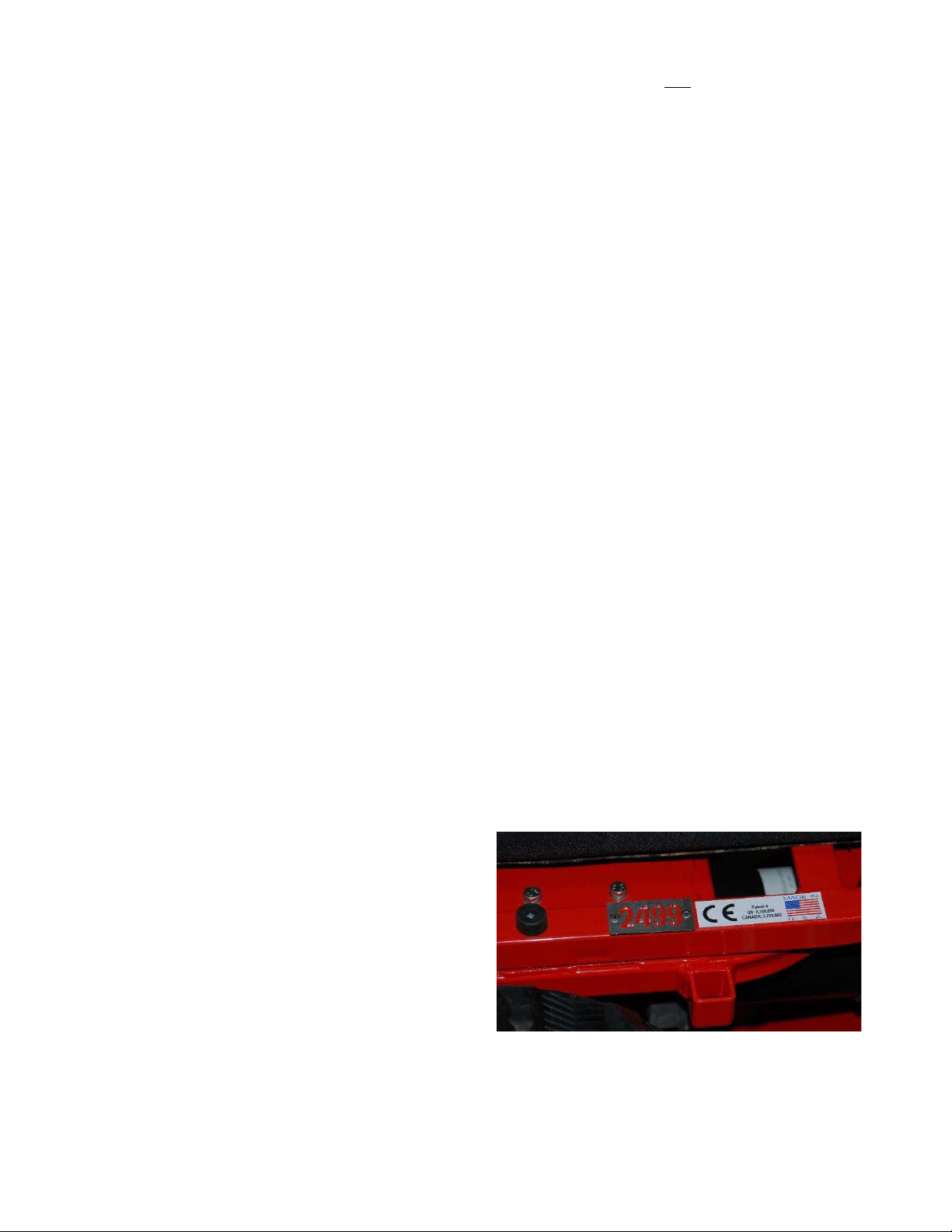
Label Locations
Serial number plate and patent numbers
for the Falcon and the Eagle models are
located on the left side of the seat base
frame as viewed from the seated
position. On the Hawk model you will
find the serial number plate below the
front edge of the seat cushion.
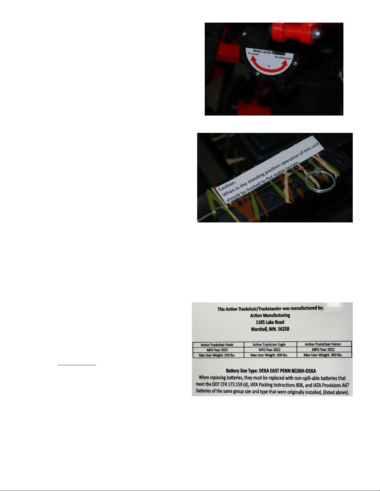
Page | 6
Manual Brake release lever labels are
located on the back of each motor.
Trackstander Falcon and Hawk models with the
Stand up option will have the caution label
Located on the left side of the seat base near
the left footrest down tube.
Battery Specification and wheelchair information is contained on a label that is located in close
proximity to the battery, (sample format below).
This Action Trackchair/Trackstander was
manufactured by:
Action Manufacturing
1105 Lake Road
Marshall, MN 56258
Model:
MFG. Year: 20XX
Max user weight: 300 lbs. (250 lbs. for the Hawk)
Battery size Type: DEKA EAST PENN 8G30H-DEKA
When replacing batteries they must be replaced with non-spill-able batteries that meet DOT CFR
173.159 (d), IATA Packing Instructions 806, and IATA Provisions A67 batteries of the same group size
and type that were originally installed, (listed above).

Page | 7
Device Description Trackstander
Action Trackstander Falcon principles of operation
•
One of the design characteristics of the Action Trackstander Falcon models 1816, 1820, 2016,
2020 is that the occupant seat mechanism is engineered so that through the use of dual hinge
systems, one located on the leading edge of the seat base and a second hinge system located
between the trailing edge of the seat base and the bottom edge of the seat back. These two
hinge systems working together with an electric actuator that is controlled by the occupant,
allow the Trackstander seat to automatically convert from a sit down (seated) configuration to
the up- right (standing) configuration.
•
Another design characteristic of the Action Trackstander Falcon models 1816, 1820, 2016,
and 2020 is the feature that allows the occupant to adjust the tilt angle of the seat
base/backrest to achieve a variety of positioning angles.
•
A third design characteristic of the Action Trackstander Falcon is through the use of rubber
tracks, it is the rubber tracks that allow the occupant to operate in non-traditional environments
commonly found in areas where there is an absence of sidewalks and or hard surface
streets/roads and where the terrain would prohibit the use of traditional wheeled type
wheelchairs.
Proposed Conditions of Use for the Action Trackstander
The design characteristics of the Action Trackstander are intended to be used to provide mobility to
individuals whose living environment does not have accommodations of flat level hard surfaces to
facilitate the use of traditional wheelchairs and who otherwise would be confined to the inside of
their home.
Because the Action Trackstander utilizes two rubber tracks as part of the drive system it can traverse
uneven terrain comprised of soft sand, mud, snow, or other similar surfaces. Additionally, the Action
Trackstander has the ability to raise occupants up to the standing position.
Device Description Trackchair
Action Trackchair Eagle and Hawk models principles of operation
•
A design characteristic of the Action Trackchair Eagle models Eagle 16, Eagle 18, Eagle 20,
Eagle 22, Eagle 24 and Hawk 14, 16, 18, 20 and 22 is the feature that allows the occupant to
adjust the tilt angle of the seat base/backrest to achieve a variety of positioning angles to
facilitate occupant comfort.
•
Another design characteristic of the Action Trackchair Eagle and Hawk models is through the
use of rubber tracks, it is the rubber tracks that provide adequate traction and stability to allow
the occupant to operate in non-traditional environments commonly found in areas where there
is an absence of sidewalks and or hard surface streets/roads and where the terrain would
prohibit the use of traditional wheeled type wheelchairs.

Page | 8
Proposed Conditions of Use for the Action Trackchair Eagle and Hawk
The design characteristics of the Action Trackchair Eagle and Hawk models are intended to be used
to provide mobility to individuals whose living environment does not have accommodations of flat
level hard surfaces to facilitate the use of traditional wheeled type wheelchairs and who otherwise
would be confined to the interior of their home.
Because the Action Trackchair Eagle and Hawk utilizes two rubber tracks as part of the drive system
it can traverse uneven terrain comprised of soft sand, mud, snow, or other similar surfaces while
providing stability and traction. These types of terrain are typical conditions that are found in area
where there is a lack of hard surfaces like sidewalks, streets/roads.
Operating Your Action Trackchair/Trackstander
Directions for Use
Because the Action Trackchair/Trackstander utilizes two rubber tracks as part of the drive system it
can traverse uneven terrain comprised of soft sand, mud, snow, or other similar surfaces.
Additionally, the Action Trackchair/Trackstander has the ability to raise occupants up to the
standing position. Because of these unique capabilities it is important to read and understand the
following directions for use.
•
Make sure the joystick control is in the off position before transferring into and
out of the Trackchair/Trackstander.
•
The joystick control has five speeds, (1 through 5) that can be selected using the blue up and down
arrows on the face of the joystick.
•
A battery charge indicator is located on the main screen of the joystick. Observe the level of charge
before and while operating the Trackchair/Trackstander so you remain aware of the battery charge
status as you operate the Trackchair/Trackstander. Battery life between charges is affected by several
variables such as; the level of charge when you start driving, age of batteries, weight of operator, and
the type of surface operated on (soft or hard, hilly or flat). The Action Trackchair/Trackstander has a
built-in battery charger that can be plugged into any standard household outlet (115 voltages).
Caution: always remember to unplug the battery charger before operating the
Trackchair/Trackstander. Do not drive/operate the Trackchair/Trackstander while the batteries are
being charged.
•
Optional lighting is available and is controlled on the joystick control panel by depressing the light
symbol once to turn on and again to turn off.
•
Tilting of the seat on the Trackchair/Trackstander is possible by pushing the “tilt on the fly” rocker
style switch located at the end of the armrest.

Page | 9
•
The tilting of the seat can be achieved while driving in forward or reverse.
•
To activate the stand-up function on the Trackstander push the “M” button on the joystick control,
and then move joy stick lever forward to stand, backward to sit. Cancel by pushing “M” again or
moving joystick lever to the left.
•
Insure that the footrest plate is adjusted to a comfortable setting.
•
Always wear the seat lap belt and/or the 4 point shoulder harness as provided on all models as
well as the leg stabilizer straps (Falcon and Hawk models).
•
The operation of the joystick lever is similar to other readily available power wheelchairs. For forward
movement push the joystick lever in the direction that you want the chair to move towards. Release
the joystick lever to stop.
•
If your Trackchair/Trackstander has the joystick locking feature enabled, it can be unlocked in this
way. Turn control on, hold joystick lever forward until you hear a beep (or for a three second period),
then move the joystick lever backwards until you hear a beep (three second period). It is now
unlocked and ready for operation. To lock the joystick, press and hold the on/off button until the
control has cycled both on then off. At this point the joystick is locked.
Comfort Adjustments
The following adjustments can be made to customize the Trackchair/Trackstander to suit the needs of the
individual operator.
•
The footrest can be moved up or down to fit the operator’s specific needs, this can be
accomplished by relocating the foot rest locating pins. No tools are required to make this easy
adjustment.
•
The Trackchair/Trackstander seat tilt angle can be adjusted to suit the desired comfort needs of the
operator. This is accomplished by simply pushing the tilt on the fly rocker switch or by using the
joystick. No tools are required to make this adjustment.
•
The armrests can flip back (up) for easier transferring into and out of theTrackchair/Trackstander.
Page | 10
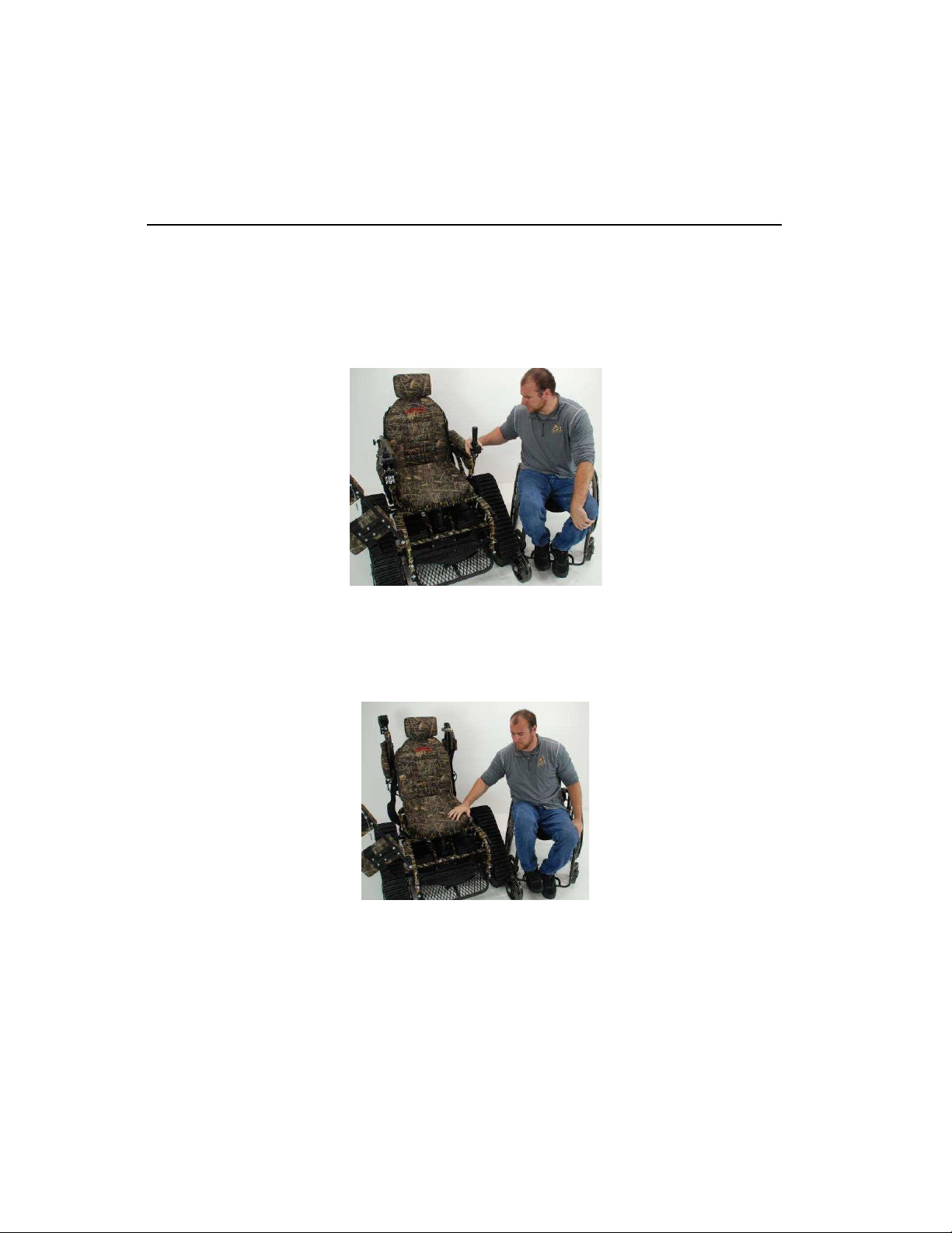
Transferring into your Action Trackchair/Trackstander
•
Know your abilities, if you need an assistant to safely transfer, have someone assist.
•
Always transfer into and out of your Trackchair/Trackstander when on firm levelterrain.
•
Before you begin your transfer ensure that the joystick control has been turnedoff.
•
Transfers can be made from the front or from either side, select the method that best fits your
abilities.
•
When you are ready to transfer, bring your regular chair into position next to the
Trackchair/Trackstander and lock the brakes on the chair that you are transferringfrom.
•
The armrest assembly can be rotated upwards/backwards to facilitate transfer
Page | 11
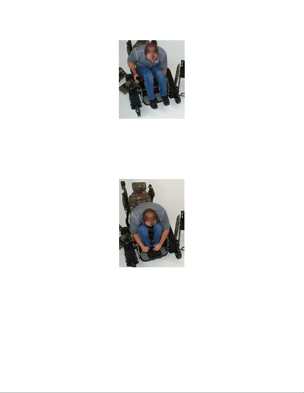
•
Once you have made the transfer, place your feet onto the foot rest platform.
•
The Trackchair/Trackstander is equipped with a foot strap that can be used to keep your feet
firmly located on the foot rest. Open the Velcro strap closure and remove the strap from the D
ring, place this strap in front of your ankles, insert the strap through the D ring and secure the
Velcro strap to the mating Velcro material. When properly completed there will be a strap in
front of and behind your ankles to control forward and rearward movement of your feet.

Page | 12
•
Move the knee pad bolster frame down (Trackstander model) and secured it with the pin as
shown.
•
Place the leg support straps (Trackstander model) behind the upper portion of your calf (just
below the knee) and secure the strap through the D ring. Repeat for the other leg.
•
Place the 4 point harness over your shoulders with each arm exiting through the side of the
harness as shown in the photo. Tighten the side and upper harness straps sufficiently to secure
your upper body based on your individual preference.

Page | 13
•
Before you turn on the joystick recheck the following;
o
Is the four point harness properly secured as shown?
o
Is the knee bolster frame down and secured with the pin as shown?
o
Are the knee support straps properly routed behind the lower leg, through the D ring and
is the strap pulled tight and placed onto the mating Velcro material?
o
Are your feet located on the footrest so that your heels are against the back edge of
the footrest?
Battery Information
•
The batteries supplied with your new Trackchair and or Trackstander are manufactured by East Penn
Manufacturing Co. Deka Road, Lyon Station, PA. 19536-0147, these batteries meet the requirements
as defined in ISO-7176-25 and IEC 60254-1.
•
Specifically:
o
The batteries comply with the 300 cycle-- cyclic endurance test standards of IEC 60254-1
o
The batteries are warrantied for a period of 12 months.
o
Replacement batteries can be obtained from an authorized Batteries Plus distributor
(www.batteriesplus.com/store-locator) or from the Action Trackchair dealer that you
purchased your Trackchair or Trackstander from. A list of dealers can be found at
www.actiontrackchair.com click on “find dealer” or by calling Action Manufacturing at 507-
532-5940.
o
All batteries are affected by ambient temperature, the East Penn batteries have the following
temperature induced performance percentages.
▪
At 77 degrees F the batteries will deliver 100% of their ratedcapacity.
▪
At 32 degrees F the batteries will deliver 86% of their ratedcapacity.
▪
At 104 degrees F the batteries will deliver 103% of their ratedcapacity.
o
If the Trackchair/Trackstander will not be used for extended periods of time and it will be
exposed to ambient temperature below 32 degrees F the batteries must be fully charged
before entering storage. It is recommended that the battery charger remain connected to AC
power while the unit is in storage. If this is not possible then the batteries should be recharged
every 60 days at a minimum.
o
All batteries can produce explosive gases during recharge, when recharging the batteries it is
recommended that the Trackchair/Trackstander be located in a well ventilated area awayfrom
sparks or other sources of ignition.
o
Battery maintenance is minimal, our GEL batteries are sealed and thus will not require the
checking of or addition of battery fluid. Keep the batteries clean, make sure the battery
cable attachment bolts are tight and charge the batteries after each use. Keep the charger
connected to the batteries during periods of prolonged storage.

Page | 14
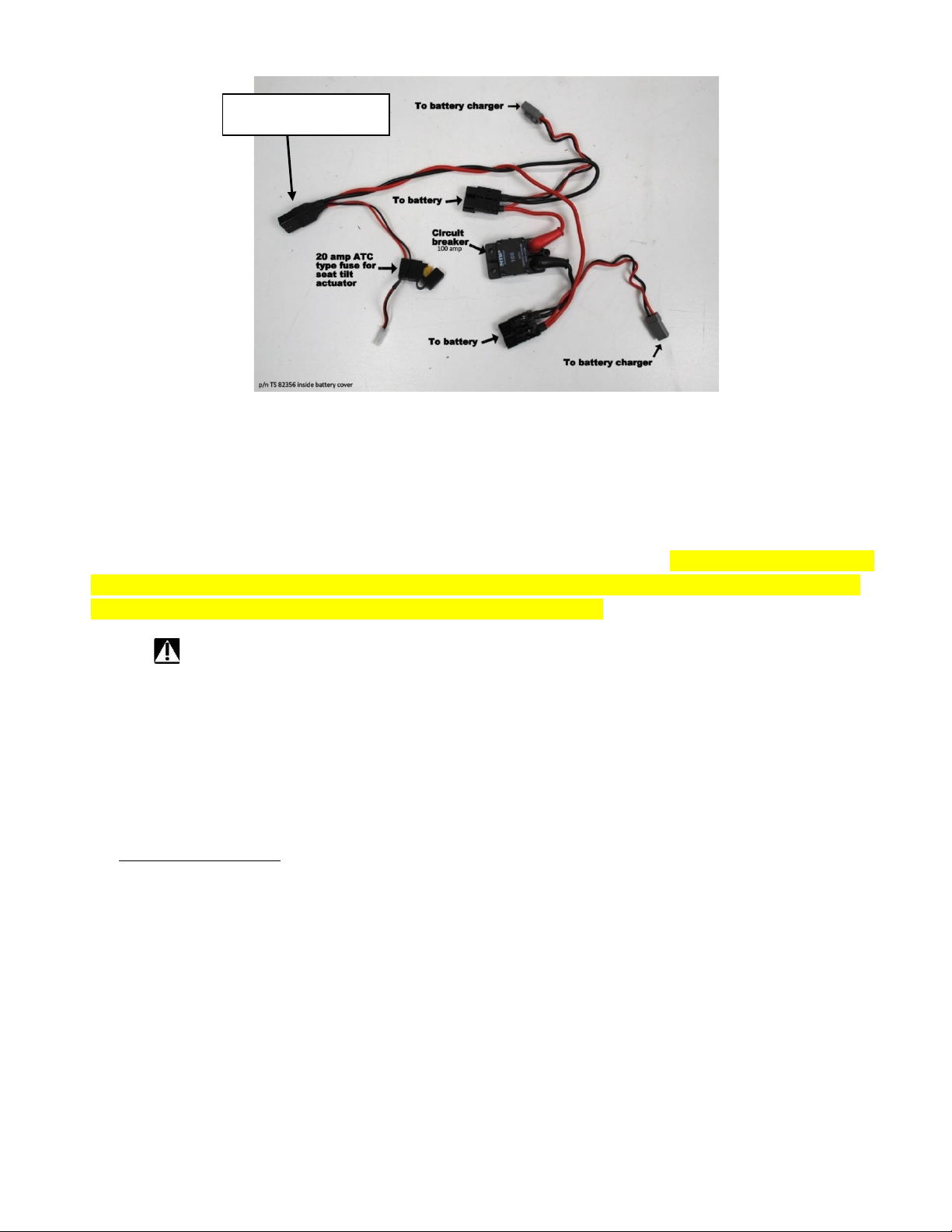
Connections to the batteries must be completed as shown below
1.
The battery wire harness ground wire (black in color) with the –symbol must be connected to the
battery terminal that is identified with the –symbol and having a black colored ring around the
battery bolt.
2.
The battery wire harness positive wire (red in color) with the + symbol must be connected to the
battery terminal that is identified with the + symbol and having a red colored ring around the
battery bolt. Improper connections could cause damage to the unit or may result in injury.
The wire connections from each battery to the main wire harness are identical, the wire harness for
each battery is also identical (see figure #1).
Main circuit protection is provided with a 100 amp circuit breaker. The tilt system fuse is an ATC style
20 amp rated fuse (see figure #2).
Figure #1
Page | 15
Figure #2
Batteries and Charging
Listed directly below are the key operating principles of the Pro Mariner Dual Pro battery charger. The complete
Dual Pro battery charger operating instruction manual is listed starting on page 32. The Dual Pro battery charger
contains an integrated drive inhibit feature, this feature prevents the Trackchair from being driven away when
the battery charger is plugged into the wall outlet to charge the batteries.
Warning batteries contain stored electrical energy, always use caution when working near the batteries.
Always read the battery charger owner’s manual that is included with the Trackchair/Trackstander wheelchair. The
complete battery charger operating instruction manual is also provided in this Owner’s Manual and can be found
starting on page 32.
•
Battery charge will last up to ten miles, depending on battery condition (age) and type of use the
Trackchair/Trackstander is subject to (terrain and weight of operator).
•
The Trackchair/Trackstander has a built-in battery charger that plugs into 115 volt household current.
•
Pro Mariner Charger:
ProSport includes 7 LEDs for operation status and up to 3 battery bank trouble LEDs depending
on the model.
1. The blue AC power LED
Illuminates when AC power is applied
2. The battery type LED
Will illuminate red for standard Flooded (lead-acid)/AGM and green for GEL.
Note: The ProSport 20 Dual bank model includes an amber battery type LED for AGM HP
(High Performance) battery type. Please read the battery manufacturer literature carefully
and select the correct charge profile. Failure to do so may cause early battery failure.
3. The system check OK LED
After applying AC power the ProSport will self-test and analyze all battery connections
and batteries. If all checks are OK the green LED will illuminate. This can take up to 2 minutes.
4. The charge mode LEDs
Charging: Red LED will flash during the self-test and battery test mode
(approximately 1-2 minutes) and will be solid red during charging.
To Motor Controller

Page | 16
Conditioning: Amber LED illuminates during conditioning mode.
Ready / maintain: Green LED illuminates when batteries are fully charged and being
automatically maintained until you are ready to use your boat.
Storage recondition: Green LED fades in and out when performing a once a month storage
recondition mode.
5. Battery bank trouble status LEDs
Red LEDs will illuminate indicating a wiring problem or fault at one of the batteries connected
to the ProSport charger. See page 21 of charger manual for further details.
Operation after Applying AC Power to a ProSport Charger
Connected to Discharged Batteries
During the startup test the battery type LED will be illuminated and the red charge mode LED will
flash indicating that the unit is in a self-test mode. When complete and if there are no faults, the
charger's system check OK indicator will illuminate green and the ProSport's solid red charging
LED will be ON indicating the charge process is initiated.
Note: If there is a fault the appropriate bank LED will illuminate and the charge process may not start, depending
on the location of the fault. See page 21 for further troubleshooting details.
If There are no Battery Faults, the Green System Check OK LED will Illuminate and the
Following Sequences will proceed:
The red battery type LED (factory set for standard Flooded (lead-acid)/AGM batteries) will illuminate.
The red charge mode LED will illuminate indicating the charger has started its multi-stage charging process.
When the charge process is approximately 80% complete the red charge mode indicator will
turn off and the amber conditioning LED will turn on indicating the conditioning mode.
When the multi-stage charge process is completed you will observe the following:
Battery type red LED goes OFF.
The red charging LED and the amber conditioning LED will be off and the green ready/maintain
LED will illuminate indicating your batteries are fully charged.
The only LEDs on after the multi-stage charge process is completed are the green system
OK LED, blue AC power LED and the green ready/maintain LED.
Multi-Stage Charging Overview
ProSport Charging: During this mode the “Charging” indicator will be red. ProSport will use all of its
available charging amps (as controlled by temperature) until the battery voltage is raised to 14.6VDC
(Flooded lead-acid factory setting).
ProSport Conditioning: During this mode the “Conditioning” status indicator will be amber. Batteries will
hold at 14.6 VDC (factory set for Flooded lead-acid batteries) to complete charging while conditioning each
battery connected. Upon completion the ProSport will go into it’s maintain mode.
ProSport Ready / Maintain: During this mode the “Ready/Maintain” status indicator will be green and remain
on with the blue “power” LED indicating that your batteries are fully charged while being maintained at a precision
13.4 volts (factory set for flooded lead-acid batteries) and are ready to go when you are.
ProSport Storage Recondition Mode: During this mode the ProSport “Recondition Mode” green indicator
will illuminate with a slow fade in and out pulse indicating that while your batteries/boat are in storage the
ProSport will automatically recondition all batteries for up to 3 hours once a month extending battery life
and maximizing on the water battery power performance.
Batteries and Charging (Continued)
•
To get maximum daily use, the battery must be fully charged. This is accomplished by having the
Trackchair/Trackstander plugged in until the “READY LIGHT” comes on.
•
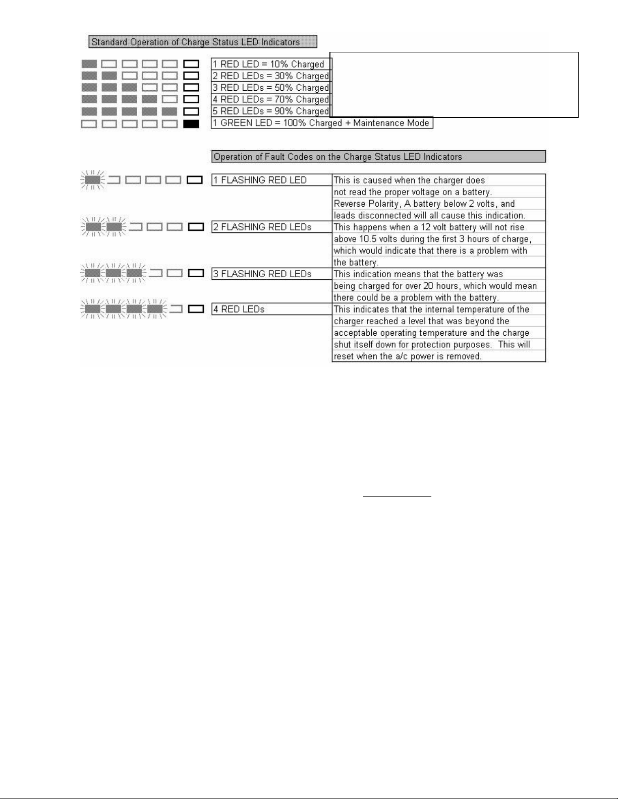
Dual Pro Charger:
When your battery charging system is activated, each bank provides charging information utilizing five red Light
Emitting Diode (LED) indicators and one green Light Emitting Diode (LED) indicator.
The five red LEDs enable you to track the progress of the charge cycle on each battery as the voltage
rises.
Page | 17
Battery life, long term storage and care.
•
Our batteries are GEL technology which means they are lighter weight, spill proof and do not carry the
hazardous material classification like typical lead acid batteries. GEL batteries are maintenance free,
deliver high currents on demand and offer a relatively long service life. While typical lead acid
batteries need a topping charge every six months to prevent the buildup of sulfation, GEL batteries
are less prone to sulfating and can sit in storage longer before a charge becomes necessary. The GEL
battery stands up well to low temperatures and has a low self-discharge rate.
•
Whenever you are not using your Trackchair/Trackstander it is always recommended to leavethe
battery charger connected to the Trackchair/Trackstander. The battery charger willcontinually
monitor the battery’s state of charge and will provide charging when/if needed. Follow this same
procedure for long term storage.
•
When replacing batteries, they must be replaced with non-spillable batteries that meet DOT CFR
173.159 (d), IATA Packing Instructions 806, and IATA Provisions A67 batteries of the same group/size
and type that were originally installed.
2 to 12.78 volts = 10%
12.79 to 13.25 volts = 10%, 30%
13.26 to 13.49 volts = 10%, 30%, 50%
13.50 to 14.04 volts = 10%, 30%, 50%, 70%
14.05 to 14.52 volts = 10%, 30%, 50%, 70%, 90% Green Flashing
{Finishing Stage} 14.52 to 15.49 volts

Page | 18
Battery Replacement Procedure
Warning—Use care when working around batteries, metallic objects such as a wrench can cause a
short circuit between the battery posts (the –and + terminals). A short-circuit will result in sparks and
could cause an explosion. Always use safety gloves and protective eyeglasses when working with
batteries.
•
Always have your batteries replaced by a properly trained mobility technician or a person with
adequate knowledge about batteries, electrical and mechanical systems. They have the
technical expertise and the tools to complete the job in a safe manner.
1.
Make sure that the joystick is turned off before starting this procedure.
2.
Lift the knee pad support bar up and to the side, (see figure #3 below).
3.
Tilt the seat and backrest to the full rearward position and remove the lower footrest by removing
the four spring clips that secure the footrest to the vertical down tubes (see figure#3 below).
4.
Remove the six bolts that secure the horizontal support bar to the main frame of the
Trackchair/Trackstander (9/16” wrench and socket with ratchet) (see figure #3below).
5.
Remove the four nuts that secure the battery hold down brackets using a 7/16” wrench or socket
with ratchet (see figure #4 below).
6.
Remove the two metal hold down brackets located on the top of the batteries, remove the battery
covers (see figure #4 below).
7.
Starting with one of the batteries, remove the two bolts and washers that secure the red and
black wires to the battery. Slide the old battery out from the battery compartment and slide the
new battery into the battery compartment making sure to orientate the new battery so that the
battery terminals are positioned towards the center of the Trackchair/Trackstander.
8.
Reattach the red and black wires to the battery terminals using the bolts and washers removed in
step #7, make sure that the red wire is connected to the battery terminal marked with the + POS
symbol. The black wire should be connected to the battery terminal marked with the –NEG
symbol. (See figure #5 below)
9.
Repeat step #7 for the remaining battery.
10.
Replace the battery covers, the battery hold down brackets and re-secure with the washersand
nuts that were removed in step #5.
11.
Re-install the horizontal steel bar with the six bolts, washers and nuts. Re-install the footrest with
the four spring clips.
12.
Battery replacement is complete.

Page | 19
This manual suits for next models
2
Table of contents
Other Action Trackchair Truck manuals


