Action Trackchair STS User manual

www.actiontrackchair.com 0

www.actiontrackchair.com 1
Table of Contents
Safety Instructions...................................................................................................... 2
Trackchair®Helpful Hints ........................................................................................... 3
Trackchair®Comfort Adjustments ............................................................................ 4
Batteries and Charging............................................................................................... 5
Repairs and Maintenance........................................................................................... 7
Cleaning your Action Trackchair®.......................................................................... 10
Warranty ................................................................................................................... 11
Joystick Diagnostic Reference ................................................................................ 12
Transporting your Action Trackchair®.................................................................... 14
Rocker Switch Override Instructions ...................................................................... 15
Law, Regulation and Policy for Wheelchair/Mobility Device use in “Federally
Designated Wilderness”........................................................................................... 16
Notes.......................................................................................................................... 17
1105 Lake Road
Marshall, MN 56258
(507) 532-5940

www.actiontrackchair.com 2
Safety Instructions
Please review and adhere to the following safe use guidelines.
•Do NOT ride on the Action Trackchair®during loading or unloading from vehicle or trailer.
•Only one person should be on the Action Trackchair®at any time.
•A seatbelt is required when operating the Action Trackchair®.
•Keep hands and fingers away from the rotating parts of the tracks and pinch points.
•Make sure controls are turned OFF when getting in or out of the seat.
•Make sure controls are turned OFF before placing a cover over the Action Trackchair®.
•When approaching inclines or declines in any surface always use caution, switch to a slower
speed.
•The Action Trackchair® will climb inclines enough to tip over in any direction.
•Do NOT attempt to climb stairs in the Action Trackchair®.
•When climbing over obstacles, approach at an angle, NOT perpendicular.
•Do not drive the Action Trackstander® in the upright position on uneven or rough terrain.
•Do NOT navigate Action Trackchair®on more than a 20-degree slope
Failure to know the limits and to adhere to the above items could cause personal injury or
equipment damage.

www.actiontrackchair.com 3
Trackchair®Helpful Hints
•When you are transferring into your Trackchair®, make sure the controls are in the OFF position
before sitting in the Trackchair®.
•When operating your Trackchair®, make sure you are securely fastened in with either the lap belt
or 4-point harness.
•Your Trackchair®can be programmed by your dealer to have the option of locking the joystick.
•When locking the control, follow the process below:
•Turn control OFF, hold ON/OFF button until the control has cycled both ON and then
OFF. Control is now set in the locked mode.
•If your Trackchair®has a locking control, it can be unlocked in the following way:
•Turn the control on, hold joystick forward until you hear a beep or three seconds and
then pull the joystick back until you hear a beep or three seconds. It is now unlocked
and ready for operation.
•The Trackchair®control has five speeds, one – five can be changed with the up and down arrows.
•The battery indicator is on the main screen of the controls. Battery charge will last up to
approximately four hours, depending on battery condition and type of use the Trackchair®is
subject to. Action Trackchair®has a built-in battery charger that plugs into a 120-volt outlet for
North America, or a universal charger if sold overseas for AC voltage from 90 volts to 240 volts.
•Optional lighting is available and is controlled on the joystick control panel.
•If it is necessary to pull the Trackchair®, disengage the brakes on the motors with the levers on the
back of the motors. Push levers to the outside on both motors. Do not pull the Trackchair®over 5
MPH.
•Action Manufacturing does not recommend operating your Trackchair®in salt water. Although the
Trackchair® is powder coated to the highest quality with very durable powder coat, salt water is
very corrosive and can cause problems with powder coat and metal. If your Trackchair®has been
exposed to salt water, rinse the Trackchair®completely with fresh water and dry off.

www.actiontrackchair.com 4
Trackchair®Comfort Adjustments
There are a few adjustments that are needed when first setting up your chair. The footrest can be
moved up or down to fit the rider’s needs. The chair itself can be leveled to the desired comfort of the
rider. The armrest can flip back for easier transferring into the chair. Electronic controls can be
adjusted by a servicing dealer regarding speed, acceleration, deceleration, braking, etc.
•ST/TR/STS/NT will tilt forward and backward by depressing the rocker switch on the grab handle.
•ST/STS arms will move up and down by pulling the pin on the rear of arm and lifting. TR arms will
move up and down simultaneously. NT/NR arms move up and down independently.
•NR knee pads and arm rests can be adjusted up and down, in or out, and forward or backward.
•TR knee pads can be adjusted up and down, forward, or backward.
www.actiontrackchair.com 5
Batteries and Charging (Dual Pro 120V AC only)
The Action Trackchair®will not drive while the chair is plugged
into the wall outlet and charging the batteries.
•Battery charge will last up to four hours, depending on battery condition, temperatures, and type of
use the Trackchair®is subject to (terrain and weight of rider). The Trackchair®has a built-in
battery charger that plugs into the outlet. (Power factor corrected charger for overseas)
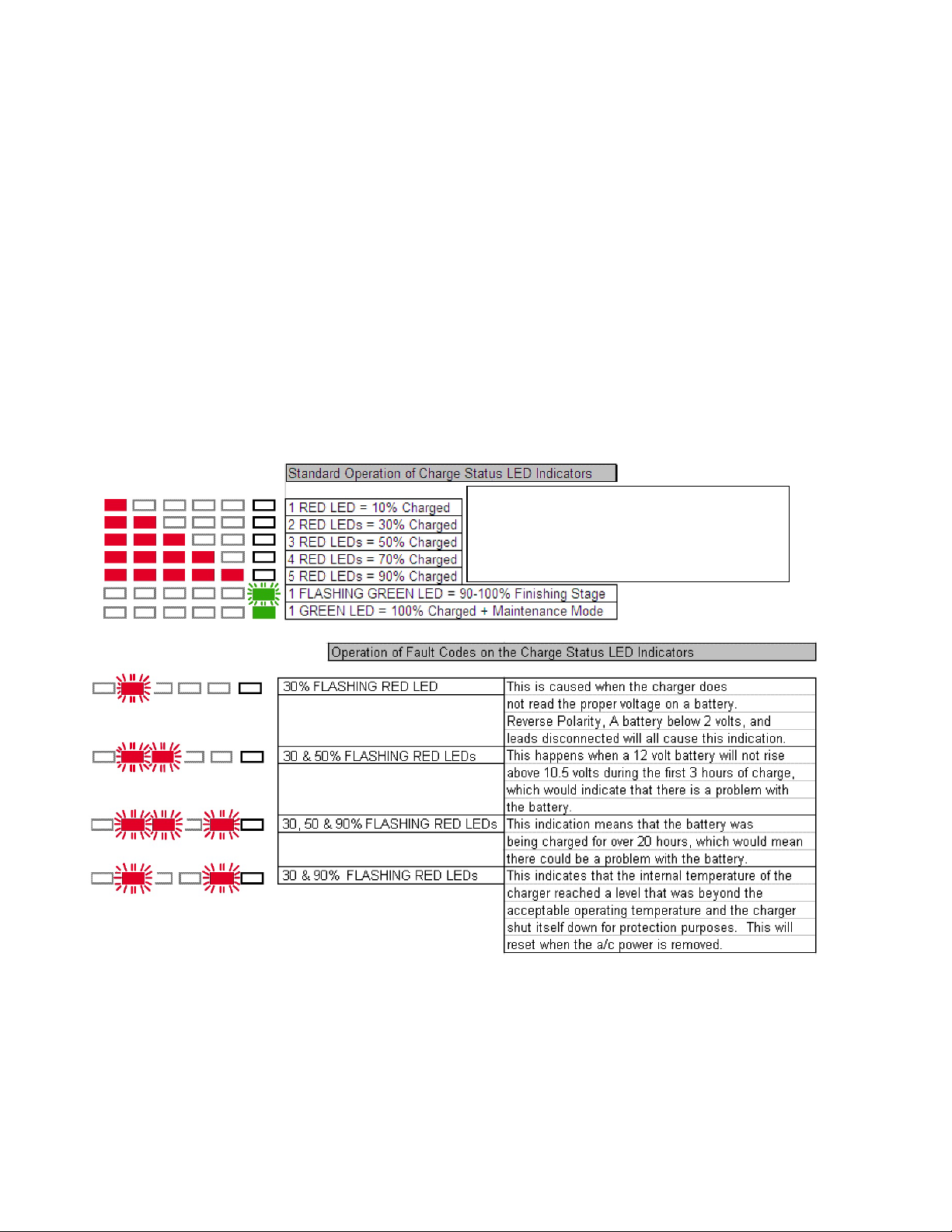
INDEPENDENT CHARGING BANK INDICATIONS (Dual Pro 20 AMP 120V only)
•When your battery charging system is activated, each bank provides charging information utilizing
five red Light Emitting Diode (LED) indicators and one green Light Emitting Diode (LED) indicator.
•The five red LEDs enable you to track the progress of the charge cycle on each battery as the
voltage rises. See chart below:
•The batteries are fully charged when the Dual Pro charger has both green LED’s on solid.
•The charger can be left on for an extended period without harming the battery.
Your system provides an equalization stage every 30 days while plugged in. If the charger is normally disconnected from A/C after completing charge,
equalization can be accomplished by plugging back into A/C whenever this stage is desired. Battery manufacturers recommend that equalization is done
once a month in order to further reduce sulfation on the lead plates of a battery, which helps promote longer battery life. Note: During this process the
LEDs will go through their normal routine (Red counting up for % of charge) and the Green Led will blink until the unit returns to the maintenance mode
and a steady Green LED. (Not applicable to a Gel Profile)
2 to 12.78 volts = 10%
12.79 to 13.25 volts = 10%, 30%
13.26 to 13.49 volts = 10%, 30%, 50%
13.50 to 14.04 volts = 10%, 30%, 50%, 70%
14.05 to 14.52 volts = 10%, 30%, 50%, 70%, 90% Green Flashing
{Finishing Stage} 14.52 to 15.49 volts
www.actiontrackchair.com 6
Batteries and Charging – EU Models (ProSport)
•Operation after applying AC Power to the ProSport Charger connected to discharged batteries.
(European Models Only)
During the startup test the battery type LED will be illuminated and the red charge mode LED will flash indicating
that the unit is in a self-test mode. When complete and if there are no faults, the charger's system check OK
indicator will illuminate green and the ProSport's solid red charging LED will be ON indicating the charge process
is initiated. Note: If there is a fault the appropriate bank LED will illuminate and the charge process may not start,
depending on the location of the fault.
•If there are no Battery Faults, the Green System Check OK LED will illuminate and the following
sequences will proceed:
•The red battery type LED (factory set for standard Flooded (lead-acid)/AGM batteries) will illuminate.
•The red charge mode LED will illuminate indicating the charger has started its multi -stage charging process.
•When the charge process is approximately 80% complete the red charge mode indicator will turn off and the
amber conditioning LED will turn on indicating the conditioning mode.
•When the multi-stage charge process is completed you will observe the following: Battery type red LED goes
OFF.
•The red charging LED and the amber conditioning LED will be off, and the green ready/maintain LED will
illuminate indicating your batteries are fully charged.
•The only LEDs on after the multi-stage charge process is completed are the green system OK LED, blue AC
power LED and the green ready/maintain LED.
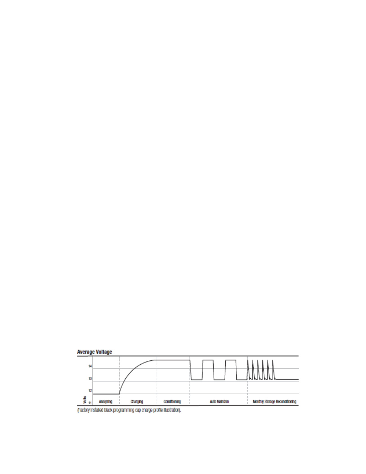
•Multi-Stage Charging Overview
Stage 1 - System Check OK and Battery Analyzing: During this stage the ProSport red “Charge” LED will flash
indicating ProSport is analyzing all battery connections in addition to checking each battery is capable of being
charged. Upon completion the “System Check OK” indicator will illuminate green followed by Stage 2 Charging.
Stage 2 - Charging: During this mode, the “Charging” indicator will be red. The ProSport Series will use all its
available charging amps
(as controlled by temperature) until the battery voltage is raised to 14.6VDC (Flooded lead-acid factory setting).
Stage 3 - Conditioning: During this mode, the “Conditioning” status indicator will be amber. Batteries will hold at
14.6 VDC (factory set for Flooded lead-acid batteries) to complete charging while conditioning each battery
connected. Upon completion the ProSport will go into its Energy Saver Mode.
Stage 4 - Auto Maintain (Energy Saver Mode): During this mode, the blue “Power” and green “Auto Maintain”
LED's will be on indicating Stage 2 charging and Stage 3 conditioning are completed. At this time ProSport will
initiate its Auto Maintain (Energy Saver Mode) which will monitor and Auto Maintain batteries only when needed
to maintain a full state of charge.
Stage 5 - Storage Recondition Mode: During this mode, the ProSport “Storage Recondition Mode” green
indicator will illuminate with a slow fade in and out pulse. This indicates that while your batteries/boat are in
storage the ProSport will automatically recondition all batteries for up to 3 hours once a month extending battery
life and maximizing on the water battery power performance.
To get maximum daily use, the battery must be fully charged. This is accomplished by having the
Trackchair®plugged in until the “READY LIGHT” comes on, on the battery charger.

www.actiontrackchair.com 7
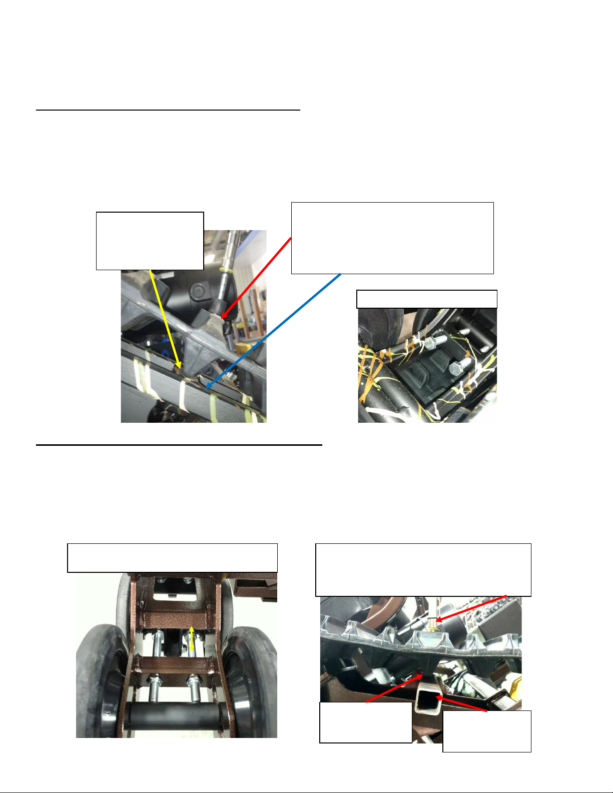
Elevate chair with suitable lift or blocks, here you
see the K&L model MC455 fat jack.
Track adjuster bolts
Press down on track with 20-25 lbs. of force and observe
location of track lug. When properly tensioned the lug at the
blue arrow should be about 1” from the frame with 20-25
lbs. of force. Rotate track to check measurement at 3
different locations around the track to confirm measurement.
Use suitable spring tension gauge
purchased from your dealer (PN 80500)
Locate track lug perpendicular to idler wheel
mounting bolt towards front of chair as shown.
Front of chair
Repairs and Maintenance
Track adjustment procedure for NT/NR models
Tracks can be adjusted by loosening both bolts on the front idler wheels, inside and outside. Track
tensioners can be tightened with a 9/16 wrench by turning track tensioner bolts clockwise an even
amount. Adjustment is only needed if the track tension does not meet the below specification. IT IS
NOT NECESSARY TO OVER TIGHTEN THE TRACKS. Re-tighten front idler wheels, inside and
outside to 130 in./lbs.
www.actiontrackchair.com 8
Use suitable spring tension gauge to properly
press against a 1” tube or comparable 1”
measurement. Force should be 25-30 lbs. of force
as track lug touches 1” tube.
Line up track lug
on center of “A”
frame as shown.
1” tube for
distance
reference only.
Repairs and Maintenance (cont.)
All bearings are sealed and need no additional greasing.
Track adjustment procedure for ST/TR models
Tracks can be adjusted by loosening both bolts on the front idler wheels, inside and outside. Track
tensioners can be tightened with a 9/16 wrench by turning track tensioner bolts clockwise an even
amount. Adjustment is only needed if the track tension does not meet the below specification. IT IS
NOT NECESSARY TO OVER TIGHTEN THE TRACKS. Re-tighten front idler wheels, inside and
outside to 130 in./lbs.
Track adjustment procedure for STSx/STS models
Tracks can be adjusted by loosening the bolt on the rear idler wheels. Track tensioners can be
tightened with a 9/16 wrench, or swivel socket with extension by turning track tensioner bolts
clockwise an even amount. Adjustment is only needed if the track tension does not meet the below
spec. IT IS NOT NECESSARY TO OVER TIGHTEN THE TRACKS. Re-tighten front idler wheels,
inside and outside to 130 in./lbs. Trackchair must be elevated when checking the tension of tracks,
when lowered to the ground, they will relax a little.
Rotate the track so an
internal lug is directly
above the “A” frame
cross support as shown.
Press down on track with 20-25 lbs. of force
and observe location of track lug. When
properly tensioned the lug should just contact
“A” frame at bottom right of picture with 20-25
lbs. of force. Note blue arrow.
ST/TR track adjustment bolts
Starting point for bolts from factory is 1 ¾ “ from
head of bolt as seen in picture with yellow arrow.

www.actiontrackchair.com 9
Repairs and Maintenance (cont.)
The Action Trackchair®was constructed with no grease zerks, no tires, no chains, and no pulleys to
minimize maintenance and requires only periodic cleaning to maximize performance. Your daily
maintenance is as simple as plugging in the Action Trackchair® to a standard wall receptacle and
giving it a rinse now and then. This is a very stable, dependable, durable, and user-friendly machine!
Note: Install the black cover provided over the top of the joystick assembly before washing your
Trackchair®. In the event of a lost or severely damaged black cover, use a plastic bag and tape or
rubber glove to protect the joystick.

www.actiontrackchair.com 10
Cleaning your Action Trackchair®
•The Action Trackchair®can be washed with a garden hose. It is not recommended to use a
pressure washer to clean your chair.
•ALWAYS cover the joystick with the black cover provided or with a plastic bag from getting
moisture inside. THE JOYSTICK IS NOT WATERPROOF and should be covered when washing,
stored outside, or when transporting.
•Do not spray water directly onto the motor controller which is under the seat.
•If your Trackchair®has been exposed to salt water, rinse the chair completely with fresh water and
dry off immediately.
•If your Trackchair® has been in the mud, we recommend you rinse the chair completely with fresh
water and dry off immediately.

www.actiontrackchair.com 11
Warranty
Action Manufacturing, 1105 Lake Road, Marshall, MN 56258 gives a ONE YEAR LIMITED WARRANTY on all
components of your Action Trackchair®against defects in material or workmanship.
1-Year: The following components are covered for both parts and labor against manufacture defects in
materials and workmanship for the period of one year.
•Batteries
•Motor Control Box
•Joystick
•Seats
•Tilt Actuator
•Motors
•All Sprockets and Idler Wheels
3-Year: The following components are covered against manufacture defects in materials and workmanship for
the period of three years.
•Dual Pro battery charger
•Tracks (1st Year – Parts and Labor / 2nd and 3rd Years – Parts Only)
•Frame Welding (1st Year – Parts and Labor / 2nd and 3rd Years – Parts Only)
This warranty covers parts and labor charges for repair or replacement of defective parts and begins on the
date of delivery to the original purchaser. This warranty is not transferable to another owner.
This Action Trackchair®limited warranty excludes any failures that are not caused by a defect in material or
workmanship. THIS WARRANTY DOES NOT COVER CLAIMS OF DEFECTIVE DESIGN. This warranty also
does not cover acts of God, accidental damage, normal wear and tear, abuse, or improper handling. This
warranty also does not cover any Action Trackchair®component, or part that has been altered structurally,
modified, neglected, improperly maintained, or purposes other than for which it was designed.
This warranty excludes damages or failures caused by external stress, heat, cold or contamination; abuse,
accident, fire; operator error or abuse; improper component alignment, tension, adjustment or altitude
compensation; snow, water, dirt or other foreign substance ingestion/contamination; improper maintenance;
modified components; use of aftermarket or unapproved components, accessories, or attachments; use of
unapproved software or calibration; unauthorized repairs; or repairs made after the warranty period expires or
by an unauthorized repair center.
This warranty provides no coverage for personal loss or expense, including mileage, transportation costs,
hotels, meals, shipping or handling fees, product pick-up or delivery, replacement rentals, loss of product use,
loss of profits, or loss of vacation or personal time.
If your Action Trackchair®requires warranty service, please contact the Action Trackchair®Dealer in your area.
www.actiontrackchair.com 12
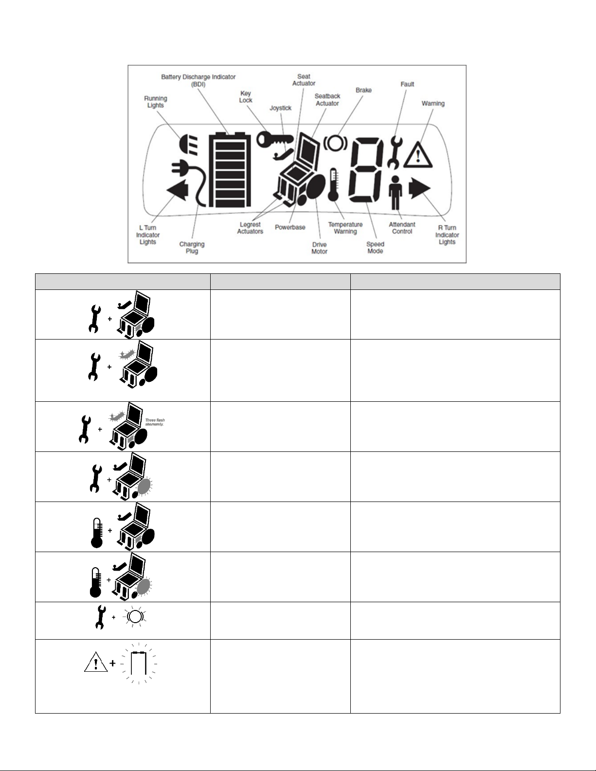
Joystick Diagnostic Reference
Hand Control Display
Fault / Warning
Remedy
Power Section Fault, Main
Relay Fault, or Pre-charge
Fault, or HW Failsafe Fault.
1.Cycle Power.
2.Replace powerbase.
Joystick Fault.
1.Return joystick to neutral and cycle power.
2.Recalibrate joystick.
3.Check joystick cable and cable connections.
4.Replace joystick.
5.Replace hand control.
Communications Fault.
1.Check cable and cable connections.
2.Replace cable.
Open Motor Fault.
1.Check wiring.
2.Replace motor.
3.Replace powerbase.
Controller Over/Under
Temperature Warning.
1.If too hot, wait for controller to cool.
2.If too cold, drive Trackchair®in limited current
mode until controller warms up.
Driver Thermal Warning.
1. Wait for motor to cool.
Brake Fault.
1.Check wiring.
2.Replace motor.
3.Replace powerbase.
Undervoltage Warning.
1.Recharge battery.
2.Replace old battery.
3.Check charger port on hand control; replace
if damaged.
4.If this is happening frequently, replace
charger.
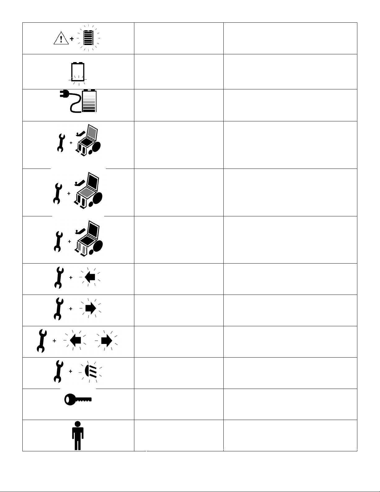
www.actiontrackchair.com 13
Overvoltage Warning.
1.Wait for voltage to come down.
2.Replace old battery.
3.Check charger; replace if faulty.
Low Battery.
1.Recharge Battery.
Battery Charging; Inhibit
1.Unplug charger when charging is complete.
Seatback Actuator Driver
Fault.
1. Select drive or a different actuator;
fault may clear.
2. Check wiring.
3. Check that the seatback is not jammed.
4. Check actuator; replace if faulty.
5. Replace powerbase.
Seat Actuator Driver Fault.
1. Select drive or a different actuator;
fault may clear.
2. Check wiring.
3. Check that the seatback is not jammed.
4. Check actuator; replace if faulty.
5. Replace powerbase.
Leg Actuator Fault.
1. Select drive or a different actuator;
fault may clear.
2. Check wiring.
3. Check that the seatback is not jammed.
4. Check actuator; replace if faulty.
5. Replace powerbase.
Left Indicator Fault.
1. Press Left Indicator button.
2. Replace bulb.
3. If fault continues, check wiring.
Right Indicator Fault.
1. Press Right Indicator button.
2. Replace bulb.
3. If fault continues, check wiring.
Hazard Lights Fault.
1. Press Right or Left Indicator button.
2. Replace bulb.
3. If fault continues, check wiring.
Running Lights Fault.
1. Press Running Lights button.
2. Replace bulb.
3. If fault continues, check wiring.
Locked Mode. *
1. Unlock the system.
Chair Under Attendant
Control*
1.Turn off attendant control (1742).
*These icons indicate a problem only if they appear when they shouldn’t.

www.actiontrackchair.com 14
Transporting your Action Trackchair®
Proper strapping options for the Action Trackchair®to the carrier
***Class III receiver hitch required for carrier. Check automobile manufacturers
recommendation for hitch capacity.
STS/ST/TR Model Photos:
NT/NR Model Photos:
Strap to lower portion of
chair frame in the front.
Strap to lower portion of
chair in the rear.
Strap to lower portion
of chair from the rear.
Strap through footrest,
through carrier and secure
from the front.
Strap around
wheelie bar frame
(Rear, lower view)
Strapping around wheelie
bar – use caution with AC
cord (Rear, top view)
www.actiontrackchair.com 15
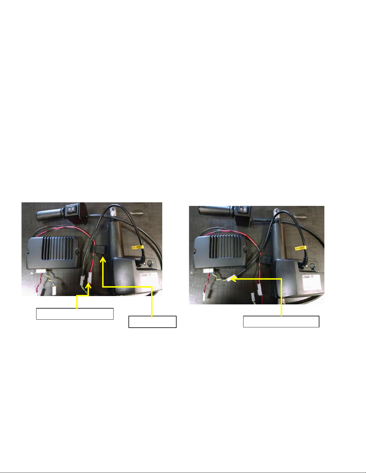
Tilt on the fly wiring harness
Tilt fuse holder
Tilt with joystick connection
Rocker Switch Override Instructions
If the actuator is not moving up or down, follow the steps below:
•First check the fuse in the black fuse holder located at the black and red 16 gauge wire harness
which comes off the battery. Fuse type is an ATC 20 amp.
•If you suspect the actuator has failed and you have a “Tilt on the Fly” rocker switch (not tilt through
the joystick) you can simply bypass the rocker switch as follows:
•Locate wire coming out of the side of the actuator, unplug from the current plug it is
attached to. Plug lead from actuator into blue/yellow lead from the 14-pin connector
which is located under the seat.
•Now turn joystick on and press the “M” button, move the joystick forward or reverse and
the actuator should move up or down.
•If you find the actuator does work, then the problem would be in the “Tilt on the Fly”
rocker switch or wiring to it.

www.actiontrackchair.com 16
Law, Regulation and Policy for Wheelchair/Mobility Device Use in
“Federally Designated Wilderness”
(ADA Title V Section 508c, as amended in 2008)
(1) IN GENERAL – Congress reaffirms that nothing in the Wilderness Act prohibits wheelchair
use in a wilderness area by an individual whose disability requires its use. The Wilderness Act
requires no agency to provide any form of special treatment or accommodation or to construct
any facilities or modify any conditions of lands within a wilderness area to facilitate such use.
(2) Definition – for the purposes of paragraph (1), the term wheelchair means a device designed
solely for use by a mobility impaired person for locomotion, that is suitable for use in an indoor
pedestrian area.” (per American with Disabilities Act, Title V Section 508 (c)
Application: “Designed solely for use by a mobility-impaired person” means that the original design
and manufacture of the device was only for the purpose of mobility by a person who has a
limitation on their ability to walk. “Suitable for indoor pedestrian use” means the device would be
allowed to be used inside a mall, etc.
A wheelchair or mobility device, even one that is a battery powered, that meets both parts of this
definition is allowed anywhere foot travel is allowed including in federally designated wilderness
areas.
The following CFR and FSM apply in ALL areas of the National Forest System
36 Code of Federal Regulation (CFR) 212.1
“Motor Vehicle. Any vehicle which is self-propelled, other than:
(1) a vehicle operated on rails; and
(2) any wheelchair or mobility device, including one that is battery-powered, that is
designed solely for use by a mobility-impaired person for locomotion, and that is
suitable for use in an indoor pedestrian area.”
Forest Service Manual 2353.05“Wheelchair or Mobility Device. A device, including one that is
battery- powered, that is designed solely for use by a mobility-impaired person for locomotion, and
that is suitable for use in an indoor pedestrian area. A person whose disability requires use of a
wheelchair or mobility device may use a wheelchair or mobility device that meets this definition
anywhere foot travel is allowed.”
Application: “Designed solely for use by a mobility-impaired person” means that the original design
and manufacture of the device was only for the purpose of mobility by a person who has a limitation
on their ability to walk. “Suitable for indoor pedestrian use” means the device would be allowed to be
used inside a mall, etc. A wheelchair or mobility device, even one that is a battery powered, that
meets both parts of this definition is allowed anywhere foot travel is allowed.

www.actiontrackchair.com 17
NOTES
This manual suits for next models
4
Table of contents
Other Action Trackchair Truck manuals


