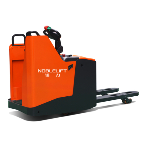
Noblift SPT15 Series Datasheet

△
!
WARNING
Do not use the stacker before
reading and understanding this
operating instructions.
NOTE!
Keep for future reference.
Chinese well-known trademark
National inspection-exempted product
Operating Instructions / Parts List
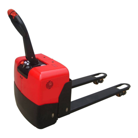
SPT15 Power Pallet Truck

Foreword
Welcome to choose our SPT15 series power hydraulic pallet truck. You should be an expert for
operating this truck after you carefully read and understand this manual thoroughly.
This Operation Instruction is edited for you to completely acquire and master the safety operation,
main technical parameter, maintain methods and parts list for the pallet truck
Several icons show you as follow, they stand for different meanings:
1. ---- Safety instructions that you must abide by before operation, if not do so, it should lead
to injury of man or damage of equipments and fire.
2.△
! ---- Regulations that you need to pay attention and have to comply with before operation, if
not do so , it should lead to damage of equipments or some sort of injury of man.
3. ---- Something that you have to pay attention before operation.
△
! The majority of materials that consists of the equipment can be completely recycled. During
the working, repairing, maintenance and cleaning, there are some waste materials being produced.
These waste materials have to be collecting and disposing in a friendly-environment way under the
rules of local government. Professional experts may be necessary for dealing with these waste
materials ( such as oil leakage, old battery and waste equipments) at a specified area, otherwise,
the negative effect and damage should take place for environment and human health.
All of the information reported herein is based on data available at the moment of the
publication of the manual. Our products are constantly being developed and renewed, we reserves
the right to modify our own products at any moment without notice or incurring in any sanction. So, it
is suggested that you may be always to pay attention to possible updates.
1

1 Safety Operation Regulation
1.1 Operator should be qualified
The pallet truck must be operated by trained person, who can demonstrate moving and operating
the pallet truck to user and can definitely instruct the user how to operate the truck.
1.2 Right, obligation and responsibility of operator
The operator must fully understand his right and obligation and had already received the training of
the pallet truck operation. At the same time, the operator must master the related descriptions in
Operation Instruction. In case of the pallet truck steered by the method of walking control , the
operator should wear safety boots.
During operation, the operator must be responsible for the pallet truck and prevent unauthorized
person from driving or operating the pallet truck. The pallet truck is strictly forbidden to lift or carry
person.
1.3 Failure and fault
In case of any failure or fault occurring, please notify the administrative managers immediately. In
case that pallet truck can not work safely (such as wheel worn-out or brake fault), please stop using
the pallet truck until they are properly repaired
1.4 Repair and maintain regulation and environment protection
Without professional training and specific authorization, the operator is forbidden to repair or change
any part of the pallet truck . Any change of installation position of switches and safety devices is
strictly forbidden for operator to avoid efficiency decrease of the pallet truck.
△
! All spare parts from original manufacturer are qualified by Quality Assurance Authorities. To
ensure the safety and reliability of pallet truck operation, only the spare parts from the manufacturer
can be applied. The used-parts, including used-oils and used-fuels, must be disposed according to
related environmental protection regulation.
1.5 Danger area
Danger area refers to: the area where the pallet truck or its lifting device (such as fork or
attachments) is working or lifting, which brings potential danger factors to person; or the area where
the goods was being transported. Generally speaking, the range of danger area include the place in
witch the load was lowering or the pallet truck attachment was lowering.
Unauthorized person must be kept away from danger area. If there is any potential danger may
be to damage people, the operator must give warning signal, If someone still stays in danger area
while being requested to leave, the operator must stop the pallet truck immediately.
1.6 Work in high risk environments
If the pallet truck have to be working in the high risk area, it is necessary that equip some special
2

devices witch aim to protect the operator and the equipment from the danger,for example, when the
pallet truck working in a oil-house, the anti-static devices must be equipped.
△
! This pallet truck is designed for normally work environment only !
1.7 Driving in public areas
The pallet truck is forbidden for driving on the public road except the specified area.
1.8 Distance between vehicles
Remember that the vehicle it is running in front of you may brake suddenly. Keep a reasonable
distance please.
1.9 Driving into elevator and operating at loading platform
The pallet truck may only be driven into an elevator or operated at a loading platform if it has been
authorized. The elevator and loading platform should be having enough load capacity and where
there wasn’t any hamper for operation and the permission of pallet truck user should also be
necessary . The operator must confirm this matter before getting into elevator or loading platform.
The cargo should be placed in front of the pallet truck and the pallet truck should take a proper
occupancy of position when the pallet truck enters elevator in order to avoid touching the walls of
elevator. If the elevator be used by loading both pallet truck and passengers simultaneously,
passengers must enter the elevator after the pallet truck and walk out of the elevator before the
pallet truck.
The total weights = weight of vehicle + weights of goods
1.10 Operation management
Driving speed must be applicable for local condition. Low speed is requested for swerve driving,
narrow aisle passing, swing door passing or driving in blocked field. The operator must be capable
to measure the stop distance ahead to pallet truck by sight and get on top of his driving. Sudden
braking (except in emergency), quick U-turn and overtaking in blocked field are prohibited.
1.11 Visibility The operator must stare at driving direction to ensure legible sight for the road
condition ahead. In case that cargo carried interrupts the sight, reverse driving is requested. If it
doesn’t help in this way, there must be another person walking ahead of pallet truck to give
guidance and warning.
1.12 driving on slopes and inclines
Can only the recognized slope and inclines be permitted for pallet truck passing through, while the
technical criterion of Operation Instructions also permits that. The cargo carried must face to upward
direction of the slope. U-turns, driving obliquely over slopes or inclines and parking on slopes or
inclines is prohibited. When passing slopes or inclines, the pallet truck should be driven at slower
speed. At the same time, the operator must prepare for braking at any moment
3

1.13 Parking safety
The parking safety is necessary. The pallet truck have to be parked on the qualified area witch is
level and solid. Prohibit parking the vehicle at the slope or the inclined plane. The forks must be
lowered to the lowest position after working, so no accident occurring when the fork dropping
suddenness.
1.14 Signaling for warning
You should use the truck horn to give a signal to attract attention.
1.15 Protective shoes
Protective shoes should be worn when working with pallet truck according to EU standard
EN-345:1-S1.
4

2 Technical Specifications
SPT15 series power pallet truck is a new product designed on the base of normal hydraulic pallet
truck. It’s maximum load weight is 1500 Kg; the one of the merits of this product is motor drive
without manpower for pushing or drawing of the pallet truck, this matter is absolutely evidence
when working under hard working condition.
2.1 Technical Features
1.2 Model of manufacture SPT15
1.5 Capacity / rated load Q K g 1500
1.6 Load centre distance C m m 600
1.8 Load distance X mm 938
Characteristics
1.9 Wheelbase y mm 1275
2.1 Weight (including battery) Kg 160
Weight
Tyres (rubber, Vulkollan, pneumatic, polyurethane) polyurethane
3.2 Tyre size drive end mm Φ220×70
3.3 Tyresize loadend mm Φ80×70
3.4 Castor wheels (dimensions) mm Φ50×30
Wheels types
3.5 Wheels, number(x=drive wheel) drive end / load end 1x -2 / 4
4.2 Overall height h mm 1310
4.4 Lift height h max mm 200
4.15 Minimum fork height hmin mm 85
4.21 Overall width b1mm 540
4.22 Fork dimension s/e /l mm 48 / 160 / 1150
4.25 Overall fork width b5mm 540
4.32 Clearance between fork-base and ground m 2mm 38
4.34 Working aisle with 800x1200 pallet lengthwise Ast mm 1895
Dimensions
4.35 Outer turning radius Wa mm 1430
5.1 driving speed full load / without load Km / h 3.0 /3.3
5.8 Gradeability full load / without load % 5 / 8
Performance
5.10 brake electric
6.1 Driving motor power W 400
6.4 Battery voltage/capacity V / Ah 2x12 / 40
6.5 Battery weight +/-5% Kg 20
Electric motor
Box dimension of battery (length /width/height) mm 197 / 165 / 174
5

2.2 Technical standard
Durative noise level must be < 70dB(A); Refer to ISO4871 Standard
The continuous noise level (the sound pressure level) is a value averaged that is measured
according to standard regulations during the truck was driving , lifting, and idling. The point where
the sound pressure level is measured is at the ear.
Electromagnetic Compatibility (EMC)
Manufacturer confirms that the vehicle meets the requirement of the limit values for electromagnetic
emission and interference immunity, according to EN12895 and the related standards contained
therein. the testing of static electricity discharge also has been made.
Any change or replace for parts in electrical system should be done only when there is the
written approval issued by the manufacturer.
2.3 Work temperature
Work temperature: 5℃~40℃
If the temperature is below 5℃or the air is the higher humidity, the special protections should
be taken by using some certain instruments.
6

3 Transportation and Commissioning
3.1 packing and delivery
△
! The pallet truck is packed by wooden material and it can be loading or unloading by crane or
forklift.
3.2 assembling handle
You need some kind of tools, such as a hammer, a pliers, etc. some more, you also need sort of
fittings, such as a bored-shaft, two elastic pin (remarks: the one of the two have already assembled
on the bored-shaft, these two fittings have been put into a plastic bag, the bag has been bound to
the handle by adhesive tape )
1. handle 2. pin 3. bored-shaft 4. elastic pin 5. vehicle frame
When attaching the handle, you had better squat just behind the pallet truck. Then you:
3.2.1 Insert the draw-bar onto the pump piston (120), then use a hammer to insert the axle with hole
7

(206) into the hydraulic pump and draw-bar from the right to left.
2.2 Let control handle(217) to the ‘LOWER’ position, then pass the
adjusting nut(207), adjusting bolt(208) and chain(209) through the
hole of axle(206) with your hand.
3.2.3 Press the draw-bar (211) down, take away the pin(#2).
3.2.4 Let the control handle (217) on ‘RAISE’ position, then raise the lever plate (109) with the pin
(#2) and insert the adjusting bolt(208) into the front slot of lever plate (109), note to keep the
adjusting nut (207) on the under side of the lever plate.
3.2.5 Use a hammer to tap another elastic pin (205) into the axle with hole (205).
The draw-bar is now assembled to the pump.
3.3 Adjusting Release Device
On the draw-bar of this pallet truck, you can find the control handle(217) which can be adjusted in
three positions :
Raise -handle down
Drive -handle in center position
Lower -handle up, the lever moves back the drive position when released.
If however they have been changed, you can adjust according to following step:
3.3.1 If the forks elevate while pumping in the DRIVE position, turn the adjusting nut (207) on the
adjusting bolt(208) or screw(111) clockwise until pumping action does not raise the forks and the
DRIVE position functions properly.
3.3.2 If the forks descend while pumping in the DRIVE position, turn the nut(207) or screw(111)
counter-clockwise until the forks do not lower.
3.3.3 If the forks do not descent when the control handle (217) is in the LOWER position, turn the
nut(207) or screw (111) clockwise until raising the control handle(217) lowers the forks. Then
check the DRIVE position according to item 3.1 and 3.2 to be sure the nut (207) and screw(111)
is in the proper position.
8

3.3.4 If the forks do not elevate while pumping in the RAISE position, turn the nut (207) or screw
(111) counter-clockwise until the forks elevate while pumping in the RAISE position. Then check
the LOWER and DRIVE position according to item 3.1, 3.2 and item 3.3.
3.4 Electric wiring for handle
①find the end of the wire from guard shield;
②connecting both plug and socket from power
wire and handle wire;
③coordinating different wire in a clear and tidy
condition, fastening it, so, until now, the work
is done.
3.5 Battery assembling
①demount the shields of charger and battery in
sequence by screwdriver;
②moving the battery to close the body of vehicle,
drawing out the end of the connection of the battery;
screw off the plastic cover and the bolt of the battery;
③connecting anode to B+, cathode to B-, also connecting between anode and cathode of the
battery, cover connection and screw bolt on .
④Remove the battery slowly, put the battery into box gently, tidy up wires.
⑤Finally, assembling the shield of battery and charger. Now the work is done.
9

4 Operation Instructions
4.1 Driving handle
4.1.1 Control handle: it has three position, Raise, Drive and Lower, (See 3.3), control the fork
down and up.
4.1.2 FWD-BWD Tuning Knob: Control the speed of the stacker and moving direction: forward or
backward.
4.1.3 Horn button
4.1.4 Reversing switch: the emergency directional reverse button
4.1.5 Power switch: On / Off the power of the control circuit.
4.2 Starting up of Truck
The operator must confirm no persons staying in the danger area before starting and operating
the truck or lifting cargos.
Routine Checking before Starting up
Check if any external truck defects (especially wheels and pallets)
Check if battery fixed firmly and cable connected properly
Truck starting up
Turn on Power switch.
Battery capacity meter indicates the current capacity
Check the function of horn
Check the braking function of control handle
Now, the preparation before starting up of the truck is completed.
10

4.3 The Truck Operation
4.3.1 Operation of Starting up, Driving and Parking
Enough caution must be attached for starting up and driving of the truck, especially when the
person body reaching out of the truck. Make sure that during driving, it is prohibited to carry any
person.
Emergency parking
When parking urgently, press power switch and then all electric control functions are cut off and let
the handle-bar be vertical.
Forced braking
If you are forced to stop, release the handle-bar, let it be vertical, and then the truck is automatically
braked (emergency stop).
Starting up
The driving speed is controlled by the controller.
Pull down the handle-bar to a befitting position.
Adjust the handle-bar to the direction required and the truck is moving towards the selected
direction.
Driving
Swing the FWD-BWD Tuning Knob leftwards or rightwards to drive.
Driving on a Slope
The cargo carried must face to upward direction of the slope. Make sure to take safety
measures to the downward slip direction of the truck: When the FWD-BWD Tuning Knob at “0”
position, please pull the handle backwards immediately and release it according to actual
requirement to enable the electromagnetic brake to work automatically and control the speed and
the direction of the truck (for downward slip).
Braking
The operator must fully understand the braking performance is subject to the road conditions.
But there are three braking types for the truck:
Electromagnetic braking (handle-bar)
Reverse current braking (controller)
Sensor braking (release braking)
Electromagnetic braking
In emergency situations, the truck must be stopped by electromagnetic braking (handle-bar be
vertical) only.
11

L
After releasing the handle-bar, it will be vertical automatically.
et the handle-bar be vertical, the driving motor is stopped mechanically.
After parking of the truck, the electromagnetic braking takes the function of park braking.
Reversing current braking
In case of control system or driving power malfunction, it is possible to use reverse braking.
Rotate the FWD-BWD Tuning Knob against the direction of driving until the truck is stopped.
Then release the FWD-BWD Tuning Knob.
Inertia braking
After releasing the FWD-BWD Tuning Knob, it returns back to “0” position and the truck is
stopped by motor inertia. Noting that the ratio of speed reduction is subject to the position of
the FWD-BWD Tuning Knob.
If inertia braking is removed by maintenance staff and the FWD-BWD Tuning Knob is set at
“0” position, the truck can be stopped only by electromagnetic braking and reverse current braking.
4.3.2 Operation of cargo loading/unloading
Before loading the cargo, the operator must check to confirm the cargo is properly placed on
the pallet and the weight of cargo within the load capacity of the truck. Remember that carrying a
cargo in full load for a long time is prohibited.
The forks should extend to the bottom of the cargo completely.
Let the control handle(217) be Raise or Lower position when you want to lift or lower the
cargo.
Lifting of forks
Let the control handle(217) be Raise position, then move the handle-bar up and down.
Lowering of forks
Let the control handle(217) be Lower position, the fork will be down automatically.
12

5 Maintaining, Charging and Replacing the Battery
5.1 operation safety regulation of battery
Before any operation on the battery, you should park the vehicle stably and safely.
5.1.1 maintenance staff
The operation of charge, repair and replacement of battery should be performed by qualified
professionals. Before operation, read the instruction carefully including operation manual,
requirement for supply preparation and charge.
5.1.2 Fire protection
During operation of battery, smoking and ignition are strictly forbidden in the working field. When
storing and charging the battery, you should keep flammable substance away at least 2m distance.
Choose a airy place with fire protection equipment to store the battery.
5.1.3 Maintenance of battery
1) Keep each nut from every battery dry and clean. Each connecting terminal and cable terminal
should be tightened and painted with clean grease to avoid eroding. The exposed connecting
terminal and connecting rod of battery should be covered with anti-slip insulated cover.
2) The connecting lines between cells should be in good contact. Check nuts if loosening or sliding,
If so, fasten it.
3) Keep the surface of the battery clean and dry.
4) Over-charge and over-discharge should be avoided for battery, and forcefully charging or
undercharging is strictly prohibited, or, its life-span will be shortened.
5) Conductive objects are not permitted to be placed on the battery (including metal tools) In order to
avoid shortening life-span of battery, otherwise, it can lead to short circuit, or , even explosion
6) No harmful substance of solid or liquid is allowed to be dropped onto the surface of the battery.
When the densitometer or thermometer is used, its surface should be clean.
7) After battery is utterly discharged, they should be recharged in time (delay of time for charging
should lead to damage of the battery). Maximum charging intervals should not exceed 24 hours
( On very cold day, if battery can not be charged, it should be placed indoor for charging.)
8) If the battery do not be used for a long time, it should be full charged once a month for every
month.
9) During the charging, ventilation equipments should be provided, and smoke / fire should be
forbidden, in order to avoid hydrogen explosion.
13

5.1.4 Disposal for old battery
Old battery must be recall or deposit at the safe-environmental area or special disposal area
appointed by the local government, the department that dispose these scrap should be authorized. .
As the electrolyte in battery is poisonous and corrosive, the man who operate the battery
should be performed in overall and protection goggles to avoid body touching the acid solution of
the battery.
△
! In case that acid solution touches clothes, wash it immediately with plenty of water. If the skin
or eye touch the acid solution, you should be not only washing with plenty water but also going to
hospital immediately. The acid extravasations should be eliminated through neutralization
treatment.
5.2 Type of Battery
The weight and the dimension of the battery can be known from the battery nameplate.
△
! During replacement or assembly of battery, make sure the battery fixed in the case reliably.
5.3 Battery indicator
Battery capacity meter: Discharging value of battery is indicated on battery capacity meter, it has
ten indicator bars that each one has 10% increase in sequence.
With the consumption of battery capacity, the bright bars will descend downwards from the top.
The mark of “Alarm” will appear when: The residual capacity of the battery against normal battery at
the 30%. Now the battery is needed to charge.
Capacity Sufficient Charge Required Capacity Insufficient
5.4 Charge of Battery
△
! the battery witch is non-use for a long time should be charged. Charge of battery must comply
14

with instruction manuals provided by battery supplier and charger supplier.
During charge course of battery, keep airy condition. Before charge, make sure no metal object on
the battery and check up if there is any obvious fault on joints of the all of the cables and plugs. The
safety instructions, including the requirement for supply battery and the preparing of charging
battery, should be abided by strictly.
The course of automatically charging: the battery charger is built-in, automatically operation and
intellectual ability. You only need to connect between charger and electric power, the charger will
automatically adjust the volume of current according to capacity witch is retained in the battery to
keep the operation in a best state. After finishing the charging, the charger will stop charging and
cut off electric power automatically. There are 8 or 10 hours to be needed for a charging course.
5.5 replacement for battery
If the battery is failure for use, you have to replace it immediately,you need to disassemble the
battery according to the contrary course of the “3.5 battery assembling”.
15

6 Maintenance instructions
Daily maintenance for this SPT15 series semi-electric hydraulic pallet truck is necessary.
6.1 daily checking and maintenance
6.1.1 Hydraulic oil: once every six month for oil level checking. gross oil volume is 0.3 liter. Choose
the hydraulic oil according to the form as bellow:
temperature hydraulic oil
-20 ~+40℃℃ L-HV46 hydraulic oil
6.1.2 Exhausting air: The air may come into the hydraulic oil because of transportation or pump in
upset position. It can cause that the forks do not elevate while pumping in the RAISE position. The
air can been removed in the following way: let the control handle (217) on the LOWER position,
then move the draw-bar up and down for several times.
6.1.3Lubrication: before delivery, all of the bearings and shaft pole have been placed with enduring
lubrication oil, so, you need maintain it with lubrication oil only once every month or after every
cleaning it.
6.1.4 Maintenance: the daily maintenance for this semi-electric hydraulic pallet truck can increase
the life span of the vehicle. Wheels and wheel shafts should be careful of checking for if it is wound
by cotton thread or rags etc.. after operating, you have to unload the goods on the forks and then
lower the forks to the lowest position.
the operator should maintain the vehicle every day as bellow steps:
1 check up if it is leaking of oil
2 check buttons and switches
3 check tummy button
4 check horn
5 check up travel switch of the control handle
6 check wheels and forks
7 check charger
16

6.2 Fault diagnosis
No. fault cause results
1 -the forks cannot
reach the
highest position
- the hydraulic oil is not enough - add hydraulic oil
2 Forks cannot
lift
- without hydraulic oil
- impure hydraulic oil
- Adjusting nut (207) is too high or
adjusting screw (111) too close,
result in opening the release valve
- there are air in hydraulic oil
- add hydraulic oil
- replace hydraulic oil
- repeat to adjust the nut (207) or
adjusting screw (111) (refer to 3.3)
- exhausting air
3 Forks cannot
lower
-big piston (118) or pump body
(112) is damaged because
overload or goods is eccentricity
put
- Big piston rod get rust because
fork stay at a high position for a
long time.
-Adjust nut (207) or screw (111) is
in the wrong position.
- Replace big piston rod (118) or oil
pump body(112)
- lower the fork to the lowest position
and lubricating the piston rod in time.
-Repeat adjust nut (207) or screw
(111) (refer to 3.3)
4 oil leakage - seal washer is old or damage
- some components is broken
- renewed
- renewed
5 forks lower
from itself
- impure hydraulic oil result in
release valve cannot close
- some parts in hydraulic system
is broken or damage
- air enter hydraulic oil
-seal washer is over-used or
damage
- nut(207) or screw(111) is not in
the correct position
- replace hydraulic oil
- check and replace
- exhausting air (refer to 6.1.2)
- replace
-readjust nut (207) or screw (111)
(refer to 3.3)
6 cannot forward
or backward
- accelerator fault
- wire is old or damage
- replace accelerator
- renew electric wiring
7 horn button is
failure
- spring is failure
- wiring is old or damage
- replace spring
- renew electric wiring
17

7 ELECTRICAL DIAGRAMS
7.1 CIRCUIT DIAGRAM
7.2 CONNECTION DIAGRAM
18

7.3 Layout for electronic components
No. Description qty. remarks
1 drive wheel 1 91L-DC 0.4KW/24V
2 bolt 4
3 screw 1
4 contactor 1 HZBD-80/24
5 fuse 1 60A
6 nut 2
7 screw 2
8 fuse base 1
9 rectangle electric meter 1 24V
10 screw 2
11 screw 4
12 Built-in charger 1 QQE192-4CH12-B
13 battery 2 6-DM-38
14 screw 2
15 alarm buzzer 1
16 controller(SHIN20)1 XS2243-6100
17 screw 3
19
Table of contents
Other Noblift Truck manuals
