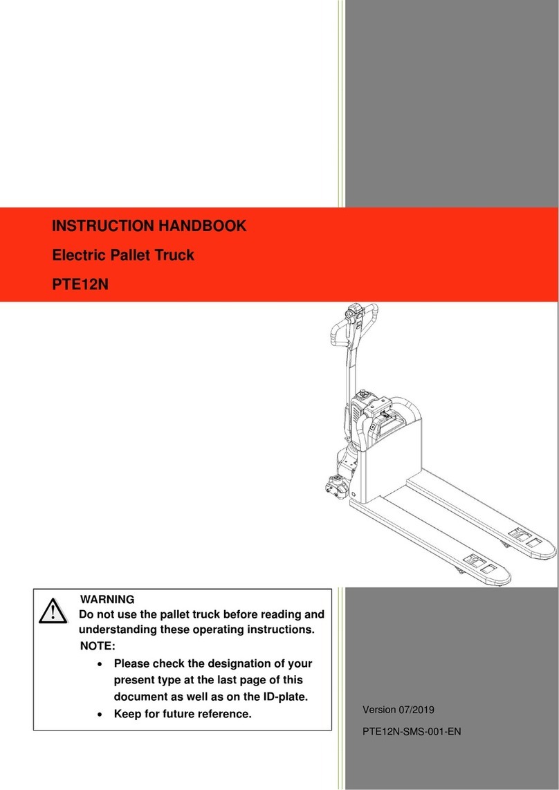
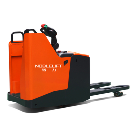
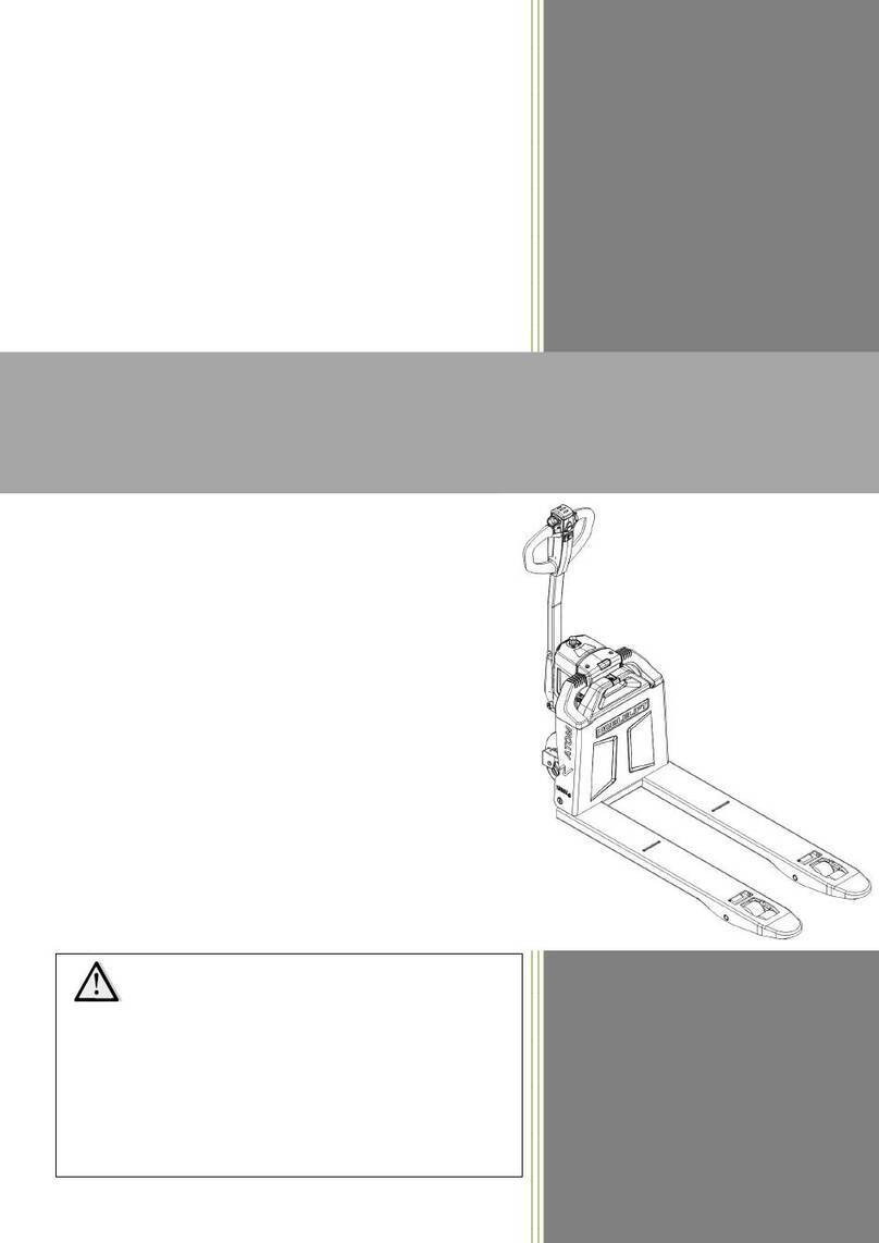
Noblelift FE3P16-35 N User manual

重诺力行 物动随心
诺力智能装备股份有限公司
地址: 浙江省长兴县太湖街道长州路 528 号
咨询热线: 4001-603611 售后热线:4008-836115 传真: 0572-6212851 邮箱: info@noblelift.com
www.noblelift.cn 物料搬运·系统集成
1
FE4P16-35N-SMS-001
WARNING
Do not use the forklift before reading and understanding the operating
instructions as well as the warning decals on the truck.
Keep for future reference.
Service & Maintenance Manual
FE3P16-35 N Battery counterbalanced forklift truck
NOBLELIFT INTELLIGENT EQUIPMENT CO.,LTD.

重诺力行 物动随心
诺力智能装备股份有限公司
地址: 浙江省长兴县太湖街道长州路 528 号
咨询热线: 4001-603611 售后热线:4008-836115 传真: 0572-6212851 邮箱: info@noblelift.com
www.noblelift.cn 物料搬运·系统集成
2
Content
Safety…………………………………………..………………………………………………………………………………………………..…4
General Safety ……………………………………………………………………………………………………………………………….4
Maintenance………………………………………………………………………………………………………………………………….4
Drive system and brake system.…………………………………………………………………………………………………….….5
Steering system………………………………………………………………………………………………………………………………..7
Overview……………………………………………………………………………………………………………………………………….7
Inspection of the steering cylinder and steering system after reinstallation…………………………………11
Hydraulic system……………………………………………………………………………………………………………………………..12
Schematic ……………………………………………………………………………………………………………………………………12
Main oil pump………………………………………………………………………………………………………………………………13
Multi-way valve……………………………………………………………………………………………………………………………13
Priority valve………………………………………………………………………………………………………………………………14
Multi-way valve pressure adjustment.…………………………………………………………………………………………14
Shutoff valve………………………………………………………………………………………………………………………………15
Govern valve………………………………………………………………………………………………………………………………16
Lifting cylinder, tilting cylinder sketch (with seal ring and other models).……………………………………..16
Lifting system……………………………………………………………………………………………………………………………………25
Overview………………………………………………………………………………………………………………………………………25
Adjustment of the lifting system.………………………………………………………………………………………………….25
Standards for inspection and replacement of forks..……………………………………………………………………27
Regular inspection and maintenance……………………………………………………………………………………………….27
1. Checkpoints and inspection contents……………………………………………………………………………………..28
2. Checking programmer…………………………………………………………………………………………………………….30
3. Check after operation…………………………………………………………………………………………………………..32
4. Cleaning ……………………………………………………………………………………………………………………………….32
5. Regular maintenance schedule………………………………………………………………………………………………34
6. Regular replacement of critical safety parts.…………………………………………………………………………..43
7. Lubrication parts and recommended oil…………………………………………………………………………….…..43
8. Maintenance Record Form……………………………………………………………………………………………….…..45
Electrical System….……………………………………………………………………………………………………………………….…46
4.1Electronic Control System (Inmotion)…………………………………………………………………………………46
Schematic…………………………………………………………………………………………………………………………………….47
Main functions and settings..………………………………………………………………………………………………………47
Electrical System Maintenance…………………………………………………………………………………………………..48
Integrateded meter………………………………………………………………………………………………………………………48
Failure Analysis…………………………………………………………………………………………………………………………..49
4.2Electric Control Assembly (Curtis)………………………………………………………………………………………….54
Schematic diagram of the electrical system………………………………………………………………………………....55
Main functions and settings……………………………………………………………………………………………………….55

重诺力行 物动随心
诺力智能装备股份有限公司
地址: 浙江省长兴县太湖街道长州路 528 号
咨询热线: 4001-603611 售后热线:4008-836115 传真: 0572-6212851 邮箱: info@noblelift.com
www.noblelift.cn 物料搬运·系统集成
3
Maintenance of electrical systems.…………………………………………………………………………………………….56
Integrated meter……………………………………………………………………………………………………………………..…57
Failure Analysis.………………………………………………………………………………………………………………………..…57
Failure case analysis and solution…………………………………………………………………………………………..…..63
Key position torque diagram…………………………………………………………………………………………………………68

重诺力行 物动随心
诺力智能装备股份有限公司
地址: 浙江省长兴县太湖街道长州路 528 号
咨询热线: 4001-603611 售后热线:4008-836115 传真: 0572-6212851 邮箱: info@noblelift.com
www.noblelift.cn 物料搬运·系统集成
4
Safety
General maintenance rules
To ensure safety, when jacking up the vehicle, the vehicle should be parked on a level surface
and the front and rear wheels in a braking state.
After the vehicle is supported on the chassis frame, the support point is pressed against the axle
and the frame by the jack, the vehicle is jacked up and maintenance work is performed.
Before performing maintenance work, remove the battery to avoid wire damage and burnout
caused by short circuit.
The body, seat and floor should be covered with a protective cover to prevent damage and
contamination.
Brake fluid can easily damage the paint surface, so be careful when handling
Use the prescribed tools and special tools.
Use Noblelift original accessories.
Used cotter pins, gaskets, O-rings, oil seals, lock washers and self-locking nuts must be discarded
and new ones should be prepared for reassembly. If these parts are reused, they will not
guarantee normal function.
In order to ensure the correct and smooth reassembly work, the disassembled parts should be
neatly grouped and stored.
Parts should be legible before inspection and reassembly. In addition, the oil port should be
purged with compressed air to confirm that these parts are not blocked.
Prior to assembly, the rotating and sliding surfaces of the parts must be lubricated with oil or
grease.
If necessary, sealant should be used on the gasket to avoid leakage.
To fully understand the torque specifications of all bolts and nuts.
When the repair work is finished, be sure to check that the repair work is performed correctly.
Maintenance
Please use a jack or a stop. Confirm the surrounding safety conditions. The rope used to lift
heavy objects must have a sufficient safety factor. Before using a power tool to remove parts,
make sure the bolts, nuts, tubes, and harness are completely separated.
When transporting heavy items, use certain equipment or tools and do not move them by hand.
When servicing hydraulic systems and other dust-proof components, use clean tools and work in
a clean, dust-proof area.
Before servicing or soldering electrical system components, be sure to remove the battery
terminals.
Take care to prevent oil, gas and flammable materials from entering the work area. Organize the
broken parts and tools.
A warning sign is hung on the joystick during maintenance.
Do not stand directly under the fork or fork. Use the stop to block the equipment and the fork
frame during maintenance.
The repair tools are placed in order, checked regularly, and used correctly.

重诺力行 物动随心
诺力智能装备股份有限公司
地址: 浙江省长兴县太湖街道长州路 528 号
咨询热线: 4001-603611 售后热线:4008-836115 传真: 0572-6212851 邮箱: info@noblelift.com
www.noblelift.cn 物料搬运·系统集成
5
Drive system and break system
4P-N series counter balance forklift ‘s gearbox and drive axle
16-18N
20-25N
No. Name Qty No. Name Qty
1 Housing 1 11 Hub 2
2 Blocking 3 12 Breaking hub 2
3 Half shaft 2 13 Hub connecting bolt 12
4 Half shaft seal
washer
2 14 Bearing 30213E 2
5 Hub connecting
bolt
16 15 Bearing 2
6 Nut 4 16 Oil seal SG100*125*12 2
7 Washer 2 17 Brake bolt 4
8 Spacer 5 18 Brake bolt M14*1.5*40 12
9 Bearing 33012A 2 19 Left brake assembly 1
10 Rim nut M14*1.5 12 20 Right brake assembly 1
21 Air hole assembly 1
No. Name Qty No. Name Qty
1 Left brake assembly 1 13 Bearing 30615 2
2
Drive axle left
bearing plate
1 14 Bearing 33115 2
3 Air hole assembly 1 15 Nut seat 2
4 Blocking 3 16 Nut seat criclip 2
5 Drive axle housing 1 17 Spring washer 6 4
6 Oil seal SD45*62*12 2 18 Bolt M6*12-4.8 4
7
Drive axle right
bearing plate
1 19 Hub 2
8
Right brake
assembly
1 20 Hub connecting
bolt
12
9 Spring washer 14 16 21 Half connecting
bolt
2
10 Brake bolt 4 22 Half shaft seal
washer
1
11 Brake bolt 12 23 Rim nut 12
12
Oil seal
SD100*140*12
2

重诺力行 物动随心
诺力智能装备股份有限公司
地址: 浙江省长兴县太湖街道长州路 528 号
咨询热线: 4001-603611 售后热线:4008-836115 传真: 0572-6212851 邮箱: info@noblelift.com
www.noblelift.cn 物料搬运·系统集成
6
30-35N
Troubleshooting
Trouble Cause Method
Noise
Loose bolts connecting the
drive axle to the frame
Fastening
Loose rim bolt Fastening
Wear or damage to bearings in
the hub
Replace
Half shaft spline is worn Replace
Lack of lubrication Refuel
Unstable Drive Loose rim bolt Fastening
Wheel deformation Replace
Wear or damage to bearings in
the hub
Replace
Wear or damage to bearings in
the hub
Fastening
Wrong tire pressure Adjusting
Drive axle maintenance
Apply grease to the tapered roller bearing. When tightening the tapered roller bearing lock nut in the
hub, it should be noted that after tightening, turn the hub forward and backward for 2~3 turns.
Check whether the torque of the wheel meets the standard. The torque of the hub is 9.8~29.4NM.
The tightening torque of the semi-axle mounting bolt is 96~111NM. The tightening torque of the
wheel nut is 470~550NM. The tightening torque of the bottom plate mounting bolt is 210~230NM.
No. Name Qty No. Name Qty
1 Left brake assembly 1 13 Bearing 30615 2
2 Drive axle left bearing
plate
1 14 Bearing 33115 2
3 Air hole assembly 1 15 Nut seat 2
4 Blocking 3 16 Nut seat criclip 2
5 Drive axle housing 1 17 Spring washer 6 4
6 Oil seal SD45*62*12 2 18 Bolt M6*12-4.8 4
7
Drive axle right
bearing plate
1 19 Hub 2
8 Right brake assembly 1 20 Hub connecting
bolt
12
9 Spring washer 14 16 21 Half connecting
bolt
2
10 Brake bolt 4 22 Half shaft seal
washer
1
11 Brake bolt 12 23 Rim nut 12
12 Oil seal SD100*140*12 2

重诺力行 物动随心
诺力智能装备股份有限公司
地址: 浙江省长兴县太湖街道长州路 528 号
咨询热线: 4001-603611 售后热线:4008-836115 传真: 0572-6212851 邮箱: info@noblelift.com
www.noblelift.cn 物料搬运·系统集成
7
Drive axle and frame connection bolt replace precautions
When the drive axle and the frame connecting bolt are replace, the screw fastening rubber is used
for relaxation. When the drive axle and the workshop connecting bolt are loosened and the drive axle
is re-installed, the adhesive layer attached to the bolt should be cleaned, and the thread glue drops a
few drops to the thread. Engagement and tighten to the specified torque
Steering system
Technical data
Model Real axle Turing with power steering
Steering wheel
Cycloid type hydraulic
steering gear
16-18N BZZ5-E80BCF-H6
20-35N BZZ5-E100BCF-H6
Steering bridge Type Central winch support
Turing angle 80°inside wheel, 55°outside wheel
Wheel bearing load The torque of the hub is 2-10NM
Wheel Type 16-18N 5.00-8-10PR
20-35N 18*7-8-14PR
Pneumatic
tire pressure
Overview
The steering system consists of a steering wheel, a pipe string, a coupling shaft, a steering gear, a
mounting bracket and a steering axle.
Steering mechanism
The steering bracket, the pipe string and the coupling shaft are coupled together by the mounting
bracket, and the steering gear is fixed at the lower end of the coupling shaft. The rotation of the
steering wheel will drive the steering gear to rotate, and the diverter valve is measured according to
the angle of the steering wheel rotation. The pressure oil is transferred to the steering cylinder
through the hydraulic hose. The steering wheel can be adjusted to the comfort position felt by the
driver by adjusting the handle.
Steering cylinder
The steering cylinder is a double-acting through type. The piston rod is driven by the gear and the
steering shaft. The pressure oil from the hydraulic steering gear moves the piston rod to the left and
right through the steering cylinder to realize the steering.
Steering bridge structure diagram see drawing

重诺力行 物动随心
诺力智能装备股份有限公司
地址: 浙江省长兴县太湖街道长州路 528 号
咨询热线: 4001-603611 售后热线:4008-836115 传真: 0572-6212851 邮箱: info@noblelift.com
www.noblelift.cn 物料搬运·系统集成
8
16-18N
No. Name Qty No. NameQty No. Name Qty
1
Steering bridge
assembly
1 15 Washer GB97.1-12 4 29 Nut M12*40 4
2 Linking rod 2 16 Bearing 30208 2 30 Washer GB93-12 4
3
Steering cylinder
assembly
1 17 Bearing 30206 2 31 O ring 2
4 Anti-vibration pad 2 18 Nut M24*2 2 32 Oil seal 4
5 Fixing plate 2 19 Washer GB97.1-24 2 33 Bushing Φ26* Φ
24*6.5
4
6
Left Knuckle
assembly
1 20 Pin 5*45 2 34 Bolt M12*40-8.8 2
7 Bearing 2 21 Wheel hub cover 2 35 Grease nipple(90°)2
8 Bearing 942/25 2 22 Steering wheel hub 2 36 Nut M16 4
9 Pin 2 23 Pin 2 37 Bolt M16*45-8.8 4
10 Dowel pin 8*20 2 24 Nut GB6170-M10 2 38 Washer 16 4
11 Circlip 8 25 Washer GB97.1-10 2 39 Linking pin 4
12 Y seal ring 2 26 Bushing 2 40 Bearing GE1515ES 4
13 Pad 4 27 Grease nipple 4
14 Nut GB6170-M10 12 28 Right knuckle assembly 1

重诺力行 物动随心
诺力智能装备股份有限公司
地址: 浙江省长兴县太湖街道长州路 528 号
咨询热线: 4001-603611 售后热线:4008-836115 传真: 0572-6212851 邮箱: info@noblelift.com
www.noblelift.cn 物料搬运·系统集成
9
20-35N
No.
Name
Qty
1 Piston rod assembly
1
2 Cylinder cover 2
3 Dust ring DH40 2
4 U ring UN40 2
5 O ring 53*3.55 2
6 O ring 50*3.55 1
7 Support ring 1
8 Cylinder assembly 1
9 Bearing 2

重诺力行 物动随心
诺力智能装备股份有限公司
地址: 浙江省长兴县太湖街道长州路 528 号
咨询热线: 4001-603611 售后热线:4008-836115 传真: 0572-6212851 邮箱: info@noblelift.com
www.noblelift.cn 物料搬运·系统集成
10
No. Name Qty No. Name Qty No. Name Qty
1
Steering bridge
assembly
1 15 Washer GB97.1-14 4 29 Nut M14*40 4
2 Linking rod 2 16 Bearing 32209 2 30 Washer GB93-14 4
3
Steering cylinder
assembly
1 17 Bearing 30207 2 31 O ring 2
4 Anti vibration pad 2 18 Nut M30*2 2 32 Oil seal 4
5 Fixing plate 2 19 Washer GB97.1-30 2 33 Bushing Φ26*Φ24*6.5 4
6
Left Knuckle
assembly
1 20 Pin 5*65 2 34 Bolt M14*40-8.8 2
7 Bearing 2 21 Wheel hub cover 2 35 Grease nipple(90°)2
8 Bearing 943/25 2 22 Steering wheel hub 2 36 Nut M16 4
9 Pin 2 23 Pin 2 37 Bolt M16*45-8.8 4
10 Dowel pin 10*20 2 24 Nut GB6170-M10 2 38 Washer 16 4
11 Circlip 8 25 Washer GB97.1-10 2 39 Linking pin 4
12 Y seal ring 2 26 Bushing 2 40 Bearing GE1515ES 4
13 Pad 4 27 Grease nipple 4
14 Nut M12 12 28
Right knuckle
assembly
1
No.
Name
Qty
1
Piston rod
assembly
1
2 Cylinder cover 2
3 Dust ring DH40 2
4 U ring UN40 2
5 O ring 53*3.55 2
6 O ring 50*3.55 1
7 Support ring 1
8 Cylinder
assembly
1
9 Bearing 2

重诺力行 物动随心
诺力智能装备股份有限公司
地址: 浙江省长兴县太湖街道长州路 528 号
咨询热线: 4001-603611 售后热线:4008-836115 传真: 0572-6212851 邮箱: info@noblelift.com
www.noblelift.cn 物料搬运·系统集成
11
Inspection after re-installation of steering system
Turn the steering wheel to the left and right, and check if the left and right force is even and the rotation is stable.
Check that the hydraulic piping is neatly arranged and that the left and right steering is reversed.
Lift the rear wheel and slowly turn the steering wheel left and right repeatedly several times to remove air from the
hydraulic lines and cylinders.
Troubleshooting
Trouble Cause Method
Steering wheel
locked
Oil pump damage Replace
Shunt valve blocked or damaged Clear or replace
Hose, joint damage or pipe block Clear or replace
Steering wheel
heavy to turn
Shunt valve pressure is too low Adjust pressure
Air in oil loop Release air
Steering gear reset failure, positioning spring
piece broken or insufficient elasticity Replace spring
Leakage of steering cylinder Check cylinder
seal
Vehicle swing
Steering flow is too large
Adjust the flow
rate of the
diverter valve
Spring break or no spring force Replace
Noise
Oil level low Refuel
Suction tube or oil filter plugged Clear or replace
Leakage
Steering cylinder guide sleeve seal is damaged or
pipe or joint is damaged Replace

重诺力行 物动随心
诺力智能装备股份有限公司
地址: 浙江省长兴县太湖街道长州路 528 号
咨询热线: 4001-603611 售后热线:4008-836115 传真: 0572-6212851 邮箱: info@noblelift.com
www.noblelift.cn 物料搬运·系统集成
12
Hydraulic system
Schematic
The hydraulic system consists of a main oil pump, a multi-way valve, a lift cylinder, a tilt cylinder and an oil circuit,
and the main oil pump is directly driven by the oil pump motor.
1. Oil tank
2. Oil filter
3. Pump motor
4. Gear pump
5. Priority pump
6. Steering gear
7. Multi-way valve
8. Steering cylinder
9. Govern valve
10. Shutoff valve
11. Lifting cylinder
12. Tilting cylinder
13. Oil filter

重诺力行 物动随心
诺力智能装备股份有限公司
地址: 浙江省长兴县太湖街道长州路 528 号
咨询热线: 4001-603611 售后热线:4008-836115 传真: 0572-6212851 邮箱: info@noblelift.com
www.noblelift.cn 物料搬运·系统集成
13
Main oil pump
The main oil pump is a gear pump, which is mainly composed of a pump body, a pump cover, a pair of bearings and
a sealing ring. The main oil pump adopts a load-balanced bearing and a special lubrication method to obtain a
minimum clearance of the gear end face.On one side of the starter shaft, an oil seal is mounted on the pump body
to ensure sealing performance. The seal between the pump body and the pump cover is ensured by a
special-shaped seal ring.
Multi-way valve
The multi-way valve adopts two-piece four-body type, and the hydraulic oil from the working oil pump is controlled
by the multi-way valve stem to distribute the high-pressure oil to the lifting cylinder or the tilting cylinder. There are
safety valves and self-locking valves inside the multi-way valve. The safety valve is arranged on the upper side of the
multi-way valve inlet to control the system pressure; the self-locking valve is arranged on the inclined valve plate,
which is mainly used to prevent the tilting cylinder from causing serious consequences due to malfunction of the
operating lever without a pressure source. A check valve is installed between the oil inlet port and the suction port
of the lifting valve and between the inlet port of the lifting valve piece and the oil inlet of the inclined valve piece.
The pressure of the main safety valve has been adjusted before leaving the factory, and the user is not allowed to
adjust it at will.
The pressure of the main safety valve has been adjusted before leaving the factory, and the user is not allowed to
adjust it at will.
No priority With Priority
CF
P
T
LS

重诺力行 物动随心
诺力智能装备股份有限公司
地址: 浙江省长兴县太湖街道长州路 528 号
咨询热线: 4001-603611 售后热线:4008-836115 传真: 0572-6212851 邮箱: info@noblelift.com
www.noblelift.cn 物料搬运·系统集成
14
Priority valve
The priority valve is mainly composed of a steering safety valve, a spring, a valve core and a valve body as shown in
the figure. The working principle P port is the steering pump inlet port, the CF port is connected with the steering
oil inlet port, the EF port is connected with the multi-way valve inlet port of the working system, the LS port is
connected with the steering port of the steering gear, and the T port is safe. The return port of the valve.When the
P port is filled with oil, the hydraulic oil is preferentially supplied to the CF port through the spool 3. When the
steering gear is not working, the CF port is in a closed state. At this time, the pressure of the LS port is zero, the right
end of the valve core is oiled, and the hydraulic pressure acts on the right end of the valve core to overcome the
preload of the spring 2, so that the spool moves to the left. At this time, the P port communicates with the EF port
to realize functions such as lifting, tilting, and side shifting. When the steering gear is working, the CF port is
connected to the steering cylinder via the steering gear, and the gear pump oil first enters the steering cylinder to
achieve steering.
Multi-way valve pressure adjustment
Safety valve pressure adjustment method:
The pressure of the safety valve must not be adjusted arbitrarily. If it must be adjusted, please follow the steps
below.
a) Unscrew the measuring hole screw plug at the inlet of the multi-way valve and install a hydraulic gauge that can
measure 25 MPa.
b) Operate the tilt handle to measure the pressure at which the cylinder stroke is at the end.
c) When the oil pressure is different from the specified value, loosen the lock nut of the relief valve and turn the
adjustment screw to the left and right to the specified value. When the pressure is high, turn to the left, and when
the pressure is low, turn to the right.
d) Tighten after adjustment

重诺力行 物动随心
诺力智能装备股份有限公司
地址: 浙江省长兴县太湖街道长州路 528 号
咨询热线: 4001-603611 售后热线:4008-836115 传真: 0572-6212851 邮箱: info@noblelift.com
www.noblelift.cn 物料搬运·系统集成
15
Shut-off valve
The shut-off valve is installed at the bottom of the lift cylinder to prevent the cargo from drastically falling when the
high-pressure pipe suddenly breaks. When the oil from the lifting cylinder returns to the fuel tank, it must pass
through the A hole on the outer circumference of the valve core. If the flow rate of the oil passing through the hole
is less than the set value of the valve, the pressure difference between the front and the back of the valve core is
less than the spring force, and the spool does not move and slides. The valve does not work. If the flow rate through
the spool hole exceeds the set value when the high pressure pipe is broken or for other reasons, the pressure
difference between the front and rear of the spool will be greater than the spring force to move the spool to the
left. Thus, the hole A is closed, and only a small amount of oil flows out from the small gap of the valve core and the
valve sleeve, and the cargo is slowly lowered.
锁紧螺母
盖
1) Govern valve connector
2) Spring
3) Seals
4) collar
5) Threshold
6) spool
7) Valve sleeve
8) Steel ball
9) One-way valve spring
10) valve body

重诺力行 物动随心
诺力智能装备股份有限公司
地址: 浙江省长兴县太湖街道长州路 528 号
咨询热线: 4001-603611 售后热线:4008-836115 传真: 0572-6212851 邮箱: info@noblelift.com
www.noblelift.cn 物料搬运·系统集成
16
Govern valve
The govern valve is installed in the hoisting oil line to limit the speed of the fork when it is heavy. The mechanism is
shown in Figure 5-18. When the multi-way spool valve is in the "lift" position, the high pressure oil from the
multi-way valve flows through the chambers A, B and holes C, D, E, F and chamber G without throttling. When the
multi-way valve slide valve is in the "down" position, the oil from the lift cylinder passes through the cavity G, the
oil holes F, E, D, C and B, the A cavity flows through the entire valve, at this time in the A cavity A pressure
difference is generated between the chamber B and the ball valve (key 8). When the pressure difference exceeds
the spring force of the spring 2, the spool 7 moves to the right, so that the flow rate of the oil is reduced due to the
D and C holes. Dropping also reduces the flow through the orifice.
Lifting cylinder, tilting cylinder sketch (with seal ring, etc.)
16-18N Tilting cylinder
Tilting cylinder(TL)Φ63xΦ
30x118(6/10)
For 3m mask
Tilting cylinder(TL)Φ63xΦ
30x88(6/6)
For 4-5m mask
Tilting cylinder(TL)Φ63xΦ
30x67(3/6)
For 5.5-6m mask
Tilting cylinder(TL)Φ63xΦ
30x45(3/3)
For 6.5m mask
1 Grease mouth Z 1/8 2
2 Earring 2
3 Bearing GE30ES 2
4 Circlip 47 2
5 Nut M14 2
6 Washer 14 2
7 Bolt M14x55 2
8 Piston body assembly 2
9 Yx seal ring D63x60x6 2

重诺力行 物动随心
诺力智能装备股份有限公司
地址: 浙江省长兴县太湖街道长州路 528 号
咨询热线: 4001-603611 售后热线:4008-836115 传真: 0572-6212851 邮箱: info@noblelift.com
www.noblelift.cn 物料搬运·系统集成
17
10 Support ring D63x20x2.5 2
11 Dust cover 52x30x8/9 2
12 Circlip52 2
13 Circlip 2
14 Catch 48x30x3 2
15 U seal ring 48x30x10 2
16 Guide sleeve 2
17 O seal ring 63x3.1 2
18 Bearing 3025 2
19 Cylinder barrel assembly 2
20 Seal kits3040 2
20-25N Tilting cylinder
Tilting cylinder(TL)Φ63xΦ
30x118(6/10)
For 3m mask
Tilting cylinder(TL)Φ63xΦ
30x88(6/6)
For 4-5m mask
Tilting cylinder(TL)Φ63xΦ
30x67(3/6)
For 5.5-6m mask
Tilting cylinder(TL)Φ63xΦ
30x45(3/3)
For 6.5m mask
1 Grease mouth Z1/8 2
2 Earring 2
3 Bearing GE30ES 2
4 Circlip 47 2
5 Nut M14 2
6 Washer 14 2
7 Bolt M14x55 2
8 Piston body assembly 2
9 Yx seal ring D63x60x6 2
10 Support ring D63x20x2.5 2
11 Dust cover 52x30x8/9 2
12 Circlip52 2
13 Circlip 2
14 Catch 48x30x3 2

重诺力行 物动随心
诺力智能装备股份有限公司
地址: 浙江省长兴县太湖街道长州路 528 号
咨询热线: 4001-603611 售后热线:4008-836115 传真: 0572-6212851 邮箱: info@noblelift.com
www.noblelift.cn 物料搬运·系统集成
18
15 U seal ring 48x30x10 2
16 Guide sleeve 2
17 O seal ring 63x3.1 2
18 Bearing 3025 2
19 Cylinder barrel assembly 2
20 Seal kits3040 2
30-35N Tilting cylinder
Tilting cylinder(TL)Φ63xΦ
30x118(6/10)
For 3m mask
Tilting cylinder(TL)Φ63xΦ
30x88(6/6)
For 4-5m mask
Tilting cylinder(TL)Φ63xΦ
30x67(3/6)
For 5.5-6m mask
Tilting cylinder(TL)Φ63xΦ
30x45(3/3)
For 6.5m mask
1 Grease mouth Z 1/8 2
2 Earring 2
3 Bearing GE30ES 2
4 Circlip 47 2
5 Nut M14 2
6 Washer 14 2
7 Bolt M14x55 2
8 Piston body assembly 2
9 Yx seal ring D80*70*6 2
10 Support ring D80*75*20 2
11 Dust cover 35*47*7 2
12 Circlip52 2
13 Circlip 2
14 Catch 48x30x3 2
15 U seal ring 35x45x10 2
16 Guide sleeve 2
17 O seal ring 83x3.1 2
18 Bearing 3530 2
19 Cylinder barrel assembly 2
20 Seal kits3038 2

重诺力行 物动随心
诺力智能装备股份有限公司
地址: 浙江省长兴县太湖街道长州路 528 号
咨询热线: 4001-603611 售后热线:4008-836115 传真: 0572-6212851 邮箱: info@noblelift.com
www.noblelift.cn 物料搬运·系统集成
19
16-18N Lifting cylinder(standard mask)
23 Piston rod
24 Adjusting bushingΦ
35.5*Φ44*L1
25 Circlip
26 Support ring D45*8
(t=2.5)
27 Circlip 35*45*3
28 Seal ring 45*35*6
29 Piston
30 Copper bushing
31 Circlip
32 Dust cover 35*47*7
33 Seal ring 35*45*6
34 Guide sleeve
35 O ring 44.7*2.4
36 Bearing 3530
37 Cylinder
20-35 Lifting cylinder(standard mask)
24 Piston rod
25 Adjusting bushingΦ40.5*Φ
49*L2
26 Circlip
27 Support ring D50*20(t=2.5)
28 Circlip 50*40*3
29 Seal ring 50*40*6
30 Piston
31 Copper bushing
32 Circlip
33 Dust cover 40*52*7/10
34 Seal ring 40*50*6
35 Guide sleeve
36 O ring 49.7*2.4
37 Bearing 4030
38 Cylinder
39 Piston rod
40 Dowel pin

重诺力行 物动随心
诺力智能装备股份有限公司
地址: 浙江省长兴县太湖街道长州路 528 号
咨询热线: 4001-603611 售后热线:4008-836115 传真: 0572-6212851 邮箱: info@noblelift.com
www.noblelift.cn 物料搬运·系统集成
20
16-18N Short lifting cylinder (two stage full free) 16-18N Lifting cylinder (two stage full free)
1 Dust cover
50*58*7/6.5
1 Left connecting rod
2 Catch 50*60*3 2 O ring 26*2.4
3 Seal ring 50*60*6 3 Left piston rod
4 Guide sleeve 4 Adjust bushing
5 O ring D75*3.1 5 Piston
6 O ring D70*3.1 6 Screw M4*6
7 Bearing 5035 7 Circlip Φ18
8 Piston rod 8 Copper bushing
9 Circlip 9 Spring
10 Piston assembly 10 Buffer plunger
11 Support ring 70*20*3 11 Support ring 45*15*2.5
12 Circlip 70*60*3 12 LBH dust ring
32*40*5/6.5
13 Seal ring 70*60*6 13 Circlip 32*42*3
14 Valve bushing 14 Seal ring 40*50*6
15 Spring 15 Guide ring
16 Valve plug 16 Circlip 45*50*1.5
21 Spring 17 O ring D20*2.4 17 O ring 50*3.1 20 Explosion-proof valve
PF3/8-M18*1.5
22 Cylinder 18 Circlip Φ12 18 Bearing 3230 22 Circlip GB93-12
23 Spacer 19 Circlip Φ22 19 Cylinder 23 Bolt M12*1.25*25-8.8
24 Nut M5*5 20 Slide valve 21 Dowel pin
10*26
24 Bolt M16*1.5*40-8.8
25 Washer M16 26 Right piston assembly
Table of contents
Other Noblelift Truck manuals

Noblelift
Noblelift HPT20S User manual

Noblelift
Noblelift PTE15Q2-B User manual

Noblelift
Noblelift PTE15/20Q-B User manual

Noblelift
Noblelift PTE15Q User manual

Noblelift
Noblelift PTE15N SC User manual

Noblelift
Noblelift PS E12BSL manual

Noblelift
Noblelift RT16Li User manual

Noblelift
Noblelift PS E12B User manual

Noblelift
Noblelift EPT15 User manual

Noblelift
Noblelift PTE15Q-A User manual