Action 246-200D0 User manual

FUEL NOZZLE..................(4.50 90 DEGREE B) P/N V4.50 90DB
TYPE.........................................................PRESSURE ATOMIZING
FUEL TYPE......................................KEROSENE, #1 OR #2 DIESEL
FUEL CONSUMPTION...............................4.92 GPH / 18.6 LPHR
FUEL PRESSURE ..............................................120 PSI / 8 BAR
FUEL PUMP ..........................................(DANFOSS) V-100714-001
MOTOR - 1/4HP.....................................................P/N V00-20383
VOLTAGE..............................................................115V 1PH 60HZSPEED........................................................................3450 RPM
BURNER....................................................................V00-17345
VOLTAGE............................................... 115 VAC, 60 HZ, 1 PH
TEMPERATURE CONTROL - HIGH LIMIT.....P/N F04-00817-C1 CAM SWITCH...............................................................F04-00741A
CURRENT...........................................................................15 AMP
PULLEY.......................................(AK32 X 5/8) P/N R03-00132
PART NUMBER..............................................................F02-00042
SPEED.......................................................................1725 RPM
VOLTAGE ..............................................................115V 60HZ 1PH
HORSEPOWER............................................. 3/4 HP / 0.56 KW
PUMP ...................................................(TT941) P/N N07-00026
PULLEY................................................(AK69H) P/N R03-00669
COIL BACK PRESSURE REQUIRING DESCALING...................................................................50 PSI @ 2.0 GPM / 3.40 BAR @ 7.5 LPM
COIL SIZE................1/2"ID X 126' SCHEDULE 40 - P/N 53-200
COIL BACK PRESSURE (NEW)..................................................................................................5 PSI @ 2.0 GPM / 0.34 BAR @ 7.5 LPM
WEIGHT (DRY)....................................................650 LBS / 283 KG
MINIMUM WATER INLET PRESSURE..............40 PSI / 0.68 BAR
HOSE, HIGH PRESSURE.............3/8" X 16 1/2' P/N Y01-00016 FUEL TANK CAPACITY...............................................10 GAL / 38 L
BELT............................................(A30 SUPER II) P/N R02-00430-II
ALL DIMENSIONS ARE IN
IN INCHES UNLESS OTHERWISE
NOTED. 1 INCH = 25.4 MM
PUMP HEAD PRESSURE.....................................80 PSI / 6 BAR
TEMPERATURE LIMIT...............................UP TO 425 DEGREES
TEMPERATURE RISE...375°F @ 132 GPHR / 191°C @ 500 LPHR DRAFT/STACK INSTALLATION................0.2" - 0.04" WC READING
COMBUSTION SMOKE/BACHARACH SCALE......#1 OR #2 SMOKE
CARBON MONOXIDE ALLOWED...........................................0.01%
HEAT INPUT....................630,000 BTU/HR / 158,760 KCAL/HR
PULLEY BUSHING...............................(H X 24MM) P/N R04-00001
1

OPERATION TABLE OF CONTENTS
OIL FIRED ELECTRIC DRIVEN STEAM GENERATOR
08-21-08 Z08-11213TC
ECN-02981
SAFETY INSTRUCTIONS
Page Number
•Safety Symbols 3
•General 3
•Mechanical 3
•Electrical 4
•Fuel 4
INSTALLATION
•Location 5
•Electrical 5
•Extension Cord 5
•Venting 5
•Water Supply 5
•Barrier 6
•Water Conditions 6
•Freezing 6
•Cold weather 6
•Chemicals 6
VENTING
•Draft Diverters 6
•Venting Installation Information 7
OPERATION
• Pre Start-Up
7
• Start-Up 7
• Shut Down 8
MAINTENANCE
Machine
•Flushing 9
•Storage 9
•Belt Tension 9
•Coil Back Pressure 10
•Schedule 12
Burner
•Air Band Adjustment 13
•Fuel Pump Filter 13
•Transformer Check 13
•Buss Bar Alignment 14
•Burner Gun Remove/Replace 14
•Electrode Ass’y Adjustment 14
Fuel Filter See Parts List Section
TROUBLESHOOTING
Page Number
•Machine 15, 16
•Water Heater 21
•Oil Burner 19, 20
•Pump See Parts List Section
•Fuel Filter See Parts List Section
SERVICE
•Pump See Parts List Section
• Fuel Filter See Parts Lists Section
COMPONENT ADJUSTMENT
Burner
•Air Band Adjustment 13
•Buss Bar Alignment 14
•Electrode Ass’y Adjustment 14
OIL BURNER CONTROLS
•Normal Cycle 10
•Safety Timing 10
•High Limit and Thermostat Check 10
•Flame Detector Check 10
Hi-Limit Temperature Control
•Switch Action 11
•Non-Cycling Manual Reset 11
Steam Pressure Control
•Adjustments 11
PUMP OIL CHANGE
RECORD See Parts List Section
WARRANTY Inside Back Cover
2
OPERATION - TABLE OF CONTENTS
SAFETY, INSTALLATION, AND OPERATION
ELECTRIC DRIVEN OIL FIRED STEAM GENERATOR
08-08-03 Z08-11213
ECN-02981
MACHINE UNPACKING
ALL CLEANERS ARE CAREFULLY INSPECTED
AND CARTONED TO PROTECT AGAINST
SHIPPING DAMAGE. IF THERE IS DAMAGE OR
MISSING PARTS, THE TRANSPORTATION
COMPANY AGENT SHOULD MAKE A NOTATION
TO THAT EFFECT ON THE BILL. REFER TO THE
PARTS LIST IN THIS MANUAL AND ADVISE WHAT
PARTS ARE MISSING OR DAMAGED. IF
AVAILABLE, GIVE THE INVOICE NUMBER ON
ALL ORDER BILLS. THIS PROCEDURE WILL
ENABLE NEEDED PARTS TO BE SHIPPED
QUICKLY.
READ ALL Installation, Operation, and
Maintenance instructions before operating the
machine
NOTE: Refer to CLEANER MODEL for SERIAL
NUMBER location
NOTE: Dimensions are in inches unless otherwise
noted
IMPORTANT SAFETY
INSTRUCTIONS
The safety alert symbol.
This symbol is used to identify safety information
about hazards that can result in personal injury.
A signal word (DANGER, WARNING, or CAUTION)
is used with the alert symbol to indicate the
likelihood and the potential severity of injury. In
addition, a hazard symbol may be used to
represent the type of hazard
DANGER indicates a hazard which, if not
avoided, will result in death or serious injury.
WARNING indicates a hazard which, if not
avoided, could result in death or serious injury.
CAUTION indicates a hazard which, if not
avoided, might result in minor or moderate
injury.
CAUTION, when used without the alert
symbol, indicates a situation that could result
in damage to the equipment.
GENERAL SAFETY
1. Before operating this machine, read and observe
all safety, unpacking, and operating
instructions. Failure to comply with these
instructions could create a hazardous
situation.
2. The operator of this equipment should not
operate this equipment when fatigued or under
influence of alcohol or drugs.
3. The operator of this equipment should be
thoroughly familiar with its operation and
trained in the job to be accomplished.
4. The operator of this equipment should wear
protective face shields and other protective
clothing as required for safe operation.
5. Keep all protective covers and shields in place.
Operating this machine with moving parts
could allow operator or bystander serious
injury or even death.
6. Do not operate the machine if any mechanical
failure is noted or suspected.Keep all shields
in place.
7. Do not leave this machine unattended when it
is operating.
8. All installations must conform to all applicable
local codes. Contact your electrician, plumber,
utility company or seller for details.
9. If a water leak is found, DO NOT OPERATE THE
MACHINE. Shut off the motor and repair.
10. Follow instructions on how to stop the
machine and bleed pressures quickly. Be
thoroughly familiar with the controls.
11. When starting a job, survey the area for
possible hazards and correct before proceeding.
12. If chemicals are used in conjunction with this
equipment, read and follow the product label
directions.
13. During normal operation of this machine, hot
discharges and surfaces may be produced. DO
NOT use quick connectors on machines that
produce steam.
14. Do not start the burner unless a full flow of
water is coming from the steam trap. Air leaks
or insufficient water to the machine means less
than full flow of water through the coil. This
could cause hose failure and burns to the
operator.
3
08-08-03 Z08-11213A
ECN-02981
15. Always shut down machine before refueling.
16. Do not overfill the fuel tank. If any spillage
occurs, clean up immediately and/or neutralize
the spill before attempting to operate the
machine.
MECHANICAL SAFETY
1. All guards, shields, and covers must be replaced
after adjustments are made to prevent
accidental contact with hazardous parts.
2. Drive belts must be inspected and tightened
periodically to operate at optimum levels.
3. Inspect machine for damaged or worn
components and repair or replace to avoid
potential hazards. Do not operate the machine
if any mechanical failure is noted or suspected.
ELECTRICAL SAFETY
1. This machine must be electrically grounded.
Failure to have the machine grounded may
result in the operator being electrically shocked
and even death.
2. Do not plug–in or un–plug machine with wet
hands.
3. Keep power cords and connections (connectors)
out of water.
4. If an extension cord must be used to operate
this machine, it should be as short as possible.
The extension cord must be properly sized and
fitted with a grounding type plug and
receptacle.
5. All wiring and electrical connections should
comply with the National Electrical Code (NEC)
and with local codes and practices.
6. Fuses or circuit breakers should be compatible
with machine requirements. (See ELECTRICAL
section of MODEL SPECIFICATIONS for power
requirements.)
7. High voltage may be present within this
machine. Servicing should only be performed
by properly trained personnel.
FUEL SAFETY
1. Use only fuel #1 or #2 diesel. The use of incor-
rect fuel may result in fire or explosion and
severe injury to the operator.
2. Do not refuel machine while it is running or hot.
Allow it to cool sufficiently to prevent ignition
of any spilled fuel. Clean up any spilled fuel
before resuming operation.
3. Fuel burning equipment must have proper ven-
tilation for cooling, combustion air, and ex-
hausting of combustion products.
4. Stacking, where required, must be installed in
accordance with all local codes. A draft diverter
must be installed on a machine connected to
an exhaust stack to prevent improper opera-
tion.
5. Where stacking is not required, provide adequate
ventilations to prevent any possible accumu-
lation of hazardous fumes.
6. Personnel trained in and familiar with the type
of equipment being serviced should only per-
form adjustments to fuel burning equipment.
SAVE THESE SAFETY
INSTRUCTIONS
WARNING: DO NOT USE GASOLINE,
CRANKCASE DRAININGS, OR OIL
CONTAINING GASOLINE OR SOLVENTS.
AVERTISSEMENT: NE PAS UTILISER
D’ESSENCE DE PRODUITS DE VIDANGE
NI D’HUILE CONTENANT DE L’ESSENCE
OU DES SOLVANTS
WARNING: OPEN FLAME. Do not operate
this machine in an area with combustible
materials. A suitable fire extinguisher
should be available in operating area.
4

08-08-03 Z08-11213B
ECN-02981
INSTALLATION
1. LOCATION: This machine should be
installed by only qualified technicians. The
machine should be set upon a level surface
where it will not be affected by strong winds,
rain, snow, extreme heat, and freezing
temperatures. Install the machine
considering locations for chemical pick-up, fuel
connections, electrical connections, water
hook-up, venting, and maintenance.
All wiring and electrical connections should
comply with the National Electrical Code (NEC)
and with local codes and practices. Use the
chart on the next page for your cord selection
2. ELECTRICAL: Connect machine to an
electrically grounded circuit that is fused or
circuit breaker protected. The circuit must
match that specified in the ELECTRICAL
section under MODEL SPECIFICATION
3. EXTENSION CORD: The use of an extension
cord that has undersize wire compared to the
amp draw of your machine will adversely limit
the starting load carrying abilities of the motor
and machines performance. Use only 3-wire
extension cords that have 3-prong plugs and
3-pole cord connectors that accept the plug
from the product. Use only extension cords
that are intended for outdoor use. These
extension cords are identified by a marking
“Acceptable for use with outdoor appliances;
store indoors while not in use.” Use only
extension cords having an electrical rating not
less than the rating of the product. Do not
use damaged extension cords. Use an
extension cord in good repair free of frays or
cracks in the outer covering. Do not abuse
extension cord and do not yank on any cord to
disconnect. Keep cord away from heat and
sharp edges. Always disconnect the extension
cord from the receptacle before disconnecting
the product from the extension cord.
WARNING: To reduce the risk of
electrocution, keep all connections dry and off
the ground. Do not touch plug with wet hands.
CHART FIGURES ARE BASED ON NOT
MORE THAN 100 FOOT
(Based on Ambient Temperature of 86°F (30°C)).
*Use Amp Draw indicated the same or higher than
your machine output
EXAMPLE: Machine Amp Draw 51, use 55 (2
Conductor). The thermostat type of cord shall be
C, PD, E, EO, EN, S, SO, SRD, SJ, SJO, SV, SVO,
SP.
The thermoset plastic types shall be ET, ETT,
ETLB, ETP, ST, STO, SRDT, SJT, SJTO, SVT,
SVTO, and SPT.
WARNING: CARBON
MONOXIDE
HAZARD
4. VENTING: This machine emits carbon
monoxide, a deadly gas, and must be vented if
used in an enclosed area. Improper venting
can cause poor combustion, delayed ignition,
down drafts, and the possibility of freezing the
coil. Contact your distributor or local heating
and air conditioning dealer for proper
materials. Local codes must be observed.
5. WATER SUPPLY: This machine must have a
water supply meeting or exceeding the
maximum discharge volume specified in the
PERFORMANCE section, and a minimum
COPPER
WIRE SIZE
MINIMUM
AWG
MACHINE AMP
DRAW*
3 CONDUCTOR
WIRES
MACHINE AMP
DRAW*
2 CONDUCTOR
WIRES
16 10 13
15 -- --
14 15 18
12 20 25
10 25 30
835 40
645 55
460 70
280 95
WARNING: ELECTRICAL SHOCK
HAZARD
5

water inlet pressure specified in the GENERAL
section of the MODEL SPECIFICATIONS.
6. BARRIER: We recommend a barrier be installed
between the machine and wash area to prevent
moisture from coming in direct contact with
electrical controls, motors and transformers.
This will increase the machine’s life and lessen
electrical problems.
7. WATER CONDITIONS: Local water conditions
affect the coil adversely more than any other
element. In areas where troublesome
conditions may exist with like equipment (such
as water heaters), we recommend the use of a
water softener.
8. FREEZING: This machine must be protected
from freezing according to STORAGE section
of MACHINE MAINTENANCE.
9. COLD WEATHER: As the weather becomes
colder, fuel becomes thicker and may become
so viscous that the fuel will not flow properly.
As viscosity increases, the thicker oil can cause
delayed ignition, poor spray patterns, and
rumbling fires. As moisture will quickly
destroy fuel pumps, make certain that tank
openings are secure and moisture cannot
enter. In cold weather areas, frost build up
will occur in fuel tanks. As the weather warms
it turns to condensate, and the water will be
in the tank. Keep the tank clear of water, as
moisture reaching the fuel pump will cause
rust, and the pump will bind. A full fuel tank
will lessen condensation build up.
10. CHEMICALS: Mix chemicals per the chemical
manufacturers printed directions. Follow all
mixing, handling, application, and disposal
instructions. Wear gloves, boots, goggles, and
protective clothing appropriate for the chemical
being used
VENTING
WARNING: This machine emits carbon
monoxide, and deadly gas, and must be vented
if used in an enclosed area. Improper venting
can cause poor combustion, delayed ignition,
down drafts, and the possibility of freezing the
coil. Contact your distributor or
local heating and air conditioning
dealer for proper materials. Local
codes must be observed.
The information contained herein is offered for
reference only. You must comply with local
codes and investigate through your gas and
other utility companies when installing, as
there may be some special local requirements
you must comply with. Also see ANSI Z223.
1. DRAFT DIVERTERS: (STACKED CLEANERS)
Oil fired machines use a force air burner. The
oil burner can be influenced by “Natural Draft”
even though they have their own fan. A Bell
type draft diverter must be used here also.
THIS MACHINE IS NOT TO BE CONNECTED
TO A TYPE B GAS VENT.
NE PAS RACCORDER CET APPAREIL À UN
TUYAU D’ÉVACUATION DE GAZ DU TYPE B.
A. A draft diverter must be used on all
cleaners that are stacked. This includes
any chimney even if not expelled to the
outside.
B. Use a draft diverter of the inverted funnel
or bell type that meets all codes for
capacity and materials. Mount the draft
diverter directly to the stacking flange on
the machine
C. The draft diverter’s function is to insure
that the barometric pressures are as close
to the same as possible at the air inlet and
outlet to the coil and will not be changed
by either up drafts or down drafts.
D. Installation of a draft diverter WILL NOT
PREVENT THE COIL FROM FREEZING.
In areas where freezing temperatures are
common, some type of down draft
prevention must be used. Check local
08-08-03 Z08-11213CECN-02981 6
codes for acceptable methods for the
prevention of down drafts.
2. VENTING INSTALLATION INFORMATION:
A. Never Reduce the Stack size. The diverter
and stacking should be the same size as
the stack opening on the machine.B.
B. Straight Stacking through the roof
is preferred. Horizontal runs are not
desirable, but if necessary, be sure to pitch
the stack upward at a rate of two inches
per foot. When horizontal stacks are used,
vertical stacking must extend at least two
feet for every foot of horizontal stack.
C. Stack Extension above the roofline should
be sufficient to clear the peak of the roof.
(Refer to ANSI Z223.1 page 100 of
SPECIFICS)
D. A Rain Cap U.L. approved should be
installed on the stack
OPERATING
INSTRUCTIONS
PRE START-UP
1. The first time the machine is operated, after
repairs have been made, or if the machine has
set for a period of time (30 days or more) follow
the following procedures.
A. Check the tension of the belt (if so
equipped) per instructions in MACHINE
MAINTENANCE.
B. Flush the machine per instructions in
MACHINE MAINTENANCE.
C. Install float tank drain plug (if so equipped).
D. Open float tank ball valve (if so equipped).
2. CAUTION: Always use pipe or hose suitable
to carry live steam. The pipe or hose should be
large enough ID as not to restrict the flow.
3. CAUTION: If machine has been exposed
to sub-freezing temperatures, it must be
thoroughly warmed to above freezing before
operating. Failure to warm machine can cause
damage to the pump packings and other
components.
4. Read and observe all items in “CLEANER
INSTALLATION”.
START-UP
1. Refer to the MAINTENANCE SCHEDULE for
any maintenance to be performed before
operation
2. ELECTRICAL: Connect the machine to an
electrically grounded circuit that is fuse or
circuit breaker protected. Do not use any type
of adapter. If the correct type of receptacle is
not available, have one installed by a qualified
electrician.
3. OIL LEVEL: Check the oil level in the water
pump.
4. BELT: Make sure belt tension and condition
is as specified in MACHINE
MAINTENANCE.
5. STACK COVER: Remove the stack cover (if
so equipped).
6. FUEL FILTER: Inspect fuel filter for evidence
of water contaminants.
7. FUEL: Make sure the fuel lines are open
(CAUTION: Closed valves will DAMAGE the fuel
pump and void warranty). Use #1 or #2 diesel.
8. FUEL QUANTITY: Make sure the fuel supply
is sufficient to complete the job. See the
GENERAL section of MODEL
SPECIFICATIONS for the fuel tank capacity.
9. WATER SUPPLY: This machine must have a
water supply meeting or exceeding the
maximum discharge volume specified in the
PERFORMANCE section, and a minimum
water inlet pressure specified in the GENERAL
section of the MODEL SPECIFICATIONS.
10. LIME: Water containing large amounts of lime,
calcium or other similar materials can produce
a coating on the inside of the coil pipe.
11. FLOAT TANK: Check the float tank to assure
it is full and the float valve shuts off securely.
12.BLOWDOWN DISCHARGE VALVE: Check the
position of BLOWDOWN DISCHARGE VALVE
assuring it is in the CLOSED position as shown
above.
08-08-03 Z08-11213D
ECN-02981 7
WARNING: ELECTRIC SHOCK HAZARD

13. STEAM OUTLET VALVE: Check the position
of the STEAM OUTLET VALVE assuring it is
in the OPEN position.
CAUTION: A good flow of water must be present
at the outlet of the water trap before starting
the pump. Lack of water can cause coil
damage.
CAUTION: DO NOT RUN PUMP WITHOUT
WATER, AS THIS WILL CAUSE DAMAGE TO
THE PUMP AND VOID WARRANTY.
14. Turn the switch to the pump position.
15. Do not start the burner unless a full flow of
water is coming from the steam trap. Air leaks
or insufficient water to the machine means less
than full flow of water through the coil. This
could cause hose failure and burns to the
operator.
16. Turn the switch to the burner position.
CAUTION: Do not run the machine with the
burner switch in the on position when the fuel
tank is empty. This will cause damage to the
fuel pump and void warranty.
17. When starting to steam, slowly close the steam
outlet valve until the pressure gauge on the
coil outlet reaches 80 PSI. As it heats up the
steam discharge valve will have to be opened
gradually to maintain the 80 PSI reading until
the steam pressure remains at a constant
reading.
SHUT-DOWN
1. Slowly open the steam discharge valve.
2. Turn the switch from the burner position to
the pump position.
3. After cool, clear water is coming from the outlet
of the water trap, turn pump switch to the off
position.
4. Turn off the water supply.
5. Disconnect from electrical supply.
6. If freezing conditions may exist, refer to
STORAGE in MACHINE MAINTENANCE.
7. Replace stack cover (if so equipped).
08-08-03 Z08-11213EECN-02981 8

MACHINE
MAINTENANCE
FLUSHING
1. Connect machine to an electrically grounded
circuit that is fuse or circuit breaker
protected.
2. Connect machine to a pressurized water
supply meeting the requirements specified in
the GENERAL section of the MODEL
SPECIFICATIONS.
3. Turn on the water supply.
4. Check the float tank to assure it is full and
the float valve shuts off securely.
5. Check the position of the BLOW DOWN
DISCHARGE VALVE assuring it is in the
CLOSED position.
6. Check the position of the STEAM OUTLET
VALVE assuring it is in the OPEN position.
7. CAUTION: A good flow of water must be
present at the outlet of the water trap before
starting the pump. Lack of water can cause
coil damage.
8. CAUTION: DO NOT RUN PUMP WITHOUT
WATER, AS THIS WILL CAUSE DAMAGE TO
THE PUMP AND VOID WARRANTY.
9. Turn the switch to the PUMP position
10. When clean water flows from water trap, turn
switch to the OFF position..
11. If freezing conditions may exist, refer to
“STORAGE” section.
12. Dissconnect the electrical supply.
STORAGE
1. Disconnect the water supply.
2. Check the position of the BLOW DOWN
DISCHARGE VALVE assuring it is in the
CLOSED position.
3. Check the position of the STEAM OUTLET
VALVE assuring it is in the OPEN position.
4. Attach an air chuck to the air valve stem on
the pump assembly.
5. Apply air until a mixture of air and very little
water is coming from the water trap
6. Then turn switch to the burner position and
depress the vacuum switch. Run it for 45
seconds allowing any remaining water to turn
to steam. Allow air to blow for 60 seconds.
7. Remove the air chuck.
8. Fill a 1-gallon container with Ethylene Glycol
type antifreeze. Minimum should be a mixture
of ½ antifreeze and ½ water strength before
each use, as the antifreeze will dilute with each
use.
9. Pour the anti-freeze solution into the float
tank.
10. Turn on the switch to the PUMP position.
11. Turn off the switch just prior to running out
of antifreeze mixture.
12. Disconnect electrical supply.
13. Fill the fuel tank with kerosene or #1 or #2
diesel.
14. It is recommended to install a coil cover to keep
coil free of debris
15. Drain the float tank.
16. Place machine in a dry place protected from
weather conditions
BELT TENSION
1. Deflection for each inch of span between
pulley centers with a 6-pound force applied in
the middle of the span.
EXAMPLE: A 6-pound force applied at the
middle of an 8 inch span should produce a
deflection of 8/64 inch or 1/8 inch.
2. Belts can be tightened or loosened by
loosening the nuts holding the pump
assembly to the motor mount.
Then tighten or loosen the j-bolt on the motor
mount. Retighten the pump assembly after
the desired tension is reached.
SPAN
DEFLECTION
08-08-03 Z08-11213F
ECN-02981 9
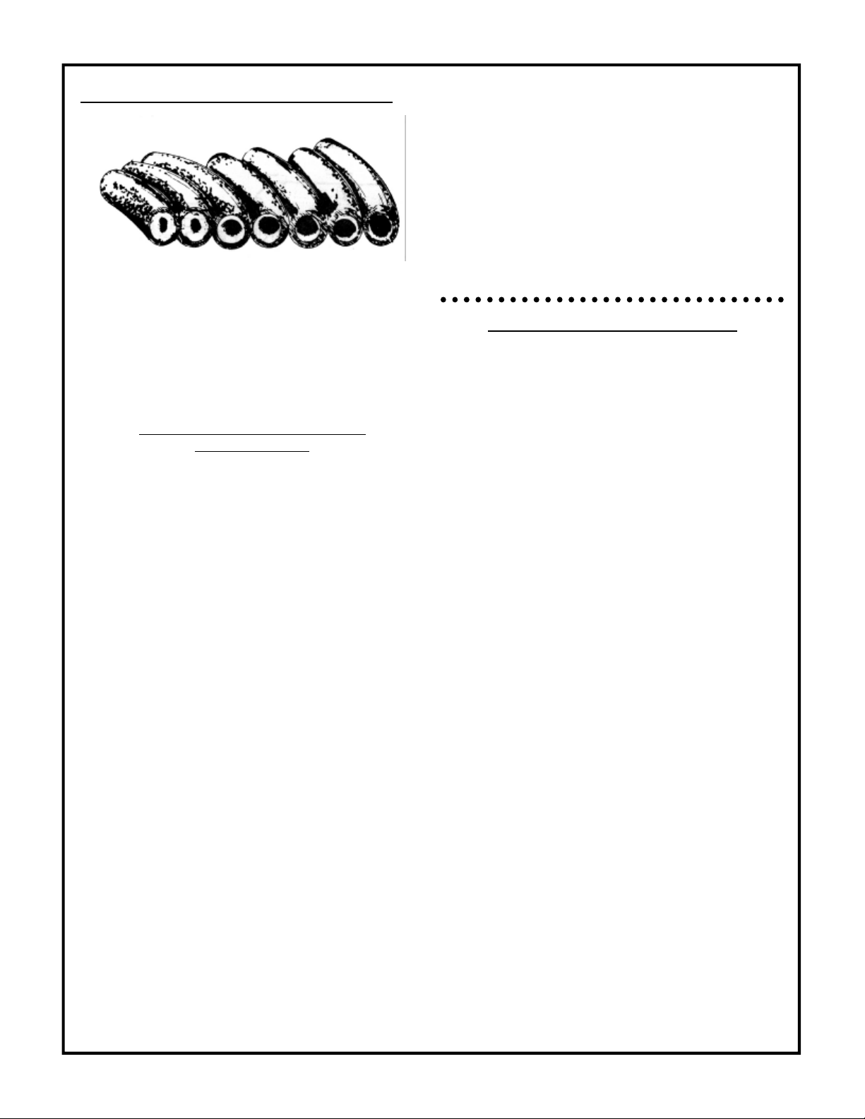
COIL BACK PRESSURE CHECK
Above is a cross section view showing the
progressive liming of coils.
A regular maintenance schedule for descaling your
heating coil is essential to insure its longevity.
The frequency of descaling depends upon the
amount of use and the condition of the water.
COIL BACK PRESSURE CHECK
INSTRUCTIONS
1. Check the condition of your water pump
unloader valve. Remove the hose and gun
assembly from the coil outlet.
2. Remove any flow restrictions, such as guns
and hoses, from the coil outlet.
3. Install a pressure gauge between the water
pump and coil inlet.
DISCHARGE VOLUME BACK PRESSURE
GPM REQUIRING
DESCALING
2-3 GPM 50 PSI
3-4 GPM 75 PSI
4-5 GPM 100 PSI
6 GPM 150 PSI
8-10 GPM 175 PSI
USE A 1000 PSI PRESSURE GAUGE
3. Turn on the water supply. Check the float
valve (if so equipped) to assure float tank is
full and the float valve shuts off securely.
4. Check the position of the ball valve (if so
equipped) on the outlet line of the float tank
assuring it is in the open position.
5. Turn on the pump switch. If the coil back
pressure reading is above that found in the
GENERAL section of the MODEL
SPECIFICATIONS then your machine needs
to be descaled.
A separate descaling pump is recommended so
scale and other chemicals will not come in contact
with your water pump and causes premature wear.
NOTE: Contact your local dealer for descaling of
your unit.
7. Disconnect the water supply.
8. Disconnect the electrical supply.
9. Reinstall the hose and gun assembly.
10. Remove the pressure gauge.
OIL BURNER CONTROLS
A. NORMAL CYCLE:
Turn cam to the burner position. The burner
should start and continue to run normally. (If
the burner starts, establishing flame, but then
locks out on safety, make "Flame Detector
Check" at this time.
B. SAFETY TIMING:
1. Let the burner run 5 minutes. Then remove one
of Flame Detector leads from "F" terminals.
After a time period corresponding to the safety,
stopping the burner.
2. Turn the cam switch to burner position.
3. Replace Flame Detector Lead removed step 1.
4. Wait 3 minutes. Then operate the manual reset
button on the front of control.
C. HIGH LIMIT AND THERMOSTAT CHECK:
1. Turn the cam switch to burner position.
2. Lower the setting of the high limit control to its
lowest setting. This setting should stop the
burner, unless the steam generator
temperature is below the minimum setting of
the high limit.
3. Return the high limit to it's proper setting.
Burner should restart.
4. With the burner running, turn thermostat to
it's lowest setting. This should stop the burner,
unless actual room temperature is below the
lowest setting of the thermostat. (Note: On
systems supplying domestic hot water, burner
will continue to run if low limit is not satisfied.)
5. Return thermostat to it's proper setting.
D. FLAME DETECTOR CHECK: (This test is not
required if control performs as described in
test A.)
08-08-03 Z08-11213G
ECN-02981 10
If the burner starts but the control locks out
(stopping the burner), check the flame detector
as follows:
1. Connect one end of the wire jumper to one of
the "F' terminals.
2. Turn the cam switch to burner position. As
soon as a flame has been established connect
other end of the wire jumper to the other "F"
terminal. WARNING: The control provides no
safety protection with the jumper installed. DO
NOT leave the burner in this condition except
for making this check. If the control still locks
out with the jumper installed, the control
should be replaced. If the control does not lock
out, however, check the operation of the flame
detector.
4. If safety lockout problem is of an intermittent
nature (only lockouts occasionally), the
following additional check may be made to
insure that the flame detector locations is not
a marginal one:
(a) Disconnect flame detector leads from "F"
terminals.
(B) Attach a jumper wire to one "F" terminal. Start
burner. Then immediately connect jumper wire
to the other "F" terminal. Burner should
continue to run.
(c) With burner running, attach flame detector
leads to an accurate ohmmeter. Reading of
ohm meter should also be acceptable,
Generally, though, the lower the reading, the
better the application, and less likely the
chance of a variation in the burner flame
causing a safety lock-out)
(d) If resistance of flame detector is over 1000
ohms, it may not be able to see the burner
flame properly . Check alignment of the flame
detectorthrough thehole inthe staticdisc. Clean
thishole if it is blocked by foreign matter. Check
for broken "F" wires.
(e) If flame detector alignment is a good but
resistance is still high, readjustment may be
necessary.
(f) WARNING: Be sure to remove wire jumper
after this flame detector check.
CHECKOUT PROCEDURE: Before leaving
installation, a complete operating cycle should
be observed to see that all components are
functioning properly. Limit switch function
should be tested to be sure the machine shuts
down when the limit contacts open.
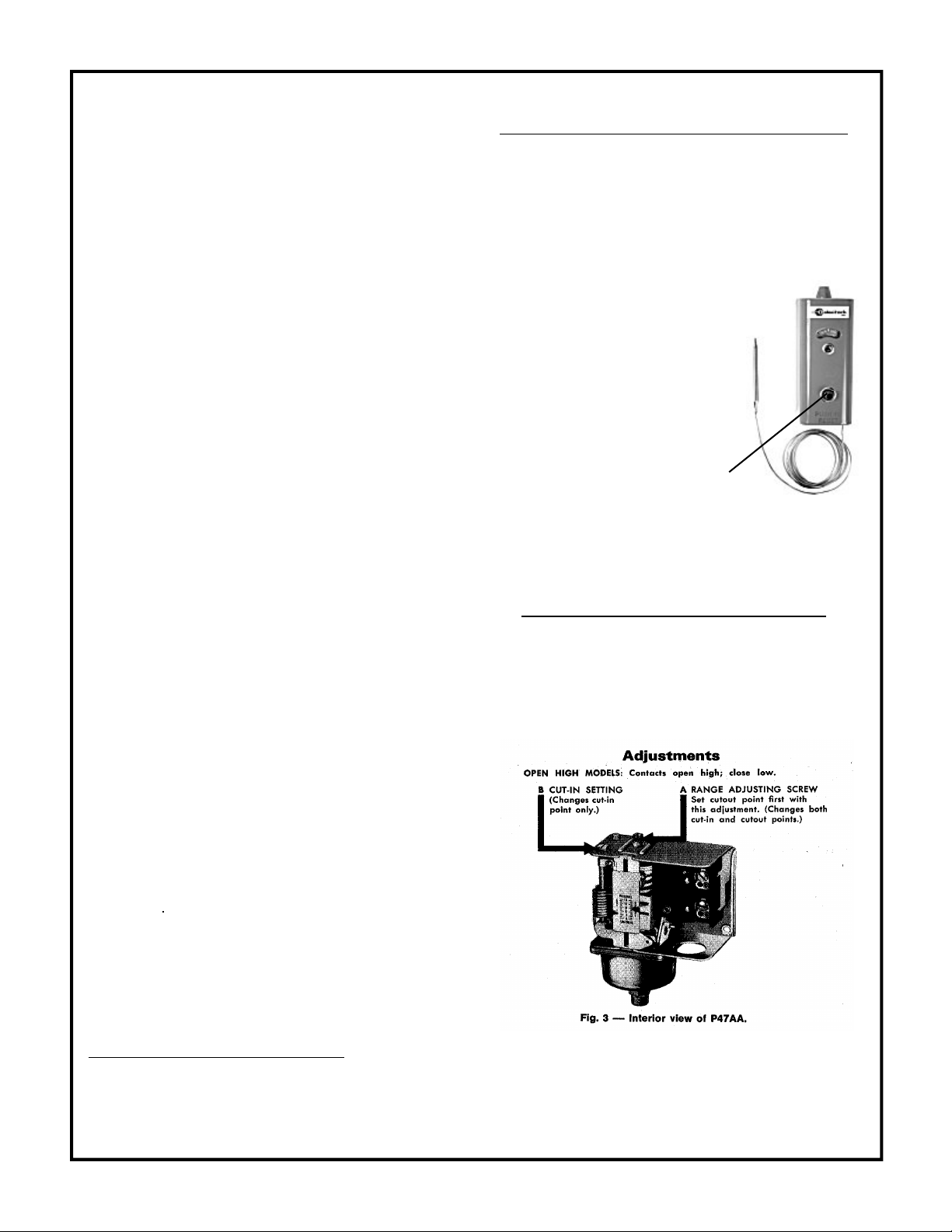
HI LIMIT TEMPERATURE CONTROL
This control has been specifically designed to stop
heating equipment to prevent a dangerous
condition due to excessive temperatures.
A 240V neon pilot light (suitable for 120 to 240
VAC circuits) is included. It can be wired as
shown below to illuminate if the high limit trips
Switch Action:
It is the non-cycling manual reset
type of control which means
that if it's contacts open due
to the temperature exceeding
it's dial setting, the contacts
open, thereby stopping the heat
input to the machine.
MANUAL RESET BUTTON
Non-Cycling Manual Reset:
After this control has stopped the heat input to
the machine, it cannot be started unless some
authorized person pushes the reset button.
STEAM PRESSURE CONTROLS:
OPEN LOW MODELS: Contacts close high:
open low.
On open low models, range adjusting screw "A"
raises and lowers cut-in point (this also raises
or lowers cutout point by a like amount). Sat
cut-in point first with adjusting screw "B"
changes cutout point only. If control is
equipped with a lockout, contacts must be
reset by hand after opening.
08-08-03 Z08-11213H
ECN-02981 11

MOTOR DRIVEN STEAM
GENERATOR DAILY
EACH
HR
FIRST
8 HRS
AFTER
FIRST
50
HRS
EVERY
50
HRS
EVERY
100
HRS
EVERY
500
HRS
YEARLY
OIL BATH WATER PUMP:
Oil Level – check and add as needed per
PUMP SERVICE insert.
Oil Change – drain and refill per PUMP
SERVICE insert. CAUTION: Used oil must
be disposed into an environment safe
container and brought to an oil recycling
center.
Oil Contamination –Milky color indicates
water
HOSES:
Blistering, Loose Covering
Abrasion of cover exposing
reinforcement.
Cuts exposing reinforcement
BELTS:
Cracks or fraying
Belt Tension - For correct belt tension,
see MACHINE MAINTENANCE insert.
FILTER – WATER:
Check water inlet hose screen for debris
Check float tank screen for debris
LEAKS:
Check for water and build up of scale at
pipe connections.
FUEL:
Adequate fuel supply.
FILTER—FUEL:
If contaminants are present see FUEL
FILTER insert.
Remove and Replace fuel filter per FUEL
FILTER insert.
SCREEN—FUEL:
Check fuel pump screen for debris see OIL
BURNER MAINTENANCE insert.
BURNER NOZZLE:
Replace Nozzle as specified in BURNER
section of MODEL SPECIFICATIONS or
BURNER ASSEMBLY insert.
GUARDS AND SHIELDS:
Check that all guards and shields are in place
and secure.
MACHINE MAINTENANCE SCHEDULE
12 08-08-03 Z08-11213J
ECN-02981
OIL BURNER MAINTENANCE
OIL FIRED CLEANERS
08-05-03 Z08-00062
ECN-02981 Supersedes 06-05-01 Z08-00062
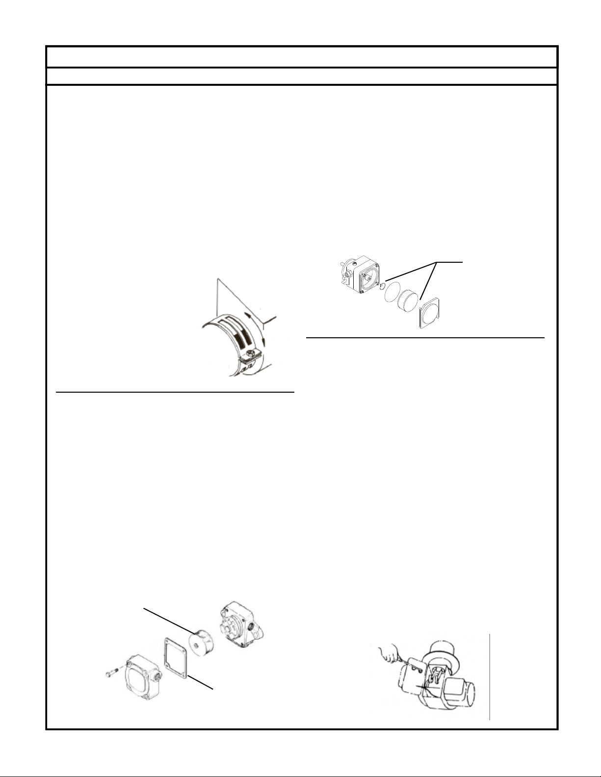
AIR BAND ADJUSTMENT
NOTE: The air band adjustment on this burner
has been preset at the factory (elevation
approximately 1400 feet). On equipment installed
where elevation is substantially different, the air
band(s) must be readjusted.
1. Loosen the cap screw retaining the air bands.
2. Move the air bands as indicated below with
the machine in operation.
NOTE: The air band should be set so the
exhaust gives the smoke spot specified in the
GENERAL section of the MACHINE
SPECIFICATIONS on a Shell-Bacharach scale.
If a smoke tester is not
available, a smoky
exhaust, oily odor, or
sweet smell indicates
insufficient air while eye-
burning fumes indicate
too much air.
3. Tighten the cap screw
retaining the air bands.
FUEL PUMP FILTER
SUNDSTRAND PUMP
1. Shut off fuel supply.
2. Loosen the 4 screws holding the cover to the
fuel pump housing.
3. Take cover and cover gasket off and pull
strainer off of pump housing.
4. Clean out any dirt remaining in the bottom of
strainer cover. If there is evidence of rust
inside of the unit, be sure to remove water in
supply tank and fuel filter.
5. Turn on fuel supply. Failure to do so will result
in fuel pump damage.
DANFOSS PUMP
1. Shut off fuel supply.
2. Loosen the 2 screws with 7/64 allen wrench
one turn.
3. Turn cover counter clockwise and pull strainer
and cover off of pump housing.
4. Clean out any dirt remaining in the bottom of
strainer cover. If there is evidence of rust
inside of the unit, be sure to remove water in
supply tank and fuel filter.
5. Reinstall reverse of removal.
6. Turn on fuel supply.
TRANSFORMER TEST
1. Remove burner junction box cover.
2. Turn on burner and make sure ignition
transformer is receiving rated voltage.
3. Turn off burner.
4. Loosen screw and swing transformer away from
burner gun assembly.
5. Turn on burner.
6. Short the high voltage terminals.
CAUTION: Use screwdriver with a well
insulated handle to avoid shock.
7. Open gap by drawing screwdriver away from
one electrode while touching the other.
8. The spark should jump between 5/8 inches
and 3/4 inches, if it doesn’t jump, replace
the transformer.
9. Turn burner off.
10.Partially close transformer. Check if buss bars
align and contact transformer electrodes. If
buss bars do not contact, see Buss Bar
Alignment.
11.Close transformer, reposition retainer clip and
tighten screw.
PART NUMBER
V00-99004
PART NUMBER
V00-14283-2
PART NUMBER
V00-14283-5

OIL BURNER MAINTENANCE
OIL FIRED CLEANERS
07-11-03 Z08-00062A
BUSS BAR ALIGNMENT
1.With burner off, loosen screw and swing the
transformer away from burner gun assembly.
2. Inspect the buss bars and transformer
electrodes for pitting or corrosion.
3. Partially close the transformer. Check if the
buss bars contact and are in alignment with
transformer electrodes.
4. Proper adjustment is obtained by gently
bending the buss bars until they spring
against, parallel, and are in full contact with
the transformer electrodes.
5. With buss bars aligned, carefully close and
fasten the transformer.
BURNER GUN REMOVAL
& INSTALLATION
1. Disconnect the fuel line from the burner gun
assembly oil line fitting. Loosen the other end
of the line and swing line out of the way.
2. Remove the retaining nut.
3. Loosen screw and swing transformer away from
burner gun assembly.
4. Carefully remove the burner gun assembly.
A. Check and replace electrode insulators if
cracked.
B. Clean burnt buss bars.
C. Clean carbon off electrodes.
D. Clean carbon off oil nozzle. (Use caution
not to scratch face of nozzle or orifice.)
E. Check for a loose oil nozzle. NOTE:
Check with dealer and/or replace nozzle
with proper nozzle.
5. Gently replace burner gun assembly in air
tube. CAUTION: Do not force. Forcing will
cause electrode misalignment
6. Reinstall the retaining nut.
Reinstall the oil line making sure both ends
are tight.
7. Partially close transformer. Check if buss bars
align and contact the transformer electrodes.
If buss bars do not contact, see Buss Bar
Alignment.
8. Close transformer, reposition retainer and
tighten screw.
ACCESSORIES
Z01-00095 – Fuel Nozzle Changing Wrench
Z01-00092 – Fuel Pump Wrench (Sundstrand)
Z01-00093 – Solenoid Wrench (ASCO)
ELECTRODE ASSEMBLY ADJUSTMENT
1.Loosen screws holding electrode assemblies.
2. Raise electrode tips 5/32 inches above
surface plane or end of oil nozzle.
3. Place each electrode tip 5/16 inches from
center of spray nozzle hole, maintaining
previous measurement.
4. Spread electrode tips to 1/8-inch gap
maintaining previous measurements.
5. When the proper measurements are obtained,
gently tighten screws that hold electrode
assembly in place. CAUTION: Do not over
tighten, as this will cause the electrode
insulator to fail.
ECN-02981 Supersedes 06-05-01 Z08-00062A 14

TROUBLE POSSIBLE CAUSE REMEDY
1. Machine will not
rise to operating
pressure.
A. Low fuel pressure.
B. Water in fuel piping.
C. Fuel filter clogged.
D. Poor combustion.
E. Improper fuel supply.
F. Temperature control
inoperative.
A. See BURNER on MODEL
SPECIFICATIONS for specified pressure.
B. Drain fuel tank and remove and replace
filter per FUEL FILTER INSERT.
C. Remove and replace fuel filter element per
FUEL FILTER INSERT.
D. See "Poor combustion".in OIL BURNER
TROUBLESHOOTING.
E. Use fuel specified in BURNER section of
the MODEL SPECIFICATIONS.
F. See HI-LIMIT TEMPERATURE CONTROL
in BURNER CONTROL SECTION.
2. Machine overheats. A. Insufficient water.
B. Temperature control
inoperative.
C. Improper fuel supply.
A. See Low Operating Pressure on MACHINE
TROUBLESHOOTING.
B. See HI-LIMIT TEMPERATURE CONTROL
in BURNER CONTROL SECTION.
C. Use fuel specified in BURNER section of
the MODEL SPECIFICATIONS.
3. Low operating
pressure.
A. Insufficient water supply.
B. Incoming water hose too
small.
C. Water supply hose too long.
D. Belt slippage.
E. Worn Belt.
F. Dirty or worn check valves in
water pump.
H. Water supply hose kinked.
I. Inlet filter screen clogged.
J. Motor runs slow.
K. Air leak in inlet plumbing.
L. Defective water pump.
M. Leaking discharge plumbing.
N. Restricted coil.
A. The water supply must meet or exceed the
maximum discharge volume specified in
the PERFORMANCE section, and
minimum water inlet pressure specified
in the GENERAL section of the MODEL
SPECIFCATIONS section.
B. Use larger water supply hose.
C. Use shorter water supply hose.
D. Tighten belt per instructions in
MACHINE MAINTENANCE insert.
E. Replace belt per CLEANER EXPLODED
VIEW.
F. See PUMP TROUBLESHOOTING.
H. Straighten hose.
I. Clean water filter screen or hose inlet
screen.
J. See "Pump motor starts slow or overheats
and stops" above.
K. Tighten all fittings.
L. See PUMP TROUBLESHOOTING.
M. If a water leak is found, DO NOT
OPERATE THE MACHINE. Disconnect
the power and repair plumbing.
N. See COIL BACK PRESSURE CHECK in
MACHINE MAINTENANCE.
4. Machine fumes
(exhaust burns eyes)
A. Too much combustion air.
B. Improper fuel pressure.
A. See BURNER TROUBLESHOOTING
INSERT.
B. See FUEL in MODEL SPECIFICATIONS
for specified pressure.
ELECTRIC MOTOR DRIVEN OIL FIRED CLEANERS
STEAM GENERATOR TROUBLESHOOTING
ECN -02981 08-21-03 Z08-11215
15

TROUBLE POSSIBLE CAUSE REMEDY
4. Excessive,
unusual noise.
A. Defective Pump.
B. Defective motor.
C. Pulleys rubbing.
D. Misalignment of pump & motor
A. See PUMP TROUBLESHOOTING.
B.Call service technician or take engine to
Repair/Warranty station.
C. Adjust shields or pulley(s).
D. Realign pump and engine.
5. Belts slipping. A. Belts too loose.
B. Excessive Back Pressure.
C. Defective Water Pump.
A. Tighten belt per instructions on
MACHINE MAINTENANCE.
B. See "Excessive Back Pressure" below.
C. See PUMP SERVICE.
6. Excessive Back
Pressure
A. Water pump turning too fast.
B. Coil built up with lime.
C. Relief valve defective.
A. See MODEL SPECIFICATIONS.
B. Delime coil.
C. Remove and replace.
7. Excessive
vibration.
A. Defective Belt.
B. Defective Pump.
C. Defective accumulator
A. Remove and replace using belt specified
in CLEANER EXPLODED VIEW or the
GENERAL section of MODEL
SPECIFICATIONS.
B. See PUMP TROUBLESHOOTING.
C. Recharge/Replace.
8. Pump motor
will not start
(motor does not
hum)
A. No Power.
B. Defective motor starter or
ON/OFF switch.
C. Defective motor.
A. Use a different outlet,check fuses in main
disconnect switch. Replace fuse if blown.
B. Call service technician.
C. Call service technician, or take motor to
Repair/Warranty station.
9. Pump motor
will not start
(motor hums)
A. Pump frozen.
B. Defective motor.
C. Defective water pump.
D. Excessive back pressure
A. Machine must be thoroughly warmed to
above freezing.
B. Call service technician or take motor to
Repair/Warranty station.
C. See PUMP SERVICE.
D. See "Excessive Back Pressure" above.
10. Pump motor
starts slow or
overheats and
stops.
A. Low voltage
B. Excessive back pressure
C. Defective motor
A. See "Low voltage".below.
B. See "Excessive Back Pressure".above.
C. Call service technician, or take motor to
Repair/Warranty station.
11. Pump motor
stops and will
not start.
A. Motor starter "kicked out" (if so
equipped) or thermal overload
tripped.
B. Excessive back pressure.
C. Defective motor.
A. Turn motor starter off to reset, then turn
on, or push thermal overload reset button
on motor.
B. See "Excessive Back Pressure". above
C. Call service technician, or take motor to
Repair/Warranty station.
12. Low voltage A. Incoming voltage incorrect.
B. Not large enough extension cord.
C. Too long extension cord
A. Have a qualified technician check the
motor terminal voltage. Correct voltage is
in MODEL SPECIFICATIONS.
B. Use an extension cord with amperes or
watts rating as high or higher than that of
the MODEL SPECIFICATIONS.
C. Shorten extension cord.
13. Machine
shocks
operator
A. Machine improperly grounded.
B. Outlet not grounded
A. STOP! Operating machine. Call service
technician.
B. Have properly wired outlet installed.
08-21-03 Z08-11215AECN -02981
ELECTRIC MOTOR DRIVEN OIL FIRED CLEANERS
STEAM GENERATOR TROUBLESHOOTING (CONT.)
16

PUMP TROUBLESHOOTING
08-27-03 Z08-00195
ECN-02981 Supersedes 06-00 Z08-00195
TROUBLE POSSIBLE CAUSE REMEDY
1. Oil leaking in the
area of water pump
crankshaft.
A. Worn crankshaft seal.
B. Bad bearing.
C. Grooved shaft.
D. Failure of retainer o-ring
A. Remove and replace.
B. Remove and replace.
C. Remove and replace.
D. Remove and replace.
2. Excessive play on
crankshaft.
A. Defective bearings.
B. Excess shims.
A. See "Worn bearing".
B. Set up crankshaft.
3. Loud knocking in
pump.
A. Loose conecting rod screws.
B. Worn connecting rod.
C. Worn bearings.
D. Loose plunger bushing screw.
A. Tighten connecting rod screws per
PUMP SPECIFICATIONS.
B. Replace connecting rod per PUMP
MAINTENANCE.
C. Replace bearings per PUMP
MAINTENANCE.
D. Tighten plunger screw per PUMP
SPECIFICATOINS.
4. Oil leaking at the
rear portion of the
pump.
A. Damaged or improperly
installed oil gauge window
gasket.
B. Damaged or improperly
installed rear cover.
C. Oil gauge loosed.
D. Rear cover screws loose.
E. Pump overfilled with oil,
displaced through crankcase
breather hole in oil
cap/dipstick.
A. Replace gasket or o-ring.
B. Replace gasket or o-ring.
C. Tighten oil gauge.
D. Tighten rear screws. to torque
values in PUMP SPECIFCATIONS. S
E. Drain oil: refill to recommended oil
level as stated in OIL LEVEL in PUMP
MAINTENANCE.
5. Water in crankcase A. May be caused by humid air
condensing into water inside
the crankcase.
B. Worn or damaged plunger
screw o-ring.
A. Maintain or step up lubrication
schedule.
B. Remove and replace. See PLUNGER
SERVICE in PUMP MAINTENANCE.
6. Worn bearing A. Excessive belt tension.
B. Oil contamination.
A. See BELT TENSION in MACHINE
MAINTENANCE.
B. Check oil type and change intervals
per PUMP SPECIFICATIONS.
7. Short bearing life A. Excessive belt tension.
B. Misalignment between pump
and motor.
C. Oil has not been changed on
regular basis.
A. See BELT TENSION in MACHINE
MAINTENANCE.
B. Re-align pump and motor.
C. Check oil type and change intervals
per PUMP SPECIFICATIONS.
8. Short seal life A. Damaged plunger bushing.
B. Worn connecting rod.
C. Excess pressure beyond the
pump's maximum rating.
D. High water temperature.
A. Replace punger bushing.
B. Peplace connecting rod.
C. Match pressure stated in PUMP
SPECIFICATIONS.
D. Lower water tempersture stated in
PUMP SPECIFCATIONS.
17

PUMP TROUBLESHOOTING
08-27-03 Z08-00195A
ECN-02981
TROUBLE POSSIBLE CAUSE REMEDY
9. Dirty or worn check
valves.
A. Normal wear.
B. Debris
A. Remove and replace.
B. Check for lack of water inlet screens.
10. Presence of metal
particles during oil
change.
A. Failure of internal component.
B. New pump.
A. Remove and disassemble to find
probable cause.
B. New pumps have machine fillings and
debris and should be drained and
refilled per PUMP SPECIFICATIONS.
11. Water leakage from
under head.
A. Worn packing.
B. Cracked/scored plunger.
C. Failure of plunger retainer
o-ring.
A. Install new packing.
B. Remove and replace plunger.
C. Remove and replace plunger retainer
o-ring.
12. Loud knocking
noise
in pump
A. Pulley loose on crankshaft.
B. Defective bearing.
C. Worn connecting rod.
D. Worn crankshaft.
E. Worn crosshead.
A. Check key and tighten set screw.
B. Remove and replace bearing.
C. Remove and replace connecting rod.
D. Remove and replace crankshaft.
E. Remove and replace crosshead.
13. Frequent or
premature failure of
the packing
A. Scored, damaged, or worn
plunger.
B. Overpressure to inlet manifold.
C. Abrasive material in the fluid
being pumped.
D. Excessive pressure and or
temperature of fluid being
pumped.
E. Over pressure of pumps.
F. Running pump dry.
A. Remove and replace plungers.
B. Reduce inlet pressure.
C. Install proper filtration on pump inlet
pumping.
D. Check pressures and fluid inlet
temperature; be sure they are within
specified range.
E. Reduce pressure.
F. Do not run pump without water.
14. Low Pressure A. Dirty or worn check valves.
B. Worn packing.
C. Belt slipping.
D. Improperly sized spray tip or
nozzle.
E. Inlet filter screen is clogged.
F. Pitted valves.
A. Clean/Replace check valves.
B. Remove and replace packing.
C. See BELT TENSION in MACHINE
MAINTENANCE.
D. See MACHINE SPECIFICATIONS for
specified spray tip or nozzle.
E. Clean inlet filter screen.
F. See VALVE SERVICE in PUMP
MAINTENANCE.
15. Erratic pressure:
pump runs rough
A. Dirty or worn check valves.
B. Foreign particles in valve
assemblies.
C. High inlet water temperature
A. Clean/Replace check valves.
A. Clean/Replace check valves.
C. See temperature in PUMP
SPECIFICATIONS.
16. Excessive vibration A. Dirty or worn check valves A. See "Dirty or worn check valves"
17. Scored plungers A. Abrasive material in fluid being
pumped.
A. Install proper filtration on pump inlet
plumbing
18. Pitted plungers A. Cavitation A. Decrease inlet water temperature
and/or increase inlet water pressure.
19. Cavitation A. High inlet fluid
temperatureLow inlet pressure.
A. Lower inlet fluid temperature.Raise
inlet fluid pressure.
18

OIL FIRED BURNER TROUBLESHOOTING
07-15-03 Z08-00191
ECN-02981 Supersedes 08-00 Z08-00191
TROUBLE POSSIBLE CAUSE REMEDY
1. Burner will not
ignite.
A. Electrodes out of alignment.
B. Electrode insulator failure.
C. Water flow switch not closing.
D. Vacuum switch not closing.
E. Temperature control switch not
closing.
F. Fuel solenoid valve not opening.
G. Weak transformer.
H. Faulty cad cell (if equipped).
I. Faulty primary control (if
equipped).
J. Burner motor thermal protector
locked out.
K. Wiring.
L. Burner switch.
M. Pump pressure.
N. Venting.
0. Sooting.
P. No fuel
A. See "ADJUSTING ELECTRODE
ASSEMBLY" in BURNER
MAINTENANCE SECTION.
B. Remove and replace if there are
breaks, cracks, or spark trails.
C. Adjust, repair, or replace switch.
D. Adjust, repair or replace switch.
E. Adjust or replace the TEMPERATURE
CONTROL.
F. Clean, repair, or replace solenoid.
G. Clean and check transformer
terminals. Check transformer for
spark per "TRANSFORMER TEST" in
BURNER MAINTENANCE SECTION.
H. Clean and test cad cell, replace if
required.
I. Replace primary control.
J. See "Burner motor thermal protector
locked out.
K. All wire contacts are to be clean and
tight. Wire should not be cracked or
frayed.
L. Test switch operation. Remove and
replace as necessary.
M. See "Low fuel pressure".
N. A downdraft will cause delayed
ignition. Soot deposits on the coil and
burner can interrupt air flow, and
cause shorting of the electrodes. Clean
as required.
O. Soot deposits on the coil and burner
can interrupt air flow, and cause
shorting of the electrodes. Clean as
required.
P. See "No fuel."
2. No fuel A.Clogged fuel filter.
B. Fuel leak.
C. Kinked or collapsed fuel line.
D. Low fuel pressure.
E. Faulty burner oil pump.
F. Air leak in intake lines.
G. Clogged burner nozzle
A. Remove and replace filter per FUEL
FILTER SECTION.
B. Repair as necessary.
C. Remove and replace fuel line.
D. See "Low fuel pressure".
E. Adjust pressure or replace.
F. Tighten all fittings.
G. Remove and replace (Do not clean).
3. Low fuel pressure A. Clogged fuel filter.
B. Clogged fuel pump filter
screen.
C. Fuel oil too viscous.
D. Air leaks in intake lines.
E. Kinked or collapsed fuel line.
F. Burner shaft coupling slipping.
G. Fuel Nozzle worn.
H. Faulty oil pump
A. Remove and replace filter per FUEL
FILTER page.
B. Remove pump cover and clean strainer
using a brush and clean fuel oil, diesel
oil or kerosene.
C. Operate a lighter oil or in warmer area.
D. Tighten all fittings.
E. Remove and replace.
F. Remove and replace.
G. Remove and replace with specified
nozzle on BURNER ASSEMBLY.
H. Remove and replace.
19

OIL BURNER TROUBLESHOOTING
07-15-03 Z08-00192
ECN-02981 Supersedes 09-00 Z08-00192
TROUBLE POSSIBLE CAUSE REMEDY
4. Pulsating pressure A. Partially clogged fuel pump
strainer or filter.
B. Air leaking around fuel pump
cover.
A. Remove and replace strainer per FUEL
PUMP FILTER in OIL BURNER
MAINTNANCE Section.
B. Check fuel pump cover screws for
tightness and damaged gasket.
5. Unit smokes A. Improper fuel.
B. Air to burner insufficient.
C. Fuel nozzle interior loose.
D. Water in fuel.
E. Gun out of alignment.
A. Refuel with FUEL specified on
MACHINE SPECIFICATIONS.
B. See AIR BAND ADJUSTMENT in OIL
BURNER MAINTENANCE section.
C. Replace nozzle.
D. Inspect fuel filter for water presence.
E. Bend oil pipe to center burner nozzle.
6. Burner motor
thermal protector
kicked out.
A. Low voltage.
B. Fuel too viscous.
C. Fuel pump defective.
D. Motor defective.
A. Voltage must match those specified in
the BURNER section of MACHINE
SPECIFICATIONS section.
B. Operate in warmer conditions or with
fuel adapted to cold weather
conditions.
C. Check that fuel pump turns freely.
D. Call service technician or take motor to
repair/warranty station.
7. Delayed ignition
(rumbling, noisy
starts)
A. Dirty or damaged electrodes.
B. Air adjustment open too far.
C. Poor fuel spray pattern.
D. Incorrect electrode setting.
E. Weak transformer
A. Clean or replace.
B. Readjust per AIR BAND ADJUSTMENT
in OIL BURNER MAINTENANCE
section.
C. Remove and replace with fuel nozzle
specified in BURNER ASSEMBLY.
D. Readjust per ADJUSTING
ELECTRODE ASSEMBLY in OIL
BURNER MAINTENANCE section.
E. See TRANSFORMER CHECK on OIL
BURNER MAINTENANCE section
8. Burner does not
electrically come on
A. Burner motor reset button
tripped.
B. High limit temp control reset
tripped if so equipped.
A. Reset if necessary.
CAUTION: Do not keep hitting the "reset
button" if you have oil pressure you
are just filling the burner combustion
chamber with oil and if ignited will
cause an explosion.
B. Reset if necessary.
20
Table of contents
Popular Portable Generator manuals by other brands


SIGLENT TECHNOLOGIES
SIGLENT TECHNOLOGIES UM0202X-E02D user manual

Powermate
Powermate PM0401857 user manual

BRICK
BRICK BGI3000S Original Notice

Mecafer
Mecafer MF4500E manual

Mitsubishi Heavy Industries
Mitsubishi Heavy Industries MGE1801 owner's manual

Clarke
Clarke IG2000D Operation & maintenance instructions

Stager
Stager YDE12000E user manual

Rohde & Schwarz
Rohde & Schwarz SMW-K141 user manual

PISCO
PISCO VNE04 user manual

HISPANUS
HISPANUS LIGEROS-3500 manual

Champion Global Power Equipment
Champion Global Power Equipment 500110-N Owner's manual & operating instructions

Tomahawk
Tomahawk TG2000i Operation manual