* Please make inquiry about other details to the following.
OVERSEAS MARKETING TEAM
3884-1
MINAMIMINOWA,
KAMIINA,
NAGANO-PREF
,
399-4588,
JAPAN
TEL:
+81-(0)265-76-7751
F
AX:
+81-(0)265-76-3305
E-mail:
[email protected]Safety Instructions
Nozzle
Lock pin
Fixing screw
Vacuum release solenoid valve
Vacuum port block with sensor unit
Diffuser
O-ring
Circuit diagram
Limit circuit
-0V
(Black)
+24V
(Red)
ANALOG OUT
(Black)
+10.8~30VDC
(Brown)
-0V (Blue)
Main
circuit
How to fit and release Tubing
How to fix Vacuum Generator VN
6.4
12
How to adjust vacuum release flow
Vacuum release air flow adjusting needle
The vacuum release air flow rate can be
increased by turning the needle left.
The vacuum release air flow rate can be
decreased by turning the needle to the right.
The vacuum release air flow rate can be
increased by turning the needle left.
The vacuum release air flow rate can be
decreased by turning the needle to the right.
How to replace the filter elementHow to replace the silencer element
How to install, remove and clean the nozzle and diffuser
How to replace silencer elements for manifold type
Specifications
Ejector characteristics
Solenoid valve specifications
Vacuum release function
Vacuum switch specifications
Voltage
Electric
current
about 20msec
Electric current and voltage waveform at valve excitation
At start-up
(power consumption: 2.2W)
At start-up
(power consumption: 2.2W)
At retention
(power consumption: 0.6W)
Vacuum flow
20
8+10.3×n
(n=No. of manifold)
10
How to replace cartridge fitting
Thank you for purchasing PISCO
product. Please be sure to read this
User's Manual before using this item in
order to make sure the safety. Please
keep this manual handy with care, so that
you can refer to it whenever necessary.
PISCO products catalogues include
Common Safety Instructions for PISCO
products and Vacuum equipment. Please
confirm the Safety Instructions as well
before using this item.
Vacuum GeneratorVN
Vacuum pump system-compatible unitVNP
User's Manual
HIR0070-00
●Warning
[Products Handling]
1. Do not step onto or place objects on the devices. These may cause falling accident, fall of devices, injuries from falling and
malfunctions from device breakage.
2. Do not wash or paint the devices with solvent or water. Solvent use may cause breakage of resin parts and malfunction by
port clogs.
3. Mishandling of compressed air is dangerous. Conduct assembly and maintenance of devices with pneumatic equipment
by persons with enough knowledge and experience.
4. Since this item is not of explosion-proof structure, do not use it with or in surroundings containing flammable or explosive
gases or fluids. Avoid use it where there are constant pressures of 0.1MPa (14.5psi) or above in the vacuum circuit.
[Products maintenance]
1. Carry out maintenance and checks of equipment only after turning power off, shutting air off and making certain that the
residual pressure in the piping has dropped to zero.
2. When installing wiring and piping, be sure to switch off the power and make sure there is no miswiring and mispiping before
applying power and air.
3. In tightening the screw, use the recommended tightening torque. The recommended tightening torque for xing device is
specied on "How to x Vacuum Generator VN". The recommended tightening torque for solenoid valve is 0.15 ~ 0.2N·m.
Improper tightening may cause air leakage, dropout or breakage of the products.
[Products application]
1. For the operation of the valve, make certain that the leakage
current is less than 1mA. Leakage current larger than that may
cause malfunction.
2. Avoid applying excessive vibration or shocks to the devises. It
may damage devises and lead to malfunction of solenoid valve.
3. Long continuous power supply to the valve may raise the
temperature of the coil. Heat may cause burns or affect the
surrounding equipment adversely. Consult PISCO about such
applications.
4. Current limit circuit is adopted for the solenoid valve. It features
the current drop when the coil is energized and retains current.
Therefore, the use in the location having vibration or shock
greater than the specication below must be avoided. It may
cause valve malfunction.
●Caution
[Products Handling]
1. Do not pull or bend lead wires of solenoid valve or vacuum switch excessively. Doing so may result in disconnection of lead
wires or connector components broken.
2. Compressed air contains plenty of drain (Water, oxidized oil, tar and foreign particles etc.). Since drain may cause
performance drop, conduct air dehumidication by the after-cooler and drier, then improve air quality.
3. Never supply rubricated air.
4. Rust and inow of foreign particles in piping cause malfunction and performance drop. Therefore, install a lter (ltration
capacity: max. 5μm) just before the air supply port. On top of it, Prior-to-use and periodic ushing is recommended.
5. Do not use the devises in the atmosphere of corrosive and ammable gas. In addition, do not use the gas as uid admitted.
Since this product is not explosion-proof type, it may cause re and explosion.
6. Do not use the devices in locations where they can be exposed to water drops, oil drops, dust, etc. Since this product is not
drip or dust proof type, they may cause breakage or performance drop.
7. The lead wire of solenoid valve is polarized. Therefore, the solenoid valve is not activated by wrong polarity.
8. If continuous current is supplied to the solenoid for 15 minutes or more, please limit number of such energization to 10 times
per day maximum.
[Products maintenance]
1. When replacing cartridge ttings for air supply (PS, PV) or vacuum (V) port, be sure to remove extraneous matter from the
seal and x the fastening pin rmly in place.
2. The performance of silencer tted ejector unit and lter tted vacuum pump compatible unit may deteriorate due to dust
trapped in the elements. Therefore, we recommend cleaning well or replacing the elements at just the right time.
[Products application]
1. In selecting the piping to the vacuum (V) port, save piping bore and length for enough effective sectional area. Insufcient
effective sectional area may cause performance drop in characteristics such as suction ow and vacuum release airow.
2. In selecting the piping to the supply (PS,PV) port, save piping bore and length for enough effective sectional area.
Insufcient effective sectional area may cause performance drop due to short supply of compressed air and vacuum ow.
3. This product is not equipped with a vacuum lter. Therefore, use PISCO vacuum lter at the same time. If the lter is not
used, dust or other particles are accumulated inside the product and cause vacuum performance drop (ejector unit) and
solenoid valve malfunction such as air leakage. (ejector unit and vacuum pump compatible unit) (Recommended lter: VFU
series and VFJ series)
4. As the series number of manifolds increases, there is limitation on the simultaneous activation-allowable series depending
on the condition of the air supply (supply port size, piping length, regulator processing flow rate and etc.) and/or air
consumption (vacuum characteristics) of ejector and other such problems may possibly be encountered. Consult PISCO
sales ofce on this matter.
5. Although vacuum Generator VN series manifold type is the open to air exhaust by individual unit, the exhaust air from a
vacuum-generating unit may be exhausted to the vacuum port of other non-activating units. If this is a matter, please consult
PISCO sales ofce.
■Common to all VN series
Unit Ejector unit Vacuum pump compatible unit
Fluid admitted Air
Service pressure range 0 ~ 0.55MPa
Service temperature range 5 ~ 50°C (Non condensing)
Service humidity range 35 ~ 85%RH (Non condensing)
Protective structure IEC standard IP40 equiv.
Vibration and shock resistance 50m/s2max. /150m/s2max.
Working vacuum – 0 ~ -100kPa
■Ejector unit
Model Nozzle dia.
(mm)
Pressure supply
(MPa)
Final vacuum
(-kPa)
Suction ow
(l/min[ANR])
Air consumption
(l/min[ANR])
VNE04 0.4 0.35
90.4
2 6
VNH05 0.5 0.5 7 11.5
VNE05 0.35 3 8
VNH06 0.6 0.5 9.5 16
VNE06 0.35 5 12
■Common to all VN series
Unit Ejector unit Vacuum pump compatible unit
Item
Vacuum making solenoid valve Vacuum release solenoid valve
Vacuum supply solenoid
valve
Vacuum release solenoid valve
Operating system Direct operation
Valve construction Elastic seal, poppet valve
Voltage rating DC24V
Allowable voltage range ±10%
Surge limiting circuit Equipped with surge noise filter
Power consumption On start-up: 2.2W, On retention: 0.6W (Equipped with power saving circuit)
Operation indicator Green LED
Service pressure range 0 ~ 0.55MPa 0 ~ 0.55MPa -100 ~ 0kPa 0 ~ 0.55MPa
Valve type Normally closed
Response time (※)Max. 5msec. at vacuum generation (OFF→ON) and vacuum stop (ON→OFF).
Wiring method Connector type (Cable length: 500mm)
Red color lead wire: +24VDC, Black color lead wire: -0V
(※) The response time is the time elapsed, at supply of a supply pressure and the rated supply voltage, before a change in pressure is detected at
the vacuum port. The time required to reach vacuum and the time required to release the vacuum, both measured at the end of the piping (at
the work piece), depend on factors such as the volume (piping length) and vacuum release airow., etc.
■Common to all VN series
Vacuum release air ow 0 ~ 20l/min[ANR] (Air supply pressure is 0.5MPa)
* Variable by vacuum release flow adjusting needle.
■Vacuum pump compatible unit
Vacuum ow 8l/min[ANR] (Air supply pressure is -80kPa)
■Common to all VN series
Item Negative pressure type (-V1) Compound pressure type (-R1)
Wire connection method Connector type Grommet type
Supply voltage DC10.8 ~ 30V (ripples included)
Current consumption 20mA max. (DC24V at no-load)
Pressure detection Proliferated semiconductor pressure sensor, gauge pressure
Service pressure range -100 ~ 0kPa -100 ~ 300kPa
Proof pressure 1,000kPa 600kPa
Storage temperature range -20 ~ 70°C (Atomospheric pressure, hummidity less than 65%RH)
Operating temperature range -10 ~ 60°C (Non condensing)
Operating humidity range 35 ~ 85%RH (Non condensing)
Protective structure IEC standard IP40 equiv.
Analog output
Output voltage 1 ~ 5V
Zero-point voltage
1±0.04V (= at atmospheric) 1±0.1V (= at -100kPa)
Max. rated pressure voltage
4.6±0.04V (= at -90kPa) 5±0.1V (= at 300kPa)
Linearity ±0.5%F.S. max. (at Ta=25°C)
Temperature characteristics
±2%F.S. max. (0 ~ 50°C、Ta=25°C)
Output current
0.495mA max. (Load resistance: 10kΩmax.)
1mA max. (Load resistance: 5kΩmax.)
■Solenoid valve ■Pressure sensor
(1). Tube insertion
Simply insert a tubing into the tube
end of tting of Vacuum Generator
VN(ejector equipped with tube
fitting) and Vacuum unit VNP
(vacuum pump compatible unit
equipped with tube fitting). The
lock-claws automatically fix the
tubing, and elastic sleeve seals the tube surrounding. Please
refer to ''2. Cautions on the tting of tube'' in Common Safety
Instructions for Quick-Fitting Joint of general catalogue.
(2). Tube Release
In case of releasing the tube, push
the release ring. The lock-claws
open and the tube can be released.
Before releasing the tube, make
certain to turn off the air supply.
Use M3 screws to x the unit with the two mounting holes by the recommended tightening torque of 0.3-0.5N.m. Use of a
torque other than the recommended level may cause dropout or breakage of the products. (Please refer to the following
drawing for the dimension of hole pitch).
Turning the airflow adjustment needle clockwise decreases the flow rate of vacuum release air, while turning the needle
counterclockwise increases the ow.
● Warning
1. When removing tubing from the unit, be sure to turn offthe air supply and discharge residual air pressure completely.
2. Install the piping by checking the location of air supply port, vacuum port and exhaust port in the catalogue.
● Caution
1. Do not apply excessive vibration or shock to the unit. Using it in such condition can lead to malfunctions and/or errors.
● Caution
1. Make sure to use an appropriate at-blade screwdriver for adjusting vacuum release airow.
2. This product incorporates an internal spring as the needle rotation lock. Therefore, a locknut is not equipped on the
needle. Do not use a wrench on the hexagonal part. It may cause breakage.
● Caution
1. Do not pull or bend lead wire, connector cable, and sensor cable excessively or avoid excessive repeated motion. Such
use may cause the disconnection of wire/cable or breakage of the product.
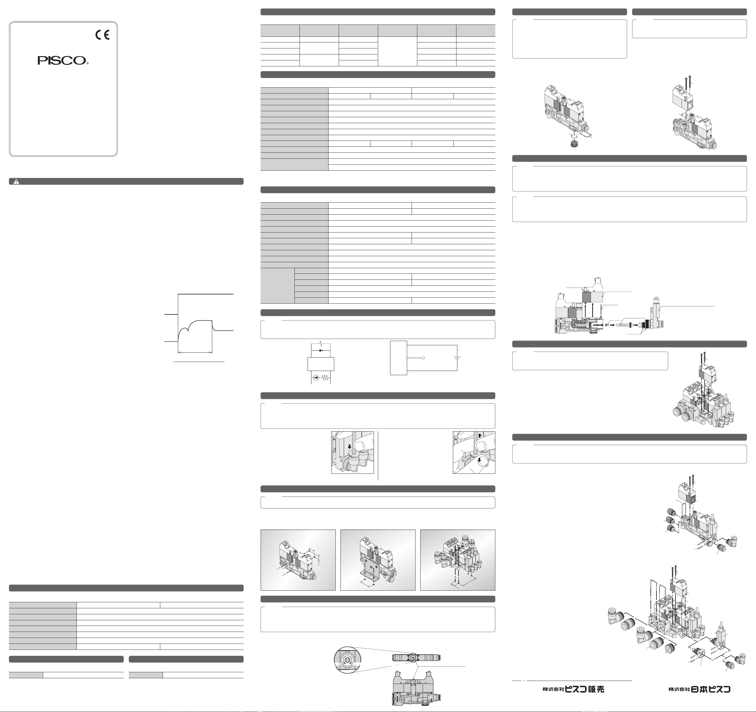
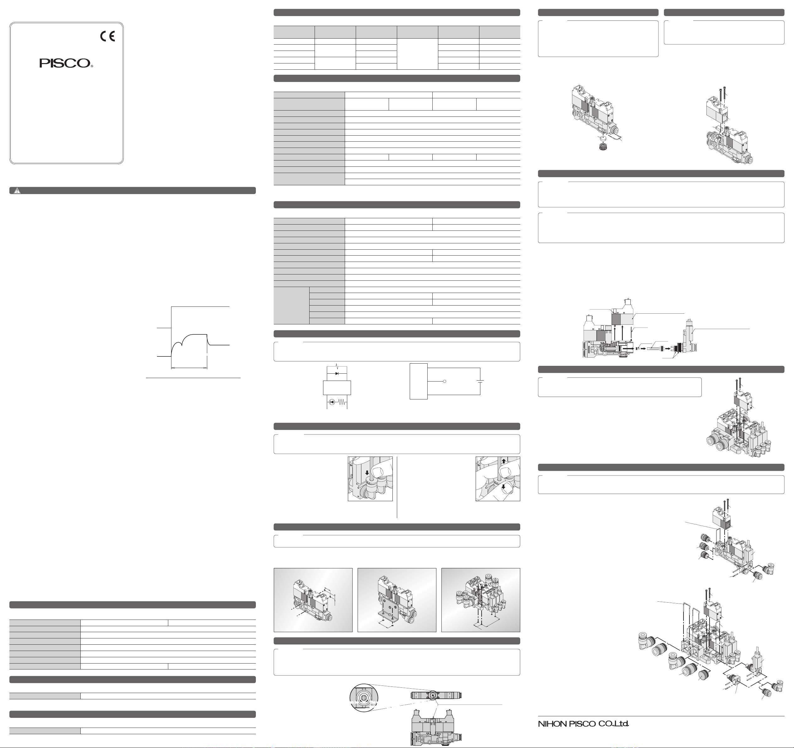
Manifold typeFixing stand alone type using bracketDirect xing of stand alone type
To remove the diffuser, rst remove the vacuum release solenoid valve, locking pin for vacuum port block with or without sensor
unit. Then, pull out the diffuser using needle-nose pliers etc. To prevent the nozzle from jumping out, cover the main body with
a cushioning material (sponge etc.), and supply vacuum making air (*1) and energize vacuum making solenoid valve. After the
nozzle has been blasted out by air, remove the cushioning material and take out the nozzle.
Remove any foreign matter attached to the nozzle, diffuser interior and seal using air blow, through wiping (*2) etc.
Install the nozzle on the diffuser, and insert to the main body, taking care that the nozzle is not detached from the diffuser. Push
in the diffuser by taking care not to damage the tip and install the vacuum port block with or without sensor unit. After inserting
the locking pin to x the vacuum port, tighten the vacuum release solenoid valve by the xing screws with a tightening torque
of 0.15-0.2N.m. For installation of the silencer element, refer to "How to replace the silencer elements".
Replacement of filter elements (Model : VN012B32) of
vacuum pump compatible unit, stand-alone type is conducted
by removing the xing screws of vacuum supply valve by an
appropriate Philips screwdriver. After new lter element has
been put in place, conrm that lter packing for the vacuum
supply solenoid valve is placed in right position, and x the
screws rmly at a tightening torque of 0.15-0.2N.m.
As for the replacement of silencer element (Model
:VN012B33) of ejector system-compatible unit stand-alone
type, pull the locking pin by a flat-blade screwdriver. After
replacing the element, make sure the locking pin is firmly
inserted.
Replacement of silencer elements (Model : VN013B19) of manifold type ejector
unit is conducted by removing the vacuum release valve by an appropriate Philips
screwdriver. After new silencer element has been put in place, confirm that the
rubber gasket for vacuum supply solenoid valve is placed in right position, and x
the screws rmly at a tightening torque of 0.15-0.2N.m.
● Caution
1. After replacing the filter element, be sure to fix the
valve by fixing screws firmly with a tightening torque of
0.15 ~ 0.2N·m.
● Caution
1. After replacing the silencer element, be sure to insert
the lock pin firmly.
2. Be careful of the direction of locking pin. If the locking
pin is inserted in reverse, the pin may drop off due to
vibration.
● Warning
1. When supplying air to the unit, do not direct the nozzle outlet at human body. The nozzle may jump out, causing injury.
2.
By supplying air without having installed the vacuum release valve, the air blows out from the square hole of main unit. In
cases like this, close vacuum release air adjusting needle completely before supplying air.
● Caution
1. After replacing the silencer element, be sure to fix the valve by fixing screws
firmly with a tightening torque of 0.15 ~ 0.2N·m.
● Caution
1. When installing the vacuum port block to the main body, be sure to conrm that no dust, uff, etc. are sticking to the
O-ring.
2. Do not damage the nozzle, diffuser interior, sealing surface, seal parts (O-ring) and interior part of main body. Otherwise,
the unit performance may deteriorate.
Lock pin
Silencer element
Fixing screw
Vacuum supply solenoid valve
Filter element
Fixing screw
Vacuum release
solenoid valve
Silencer element
● Caution
1. When installing cartridge tting, be sure to conrm that no dust, uff, etc. are sticking to the O-ring. Do not damage the
interior part of main body. The damage causes performance drop due to air leakage in vacuum circuit.
<Stand-alone type>
■Vacuum port
Pull out the spring pins (2 pieces) inserted from the side of
vacuum port block with or without sensor unit by the jig like
ø1mm pin and replace the cartridge tting.
■Supply port
Using a suitable Philips screwdriver, remove the vacuum
making solenoid valve or vacuum supply solenoid valve.
Pull out the locking pin of ports (air supply port, air supply
port for vacuum generation and air supply port for vacuum
release) using a flat-blade screwdriver and replace the
cartridge ttings. After checking the rubber gasket for the
solenoid valve is not missing, securely tighten the two xing
screws at a torque of 0.15-0.2N.m.
<Manifold type>
■Vacuum port
Using a suitable Philips screwdriver, remove
the vacuum release solenoid valve. Pull out
the locking pin using a flat-blade screwdriver
and remove the vacuum port block with or
without sensor unit. Pull out the spring pins (2
pieces) inserted from the side of the vacuum
port block by the jig like ø1mm pin and replace
the cartridge ttings. After checking the rubber
gasket for the solenoid valve is not missing,
securely tighten the two fixing screws at a
torque of 0.15-0.2N.m.
■Supply port
Pull out the locking pin of ports using a flat-
blade screwdriver and replace the cartridge
ttings.
* Be careful of the direction of locking pin. If the
locking pin is inserted in reverse, the pin may
drop off due to vibration.
Fixing screw
Vacuum release solenoid valve
Lock pin for vacuum port
Vacuum port
block with
Sensor unit
Vacuum port block
Spring pin
Cartridge
Lock pin for vacuum
making air supply port &
air supply port
Plug
Cartridge
Fixing screw
Vacuum making solenoid valve or
Vacuum supply solenoid valve
Lock pin for vacuum
making air supply port &
air supply port
Cartridge
Spring pin
Plug
Cartridge
Vacuum port block
with or without
sensor unit