Seco SECOCQ7-mITX2.0 User manual

SECOCQ7-mITX2.0
Carrier Board for Qseven®and μQseven® modules, Rel.2.0 compliant, on
mini ITX form factor
SECOCQ7-mITX2.0
User Manual

SECOCQ7-mITX2.0
User Manual - Rev. First Edition: 1.0 - Last Edition: 1.0 - Author: S.B. - Reviewed by G.M.
Copyright © 2013 SECO S.r.l.
SECOCQ7-mITX2.0
Page 2
REVISION HISTORY
Revision
Date
Note
Rif.
1.0
17th April 2013
First release
SB
All rights reserved. All information contained in this manual is proprietary and confidential
material of SECO S.r.l.
Unauthorised use, duplication, modification or disclosure of the information to a third-party by any
means without prior consent of SECO S.r.l. is prohibited.
Every effort is been made to ensure the accuracy of this manual; however, SECO S.r.l. accepts no
responsibility for any inaccuracies, errors or omissions herein. SECO S.r.l. reserves the right to
change precise specifications without prior notice to supply the best product possible.
For further information as regards this module or other SECO products please visit our website at
http://www.seco.com.
Moreover in order to have the proper assistance for any possible issue please contact us using
dedicated web form available at http://www.seco.com/en/contatti.html (registration required).
Our team will be pleased and ready to assist you.
SECO S.r.l - Via Calamandrei 91
52100 Arezzo –ITALY
Ph.: +39 0575 26979 Fax: +39 0575 350210
www.seco.com
www.secoqseven.com

SECOCQ7-mITX2.0
User Manual - Rev. First Edition: 1.0 - Last Edition: 1.0 - Author: S.B. - Reviewed by G.M.
Copyright © 2013 SECO S.r.l.
SECOCQ7-mITX2.0
Page 3
INDEX
CHAPTER 1 INTRODUCTION ...................................................................................................4
1.1 WARRANTY............................................................................................................................................ 5
1.2 INFORMATION AND ASSISTANCE .............................................................................................................. 6
1.3 RMA NUMBER REQUEST......................................................................................................................... 6
1.4 SAFETY ................................................................................................................................................. 7
1.5 ELECTROSTATIC DISCHARGES................................................................................................................ 7
1.6 ROHS COMPLIANCE ............................................................................................................................... 7
CHAPTER 2 OVERVIEW ...........................................................................................................8
2.1 INTRODUCTION....................................................................................................................................... 9
2.2 TECHNICAL SPECIFICATIONS................................................................................................................. 10
2.3 MECHANICAL SPECIFICATIONS .............................................................................................................. 11
2.4 ELECTRICAL SPECIFICATIONS................................................................................................................ 12
2.4.1 RTC Battery................................................................................................................................. 12
CHAPTER 3 CONNECTORS...................................................................................................14
3.1 CONNECTORS PLACEMENT -OVERVIEW ................................................................................................ 15
3.2 CONNECTORS OVERVIEW ..................................................................................................................... 16
3.2.1 Jumper Summary ........................................................................................................................ 16
3.2.2 Connectors Summary.................................................................................................................. 16
3.3 CONNECTORS DESCRIPTION................................................................................................................. 17
3.3.1 Qseven®Connector..................................................................................................................... 17
3.3.2 LVDS / embedded Display Port Connector ................................................................................. 20
3.3.3 Backlight connector ..................................................................................................................... 20
3.3.4 Display ID EEPROM socket ........................................................................................................ 21
3.3.5 DisplayPort / HDMI Connector..................................................................................................... 22
3.3.6 Camera interfaces ....................................................................................................................... 23
3.3.7 Audio Section............................................................................................................................... 26
3.3.8 USB 2.0 + Gigabit Ethernet combo connector ............................................................................ 27
3.3.9 Factory Alternatives USB 2.0 / USB 3.0 Connectors................................................................... 28
3.3.10 PCI Express x16 Expansion Slot................................................................................................. 30
3.3.11 Serial ports................................................................................................................................... 32
3.3.12 SD/MMC Card connector............................................................................................................. 33
3.3.13 S-ATA connector ......................................................................................................................... 33
3.3.14 mSATA Slot ................................................................................................................................. 34
3.3.15 I2C EEPROM socket ................................................................................................................... 34
3.3.16 Feature Connector....................................................................................................................... 35
3.3.17 SPI Pin Header............................................................................................................................ 35
3.3.18 SPI Flash socket.......................................................................................................................... 36
3.3.19 LPC Pin Header........................................................................................................................... 36
3.3.20 FAN Connector............................................................................................................................ 36
3.3.21 Front Header Interface................................................................................................................. 37
3.3.22 MFG Connector ........................................................................................................................... 37

SECOCQ7-mITX2.0
User Manual - Rev. First Edition: 1.0 - Last Edition: 1.0 - Author: S.B. - Reviewed by G.M.
Copyright © 2013 SECO S.r.l.
SECOCQ7-mITX2.0
Page 4
Chapter 1 INTRODUCTION
Warranty
Information and assistance
RMA number request
Safety
Electrostatic Discharges
RoHS compliance
SECOCQ7-mITX2.0
User Manual - Rev. First Edition: 1.0 - Last Edition: 1.0 - Author: S.B. - Reviewed by G.M.
Copyright © 2013 SECO S.r.l.
SECOCQ7-mITX2.0
Page 5
1.1 Warranty
This product is subject to Italian law D. Lgs. 24/2002, acting European Directive 1999/44/CE on
arguments of sale and warranties to consumer.
The warranty for this product lasts 1 year
Under the warranty period the Supplier guarantees the buyer an assistance service for repairing,
replacing or credit of the item, at its own discretion.
Shipping costs regarding non-conforming items or items that need replacement are to be paid by
the customer.
Items cannot be returned unless formerly authorised by the supplier.
The authorisation is released after compiling the specific form available from the web-site
http://www.seco.com (RMA Online). Authorisation number for returning the item must be put both
on the packaging and on the documents brought with the items, which have to be not damaged,
not tampered, with all accessories in their original packaging.
Error analysis form identifying the fault type has to be compiled by the customer and has to be sent
in the packaging of the returned item.
If some of the above mentioned requirements for returning the item are not satisfied, item will be
shipped back and customer will have to pay for shipping costs.
The supplier, after a technical analysis, will verify if all the requirements for warranty service are
met. If warranty cannot be applied, he calculates the minimum cost of this initial analysis on the
item and the repairing costs. Costs for replaced components will be calculated aside.
Warning! All changes or modifications to the equipment not clearly approved by
SECO S.r.l. could impair equipment’s functionality and lead to the
expire of the warranty

SECOCQ7-mITX2.0
User Manual - Rev. First Edition: 1.0 - Last Edition: 1.0 - Author: S.B. - Reviewed by G.M.
Copyright © 2013 SECO S.r.l.
SECOCQ7-mITX2.0
Page 6
1.2 Information and assistance
What do I have to do if the product is faulty?
SECO S.r.l. offers the following services:
SECO website: visit http://www.seco.com to receive the last information on the product. In
most of the cases you can find useful information to resolve your problem.
SECO reseller: the reseller or agent can help you in determining the exact cause of the
problem and search the best solution for it.
SECO Help-Desk: contact SECO Technical Assistance.
A technician is at your disposal to understand the exact origin of the problem and suggest the right
solution. E-mail: technical.service@seco.com
Fax (+39) 0575 340434
Repairing centre: it is possible to send the faulty product to SECO Repairing Centre. In this
case, follow this procedure:
Returned items have to be provided with RMA Number. Items sent without RMA
number will be not accepted.
Returned items have to be packed in the appropriate manner. SECO is not responsible
for damages caused by accidental drop, improper usage, or customer neglects.
Note: We ask to prepare the following information before asking for technical assistance:
- Name and serial number of the product;
- Description of Customer’s peripheral connections;
- Description of Customer’s software (operative system, version, application software, etc.);
- A complete description of the problem;
- The exact words of every kind of error message received
1.3 RMA number request
To request a RMA number, please, visit SECO’s web-site. In the home-page select “RMA Online”
and follow the described procedure
You will receive an RMA Number within 1 working day (only for on-line RMA request).

SECOCQ7-mITX2.0
User Manual - Rev. First Edition: 1.0 - Last Edition: 1.0 - Author: S.B. - Reviewed by G.M.
Copyright © 2013 SECO S.r.l.
SECOCQ7-mITX2.0
Page 7
1.4 Safety
SECOCQ7-mITX2.0 module only uses extremely-low voltages.
While handling the board, it is necessary to be careful in order to avoid any kind of risk or damages
to electronic components. Always switch the power off, and unplug the power supply unit, before
handling the board and/or connecting cables or other boards.
Don’t use metallic components, like paper clips, screws and similar, near the board, when this is
supplied, to avoid short circuits due to unwanted contacts with other components of the board.
Never connect the board to an external power supply unit or battery, if the board has become wet.
Make sure that all cables are correctly connected and are not damaged.
1.5 Electrostatic Discharges
SECOCQ7-mITX, like any other electronic product, is an electrostatic sensitive device and some
device on-board could be damaged by high voltages caused by static electricity.
So whenever handling a SECOCQ7-mITX2.0 board, take care to ground yourself through an anti-
static wrist strap. Placement of the board on an anti-static surface is also highly recommended.
1.6 RoHS compliance
SECOCQ7-mITX2.0 board is designed using RoHS compliant components and is manufactured on
a lead-free production line. It is therefore fully RoHS compliant.
SECOCQ7-mITX2.0
User Manual - Rev. First Edition: 1.0 - Last Edition: 1.0 - Author: S.B. - Reviewed by G.M.
Copyright © 2013 SECO S.r.l.
SECOCQ7-mITX2.0
Page 8
Chapter 2 OVERVIEW
Introduction
Technical Specifications
Mechanical specifications
Electrical specifications

SECOCQ7-mITX2.0
User Manual - Rev. First Edition: 1.0 - Last Edition: 1.0 - Author: S.B. - Reviewed by G.M.
Copyright © 2013 SECO S.r.l.
SECOCQ7-mITX2.0
Page 9
2.1 Introduction
SECOCQ7-mITX2.0 is a carrier board, designed in mini-ITX form factor, intended for the use with
any Qseven®CPU modules Rel. 2.0 compliant.
Qseven®is a form factor, designed to minimise space consumption, since it integrates in only
70x70mm of space all core components of a common PC (CPU, RAM, Graphic, audio, etc…). All
the functionalities are made available through a standardised card edge connector, from which all
signals can be taken and carried to the appropriate external connector in the carrier board and/or
to other internal component, to implement more functionalities other than included in the standard
Qseven®bus interface.
The connection to the Qseven®board is implemented through a standardised MXM connector,
which is a proven high speed signal interface connector.
All the features implemented on SECOCQ7-mITX2.0 Carrier Board are implemented according to
Qseven® standard (Rel. 2.0) bus interface, so the board can be used with any Qseven®module
without incompatibilities and/or loss of functionalities.
Anyway, this carrier board is specifically designed to take advantage of all features introduced with
latest release of Qseven® specifications, such as 2 x USB 3.0 ports, dual embedded Display port,
I2S interface, also keeping the compatibility with Qseven®modules Rel. 1.20 compliant.
The module also gives the opportunity of fixing both standard Qseven®modules and newest form
factor μQSeven®modules.
The board can be used both as an evaluation module, to test the functionality of your Qseven®
module and design an application specific carrier board for it, or as a complete carrier board,
already suited for standard purposes, with a reduced space consumption.
To learn more about Qseven®standard: http://www.qseven-standard.org
SECOCQ7-mITX2.0
User Manual - Rev. First Edition: 1.0 - Last Edition: 1.0 - Author: S.B. - Reviewed by G.M.
Copyright © 2013 SECO S.r.l.
SECOCQ7-mITX2.0
Page 10
2.2 Technical Specifications
Video: 1 x Dual Channel 24 bit LVDS/ Dual embedded Display Port connector
Backlight connector
8-pin socket for external DID EEPROM
1 x HDMI Connector
Optional, Display Port connector
Camera interface
Audio: HD audio Codec Realtek ALC886
Standard triple audio jack
SPDIF Out Header
Internal Pin Header for 2nd LineIn + 2nd MicIn
Internal Pin Header for I2S/AC’97 Audio Interface
1 x S-ATA connector
1 x mSATA slot
1 x SD/MMC/SDIO card Slot
PCI-e x16 Slot (PCI-e x4 electrical interface)
Ethernet: 1 x Gigabit Ethernet connector
USB: 2 x USB 2.0, Type A receptacles
+ Alternative 1: USB3.0 type A receptacle or
USB2.0 type A receptacle + dual USB2.0 internal pin header
+ Alternative 2: USB3.0 type B receptacle or
USB2.0 type B receptacle + dual USB2.0 internal pin header
Serial Ports: 1 x RS232 DB-9 male connector
1 x CAN Bus DB9 connector
SPI and LPC Internal pin headers
I2C EEPROM Socket
Fan connector, with fan speed control, +12VDC or +5VDC selectable
Feature connector
Front header connector
Backup battery for Real Time Clock
ATX Standard Power connector (AT mode configurable)
Temperature Range: 0 to 60° C
Dimensions: 170 x 170 mm (6.693” x 6.693”)
Support for Qseven®and μQseven®CPU modules
Compliant to Qseven®Specifications rel. 2.0

SECOCQ7-mITX2.0
User Manual - Rev. First Edition: 1.0 - Last Edition: 1.0 - Author: S.B. - Reviewed by G.M.
Copyright © 2013 SECO S.r.l.
SECOCQ7-mITX2.0
Page 11
2.3 Mechanical specifications
According to miniITX form factor, board dimensions are: 170 x 170 mm (6.693” x 6.693”).
The printed circuit of the board is made of six layers; some of them are ground planes, for
disturbance rejection.
In order to fix the Qseven®module to the carrier board, on SECOCQ7-mITX2.0 have been
soldered four metallic spacers, height 4mm, 2.5mm diameter.
Two spacers (those closer to MXM connector) are always present, the other two spacers can be
factory configured for fixing of Qseven®or μQseven®modules: this factory alternative has been
done since the spacers needed for fixing of μQseven®modules would interfere with electronic
devices soldered on standard Qseven®modules.
Considering your possible scenarios, please take notice of what kind of modules you could use,
before purchasing one of the two possible configurations.
SECOCQ7-mITX2.0
User Manual - Rev. First Edition: 1.0 - Last Edition: 1.0 - Author: S.B. - Reviewed by G.M.
Copyright © 2013 SECO S.r.l.
SECOCQ7-mITX2.0
Page 12
2.4 Electrical specifications
SECOCQ7-mITX2.0 board needs to be supplied using a standard ATX Power Supply.
The board, however, can also be configured to work in AT mode.
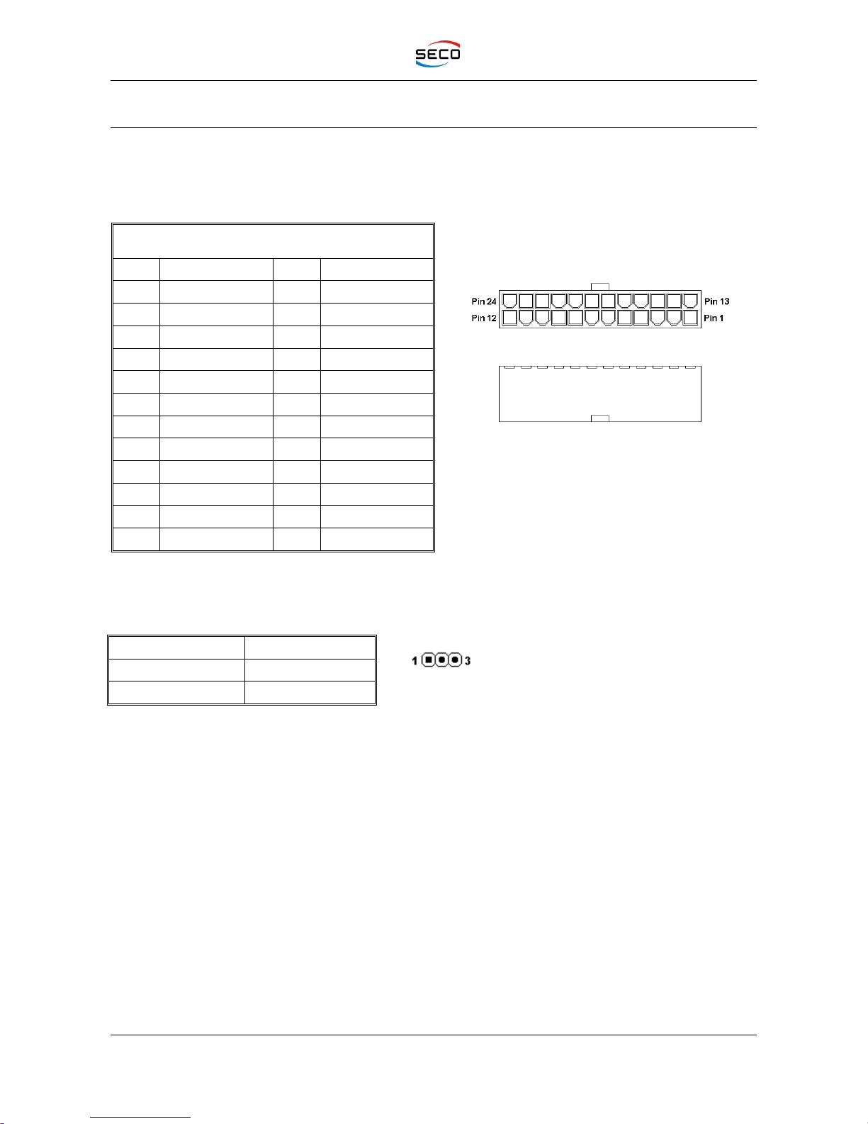
Power Connector is type Molex Mini-Fit Jr. connector, p/n 39-28-1243, or equivalent, with the pin-
out indicated in the following table (is the standard 24-pin ATX pin-out).
Power connector –CN30
Pin
Signal
Pin
Signal
1
+3.3V_S
13
+3.3V_S
2
+3.3V_S
14
---
3
GND
15
GND
4
+5V_S
16
PS_ON***
5
GND
17
GND
6
+5V_S
18
GND
7
GND
19
GND
8
PWGIN
20
---
9
+5VSB
21
+5V_S
10
+12V_S
22
+5V_S
11
+12V_S
23
+5V_S
12
+3.3V_S
24
GND
***PS_ON: this signal is present only if the board is configured, via JP6, to work in ATX mode. If
working in AT mode, this pin is connected directly to Ground
Selection of AT –ATX mode is made using this standard 2x2 pin header, P2.54mm.
JP11 configuration
Mode
1-2
ATX mode
2-3
AT mode
Three SMT LEDs are present near the Power Connector to indicate the state of Power Supply
Voltage.
Red Led, D22: +5V_S ON
Yellow Led, D23: +5VSB ON
Green Led, D24: +3.3V_S ON
There are also two small pushbuttons, M1 and M2, on board’s border near the mini PCI Express
slot, that are used, respectively, to reset or to turn on/off the power of the board.
2.4.1 RTC Battery
For the occurrences when the system (Carrier Board + Qseven®module) is not powered with an
external power supply, nor with an internal Smart Battery, on board there is a vertical battery
holder (CN28), for the use of standard coin battery type CR2032 with a nominal capacity of
220mAh, to supply, with a 3V voltage, the Real Time Clock and CMOS memory mounted on your
Qseven®module.
The batteries should only be replaced with devices of the same type. Always check the orientation
before inserting and make sure that they are aligned correctly and are not damaged or leaking.

SECOCQ7-mITX2.0
User Manual - Rev. First Edition: 1.0 - Last Edition: 1.0 - Author: S.B. - Reviewed by G.M.
Copyright © 2013 SECO S.r.l.
SECOCQ7-mITX2.0
Page 13
Never allow the batteries to become short-circuited during handling.
CAUTION: handling batteries incorrectly or with not-approved devices may present a risk of fire or
explosion.
Batteries supplied with SECOCQ7-mITX2.0 board are compliant to requirements of European
Directive 2006/66/EC regarding batteries and accumulators. When putting out of order SECOCQ7-
mITX2.0 board, remove the batteries from the board in order to collect and dispose them according
to the requirement of the same European Directive above mentioned. Even when replacing the
batteries, the disposal has to be made according to these requirements.

SECOCQ7-mITX2.0
User Manual - Rev. First Edition: 1.0 - Last Edition: 1.0 - Author: S.B. - Reviewed by G.M.
Copyright © 2013 SECO S.r.l.
SECOCQ7-mITX2.0
Page 14
Chapter 3 CONNECTORS
Connectors placement - Overview
Connectors overview
Connectors Description
SECOCQ7-mITX2.0
User Manual - Rev. First Edition: 1.0 - Last Edition: 1.0 - Author: S.B. - Reviewed by G.M.
Copyright © 2013 SECO S.r.l.
SECOCQ7-mITX2.0
Page 15
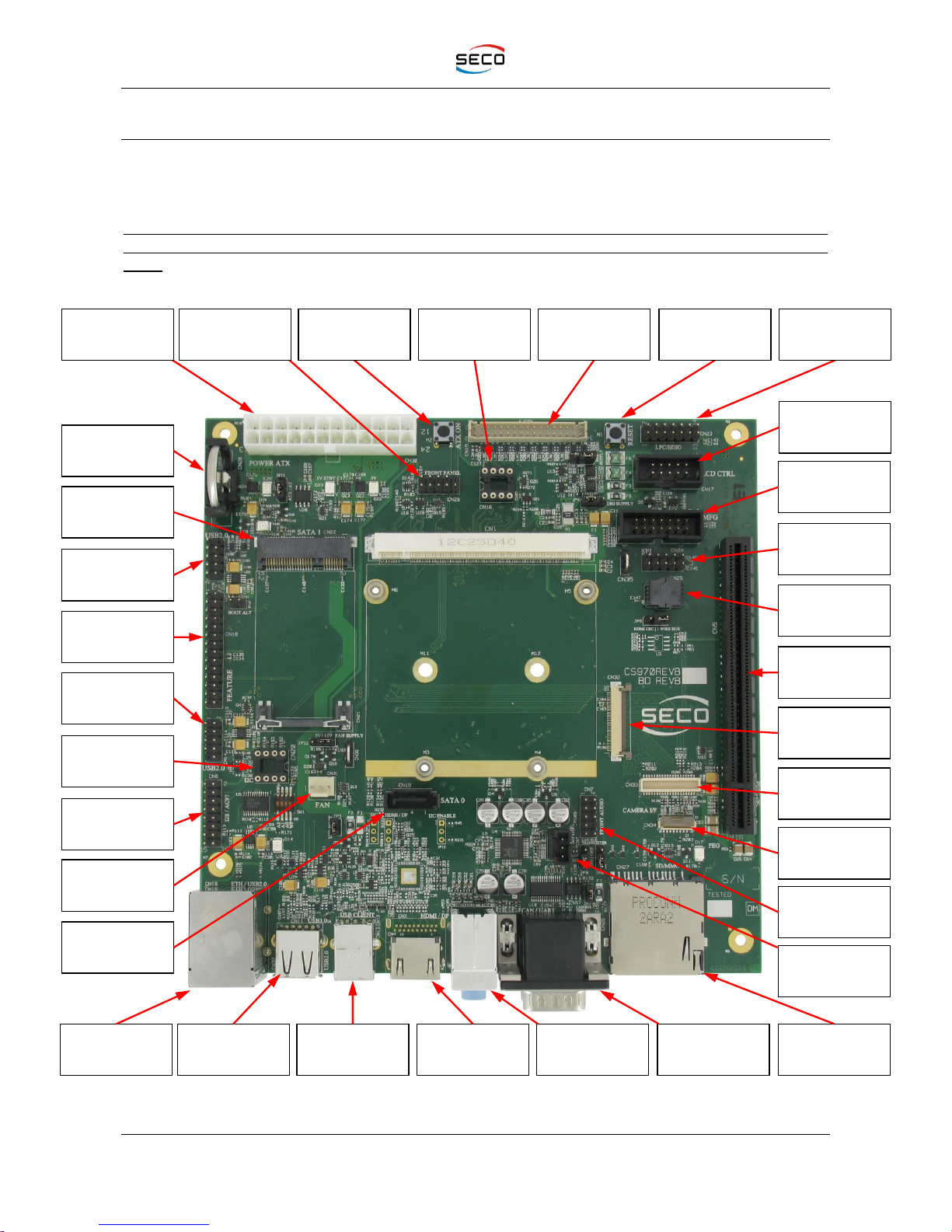
3.1 Connectors placement - Overview
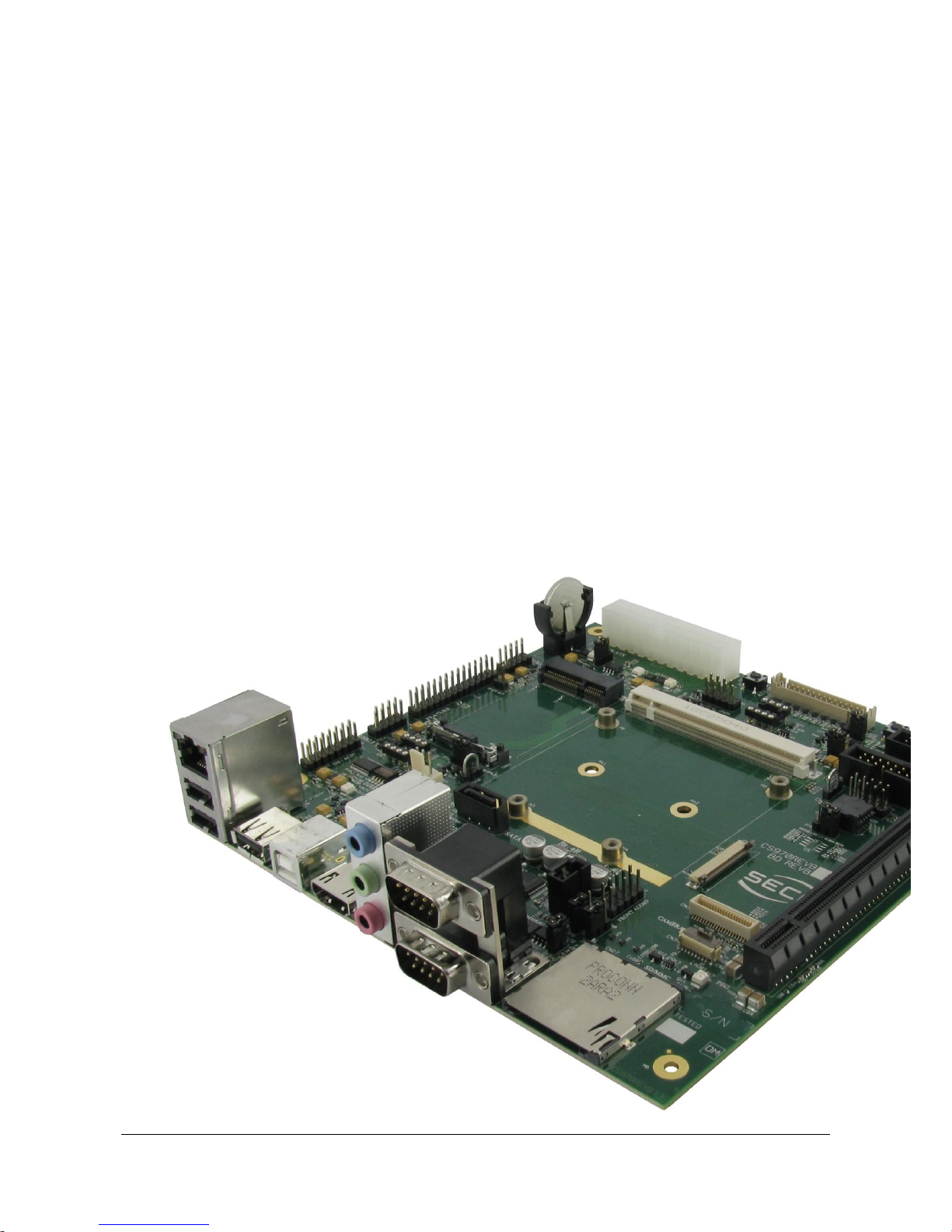
In the following picture, it is shown the connectors placement of SECOCQ7-mITX2.0 carrier board.
Standard connectors are placed on the same side of PCB, so that it is possible to place them on a
panel of an eventual enclosure.
PLEASE BE AWARE THAT, DEPENDING ON THE CONFIGURATION YOU PURCHASED, THE
APPAREANCE OF YOUR BOARD COULD BE SLIGHTLY DIFFERENT FROM THE FOLLOWING
ONE.
RTC Battery
holder
mSATA slot
USB2.0 ports
#6-7 Pin Header
Feature
connector
USB2.0 ports
#4-5 Pin Header
I2C EEPROM
Socket
I2C + I2S Pin
Header
FAN
connector
SATA
connector
USB3.0 or
USB2.0
connector
USB Client
connector
HDMI + optional
Display Port
Triple Audio Jack
CAN + RS-232
DB9 connectors
SD/MMC Slot
S/P-DIF
connector
2nd Audio
interface
External camera
interface
Backlight
connector
Manufacturer
connector
Qseven camera
interface
Gigabit Ethernet
+ Dual USB 2.0
CSI interface
PCI-e x4
interface
SPI Flash
socket
SPI
Pin Header
Front Header
interface
Power On
button
Display
EEPROM Socket
LCD (LVDS/eDP)
connector
Reset
button
LPC
Pin Header
ATX Power
Connector

SECOCQ7-mITX2.0
User Manual - Rev. First Edition: 1.0 - Last Edition: 1.0 - Author: S.B. - Reviewed by G.M.
Copyright © 2013 SECO S.r.l.
SECOCQ7-mITX2.0
Page 16
3.2 Connectors overview
3.2.1 Jumper Summary
Name
Description
Name
Description
JP1
DP_Aux-/HDMI_CTRL_DAT switch
JP8
JTAG/Debug UART switch1
JP2
DP_Aux+/HDMI_CTRL_CLK switch
JP9
JTAG/Debug UART switch2
JP3
USB1 Host/Client selector
JP10
BOOT_ALT# driving
JP4
LCD power rail selection
JP11
ATX/AT mode selection
JP5
Backlight power rail selection
JP12
FAN Voltage selection
JP6
OneWire/HDMI_CEC switch
JP13
HDMI/DVI display differentiation
JP7
CAN Bus termination
3.2.2 Connectors Summary
Name
Description
Name
Description
CN1
Qseven®connector
CN19
SATA connector
CN2
Manufacturer connector
CN20
I2C EEPROM socket
CN3
Optional DisplayPort + HDMI Combo
connector
CN22
mSATA slot
CN4
Optional Single HDMI connector
CN23
LPC pin header
CN5
PCI-e x 16 slot (PCI-e x4 electrical)
CN24
SPI pin header
CN6
Triple Audio Jack
CN25
SPI Flash Socket
CN7
2nd MicIn + 2nd LineIn Audio
CN26
CAN + RS-232 Double DB9 connector
CN8
I2C + I2S Audio interface
CN27
SD/MMC Slot
CN9
SPDIF Out
CN28
RTC Battery Holder
CN10
USB2.0 ports 2-3 + Gigabit Ethernet
CN29
Front Header interface
CN11
Optional USB 3.0 type A port
CN30
ATX Power Connector
CN12
Optional USB3.0 type B port
CN31
FAN connector
CN13
Optional USB2.0 type B port
CN32
Qseven Camera Interface
CN14
Optional USB 2.0 ports #4-5 pin header
CN33
External Camera Interface
CN15
LVDS/eDP connector
CN34
CSI interface
CN16
Display EEPROM socket
CN37
Optional USB 2.0 type A port #0
CN17
Backlight connector
CN38
Optional USB 2.0 ports# 6-7
CN18
Feature connector

SECOCQ7-mITX2.0
User Manual - Rev. First Edition: 1.0 - Last Edition: 1.0 - Author: S.B. - Reviewed by G.M.
Copyright © 2013 SECO S.r.l.
SECOCQ7-mITX2.0
Page 17
3.3 Connectors Description
3.3.1 Qseven®Connector
According to Qseven®specifications, for the insertion of the CPU module there is a standard 230-
pin MXM connector, height 6.5mm, type LOTES AAA-MXM-006-K01.
Please notice that on Qseven connectors are available some signals, defined as RSVD_xxx, which
are defined, per Qseven®specifications, as RESERVED signals. These signals can be carried out
directly to ZIF CSI Camera connector CN34, depending on your board’s configuration.
Please also refer to Qseven®specifications Rel. 2.0 for a complete description of each signal.
Qseven®MXM Connector - CN1
Pin
Signal
Pin
Signal
1
GND
2
GND
3
GBE_MDI3-
4
GBE_MDI2-
5
GBE_MDI3+
6
GBE_MDI2+
7
GBE_LINK100#
8
GBE_LINK1000#
9
GBE_MDI1-
10
GBE_MDI0-
11
GBE_MDI1+
12
GBE_MDI0+
13
GBE_LINK#
14
GBE_ACT#
15
GBE_CTREF
16
SUS_S5#
17
WAKE#
18
SUS_S3#
19
SUS_STAT#
20
PWRBTN#
21
SLP_BTN#
22
LID_BTN#
23
GND
24
GND
25
GND
26
PWGIN
27
BATLOW#
28
RSTBTN#
29
SATA0_Tx+
30
SATA1_Tx+
31
SATA0_Tx-
32
SATA1_Tx-
33
SATA_ACT#
34
GND
35
SATA0_Rx+
36
SATA1_Rx+
37
SATA0_Rx-
38
SATA1_Rx-
39
GND
40
GND
41
BOOT_ALT# (*)
42
SDIO_CLK#
43
SDIO_CD#
44
SDIO_LED
45
SDIO_CMD
46
SDIO_WP
47
SDIO_PWR#
48
SDIO_DAT1
49
SDIO_DAT0
50
SDIO_DAT3
51
SDIO_DAT2
52
SDIO_DAT5
53
SDIO_DAT4
54
SDIO_DAT7
55
SDIO_DAT6
56
RSVD
57
GND
58
GND
59
HDA_SYNC/I2S_WS
60
SMB_CLK
61
HDA_RST#/I2S_RST#
62
SMB_DAT
63
HDA_BITCLK/I2S_CLK
64
SMB_ALERT#
65
HDA_SDI/I2S_SDI
66
GP0_I2C_CLK
67
HDA_SDO/I2S_SDO
68
GP0_I2C_DAT
SECOCQ7-mITX2.0
User Manual - Rev. First Edition: 1.0 - Last Edition: 1.0 - Author: S.B. - Reviewed by G.M.
Copyright © 2013 SECO S.r.l.
SECOCQ7-mITX2.0
Page 18
69
THRM#
70
WDTRIG#
71
THRMTRIP#
72
WDOUT
73
GND
74
GND
75
USB_P7-/USB_SSTX0-
76
USB_P6-/USB_SSRX0-
77
USB_P7+/USB_SSTX0+
78
USB_P6+/USB_SSRX0+
79
USB_6_7_OC#
80
USB_4_5_OC#
81
USB_P5-/USB_SSTX1-
82
USB_P4-/USB_SSRX1-
83
USB_P5+/USB_SSTX1+
84
USB_P4+/USB_SSRX1+
85
USB_2_3_OC#
86
USB_0_1_OC#
87
USB_P3-
88
USB_P2-
89
USB_P3+
90
USB_P2+
91
USB_CC
92
USB_ID
93
USB_P1-
94
USB_P0-
95
USB_P1+
96
USB_P0+
97
GND
98
GND
99
eDP0_TX0+/LVDS_A0+
100
eDP1_TX0+/LVDS_B0+
101
eDP0_TX0-/LVDS_A0-
102
eDP1_TX0-/LVDS_B0-
103
eDP0_TX1+/LVDS_A1+
104
eDP1_TX1+/LVDS_B1+
105
eDP0_TX1-/LVDS_A1-
106
eDP1_TX1-/LVDS_B1-
107
eDP0_TX2+/LVDS_A2+
108
eDP1_TX2+/LVDS_B2+
109
eDP0_TX2-/LVDS_A2-
110
eDP1_TX2-/LVDS_B2-
111
LVDS_PPEN
112
LVDS_BLEN
113
eDP0_TX3+/LVDS_A3+
114
eDP1_TX3+/LVDS_B3+
115
eDP0_TX3-/LVDS_A3-
116
eDP1_TX3-/LVDS_B3-
117
GND
118
GND
119
eDP0_AUX+/LVDS_A_CLK+
120
eDP1_AUX+/LVDS_B_CLK+
121
eDP0_AUX-/LVDS_A_CLK-
122
eDP1_AUX-/LVDS_B_CLK-
123
LVDS_BLT_CTRL
124
GP_1-Wire_Bus
125
LVDS_DID_DAT
126
eDP0_HPD#
127
LVDS_DID_CLK
128
eDP1_HPD#
129
CAN0_TX
130
CAN0_RX
131
DP_LANE3+/TMDS_CLK+
132
RSVD_132
133
DP_LANE3-/TMDS_CLK-
134
RSVD_134
135
GND
136
GND
137
DP_LANE1+/TMDS_LANE1+
138
DP_AUX+
139
DP_LANE1-/TMDS_LANE1-
140
DP_AUX-
141
GND
142
GND
143
DP_LANE2+/TMDS_LANE0+
144
RSVD_144
145
DP_LANE2-/TMDS_LANE0-
146
RSVD_146
147
GND
148
GND
149
DP_LANE0+/TMDS_LANE2+
150
HDMI_CTRL_DAT
151
DP_LANE0-/TMDS_LANE2-
152
HDMI_CTRL_CLK
153
DP_HDMI_HPD#
154
RSVD_154
155
PCIE_CLK_REF+
156
PCIE_WAKE#
157
PCIE_CLK_REF-
158
PCIE_RST#
159
GND
160
GND

SECOCQ7-mITX2.0
User Manual - Rev. First Edition: 1.0 - Last Edition: 1.0 - Author: S.B. - Reviewed by G.M.
Copyright © 2013 SECO S.r.l.
SECOCQ7-mITX2.0
Page 19
161
PCIE3_TX+
162
PCIE3_RX+
163
PCIE3_TX-
164
PCIE3_RX-
165
GND
166
GND
167
PCIE2_TX+
168
PCIE2_RX+
169
PCIE2_TX-
170
PCIE2_RX-
171
UART0_TX
172
UART0_RTS#
173
PCIE1_TX+
174
PCIE1_RX+
175
PCIE1_TX-
176
PCIE1_RX-
177
UART0_RX
178
UART0_CTS#
179
PCIE0_TX+
180
PCIE0_RX+
181
PCIE0_TX-
182
PCIE0_RX-
183
GND
184
GND
185
LPC_AD0 / GPIO0
186
LPC_AD1 / GPIO1
187
LPC_AD2 / GPIO2
188
LPC_AD3 / GPIO3
189
LPC_CLK / GPIO4
190
LPC_FRAME# / GPIO5
191
SERIRQ / GPIO06
192
LPC_LDRQ# / GPIO7
193
Vcc_RTC
194
SPKR
195
FAN_TACHOIN
196
FAN_PWMOUT
197
GND
198
GND
199
SPI_MOSI
200
SPI_CS0#
201
SPI_MISO
202
SPI_CS1#
203
SPI_SCK
204
MFG_NC4
205
+5VSB
206
+5VSB
207
MFG_NC0
208
MFG_NC2
209
MFG_NC1
210
MFG_NC3
211
Vcc
212
Vcc
213
Vcc
214
Vcc
215
Vcc
216
Vcc
217
Vcc
218
Vcc
219
Vcc
220
Vcc
221
Vcc
222
Vcc
223
Vcc
224
Vcc
225
Vcc
226
Vcc
227
Vcc
228
Vcc
229
Vcc
230
Vcc
(*)BOOT_ALT# Signal: this signal can be necessary to the Qseven®Module to disable module’s
onboard BIOS (x86 modules) or enable different boot devices (most of all, for ARM modules).
For this reason, on SECOCQ7-mITX2.0 carrier board there is a dedicated jumper, JP10, which
allows external driving of BOOT_ALT# signal.
JP10
BOOT_ALT# value
Inserted
Low
Not inserted
High
Please refer to your Qseven®module’s User Manual to determine the meaning/usage of this
signal.

SECOCQ7-mITX2.0
User Manual - Rev. First Edition: 1.0 - Last Edition: 1.0 - Author: S.B. - Reviewed by G.M.
Copyright © 2013 SECO S.r.l.
SECOCQ7-mITX2.0
Page 20
3.3.2 LVDS / embedded Display Port Connector
SECOCQ7-mITX2.0 board can be interfaced to LCD displays using its LVDS/eDP interface, which
allows the connection of displays with a colour depth of 18 or 24 bit, single or dual channel.
Please notice that the effective support of this kind of displays, and the effective kind of interface,
depends only by the Qseven®module used with the carrier board, it is not a feature dependent
from the carrier board itself. The pin-out of this connector is given according to Qseven®
specifications, so that the carrier board is ready for the use of any Qseven®module that follows
those specifications. Please refer to your CPU Module’s user manual for the details regarding the
panel supported (LVDS or eDP, Single or Dual Channel, and so on).
For the connection, a connector type JST B34B-PHDSS or equivalent (2 x 17p, male, straight, P2,
low profile, polarised) is provided, with the following pin-out.
LVDS / eDP Connector - CN15
Pin
Signal
Pin
Signal
2
LVDS_DID_DAT
1
LVDS_DID_CLK
4
---
3
---
6
GND
5
eDP0_TX0-/LVDS_A0-
8
eDP0_TX0+/LVDS_A0+
7
PANEL_VDD_ENABLE
10
eDP0_TX1-/LVDS_A1-
9
eDP0_TX1+/LVDS_A1+
12
LVDS_BLEN
11
eDP0_TX2+/LVDS_A2+
14
eDP0_TX2-/LVDS_A2-
13
eDP0_HPD
16
eDP0_AUX-/LVDS_A_CLK-
15
eDP0_AUX+/LVDS_A_CLK+
18
LVDS_BLT_CTRL
17
eDP0_TX3+/LVDS_A3+
20
eDP0_TX3-/LVDS_A3-
19
GND
22
eDP1_TX0-/LVDS_B0-
21
eDP1_TX0+/LVDS_B0+
24
GND
23
eDP1_TX1-/LVDS_B1-
26
eDP1_TX1+/LVDS_B1+
25
GND
28
eDP1_TX2-/LVDS_B2-
27
eDP1_TX2+/LVDS_B2+
30
GND
29
eDP1_AUX+/LVDS_B_CLK+
32
eDP1_AUX-/LVDS_B_CLK-
31
eDP1_HPD
34
eDP1_TX3+/LVDS_B3+
33
eDP1_TX3-/LVDS_B3-
3.3.3 Backlight connector
If desired, onboard there is a small connector intended for taking out power supplies, for an
eventual panel backlight module.
Backlight connector CN17 is an IDC connector, dual row, 10 pin, p2.54 mm connector, type
MATSUYAMA LN210 or equivalent.
Backlight Connector –CN17
Pin
Signal
Pin
Signal
1
SW_VDD (Fuse protected)
2
SW_BACK (Fuse protected)
3
+5V_S (Fuse protected)
4
+12V_S (Fuse protected)
5
PANEL_VDD_ENABLE
6
LVDS_BLEN
7
Analogic_Dimming
8
LVDS_BLT_CTRL
9
GND
10
GND
Table of contents
Other Seco Motherboard manuals


