300S v
Introduction
Introduction
Software Version
The software version is shown on the initial power up screen.
300S
DRO axis availability.
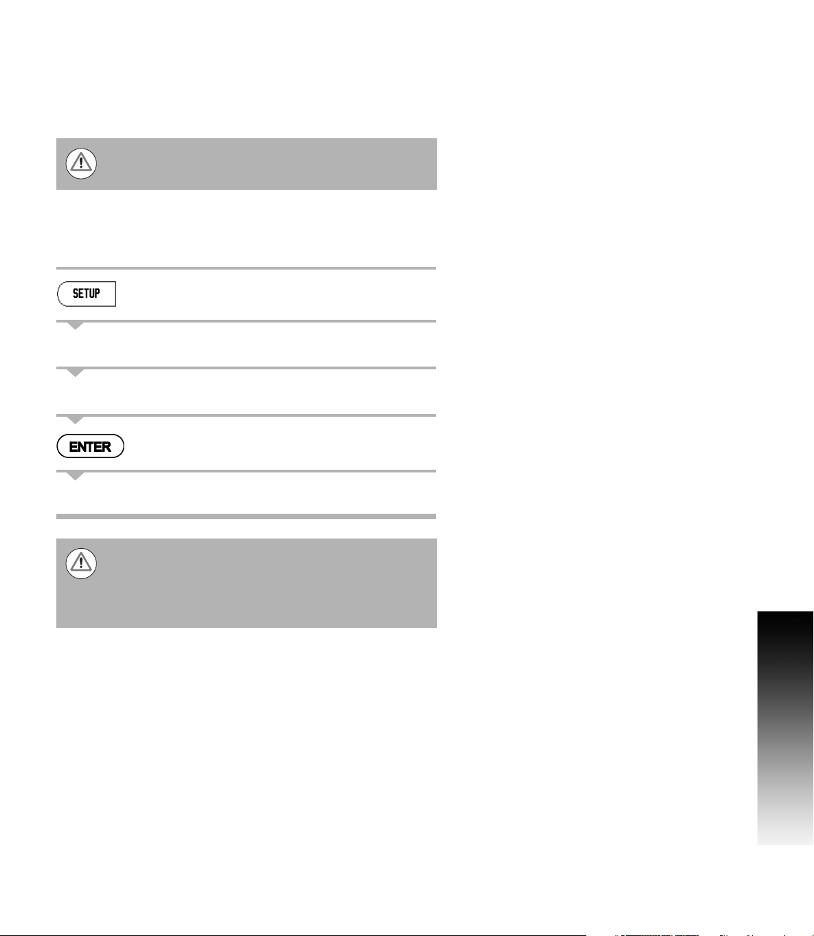
Symbols within Notes
Every note is marked with a symbol on the left indicating to the
operator the type, and/or potential severity of the note.
300S Fonts
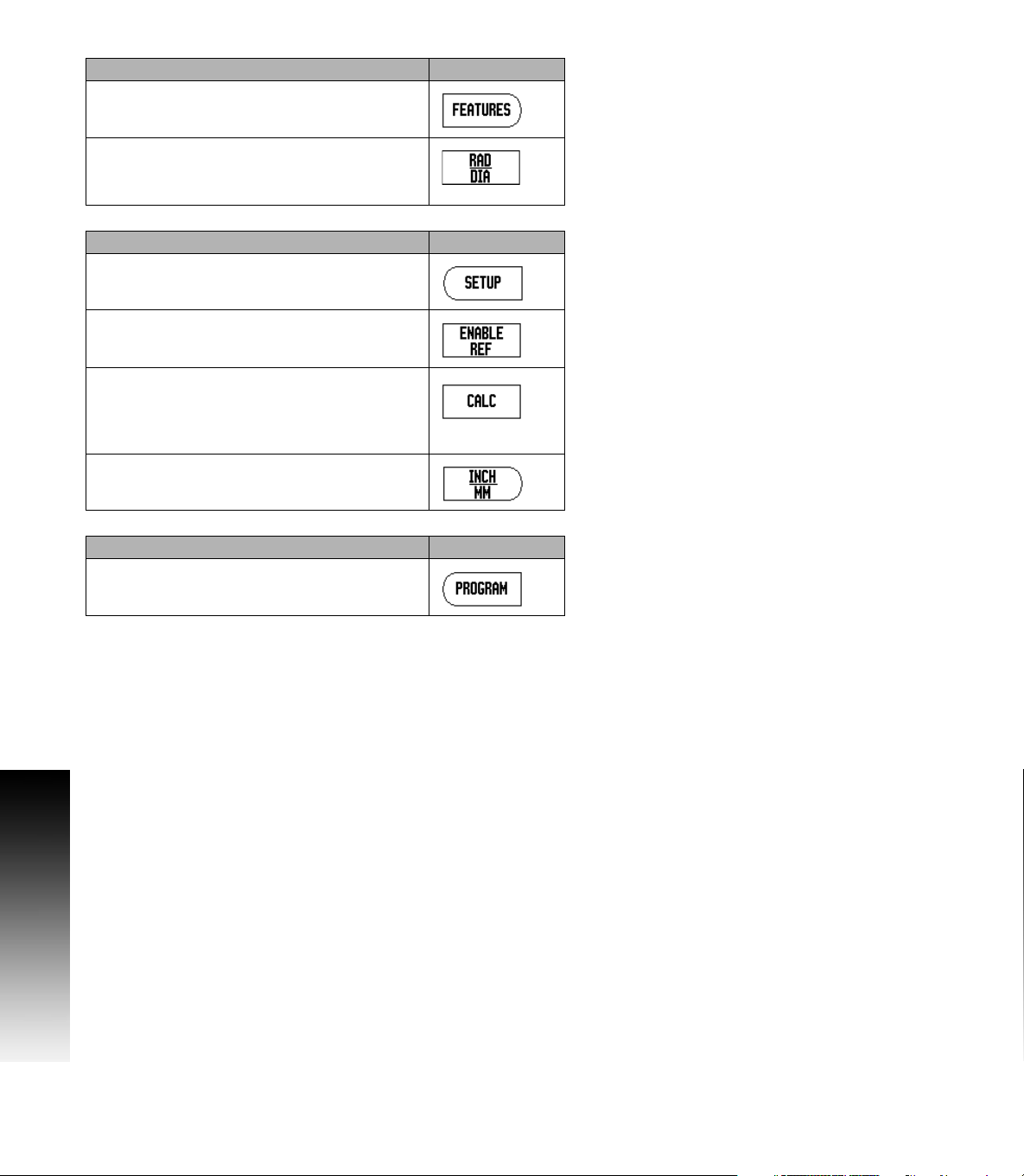
The following shows how soft keys, and hard keys are represented
within the text of this manual:
Soft keys - SETUP soft key
Hard keys - ENTER hard key
This User's Manual covers the functions of the 300S for
both milling, and turning applications. Operational
information is arranged in three sections: General
Operations, Mill Specific Operations, and Turn
Specific Operations.
The 300S Color DRO is available in two, three, and four
axis form. The 4 axis 300S DRO is used through out this
manual for illustration, and description of function keys.
General Information
e.g. on the behavior of the 300S.
Warning
e.g. when a special tool is required for a function.
Damage - Risk of electric shock
e.g. when opening a housing.