Siemens INOX PRO SIMATIC IFP1900 Administrator guide

Siemens AG
Digital Industries
Postfach 48 48
90026 NÜRNBERG
GERMANY
A5E35751632-AC
Ⓟ
07/2019 Subject to change
Copyright © Siemens AG 2019.
All rig
hts reserved
Legal information
Warning notice system
This manual contains notices you have to observe in order to ensure your personal safety, as well as to prevent
damage to property. The notices referring to your personal safety are highlighted in the manual by a safety alert
symbol, notices referring only to property damage have no safety alert symbol. These notices shown below are
graded according to the degree of danger.
DANGER
indicates that death or severe personal injury will result if proper precautions are not taken.
WARNING
indicates that death or severe personal injury may result if proper precautions are not taken.
CAUTION
indicates that minor personal injury can result if proper precautions are not taken.
NOTICE
indicates that property damage can result if proper precautions are not taken.
If more than one degree of danger is present, the warning notice representing the highest degree of danger will
be used. A notice warning of injury to persons with a safety alert symbol may also include a warning relating to
property damage.
Qualified Personnel
The product/system described in this documentation may be operated only by personnel qualified for the specific
task in accordance with the relevant documentation, in particular its warning notices and safety instructions.
Qualified personnel are those who, based on their training and experience, are capable of identifying risks and
avoiding potential hazards when working with these products/systems.
Proper use of Siemens products
Note the following:
WARNING
Siemens products may only be used for the applications described in the catalog and in the relevant technical
documentation. If products and components from other manufacturers are used, these must be recommended
or approved by Siemens. Proper transport, storage, installation, assembly, commissioning, operation and
maintenance are required to ensure that the products operate safely and without any problems. The permissible
ambient conditions must be complied with. The information in the relevant documentation must be observed.
Trademarks
All names identified by ® are registered trademarks of Siemens AG. The remaining trademarks in this publication
may be trademarks whose use by third parties for their own purposes could violate the rights of the owner.
Disclaimer of Liability
We have reviewed the contents of this publication to ensure consistency with the hardware and software
described. Since variance cannot be precluded entirely, we cannot guarantee full consistency. However, the
information in this publication is reviewed regularly and any necessary corrections are included in subsequent
editions.

IFP1900 INOX PRO
Compact Operating Instructions, 07/2019, A5E35751632-AC 3
Preface
Validity
This document applies to devices with the designation IFP1900 INOX PRO, article numbers:
●IFP1900 INOX PRO Stand variant with operator controls, article number
6AV7484-6AB00-0AA0
●IFP1900 INOX PRO Support arm variant, article number with operator controls, article
number 6AV7484-6AB10-0AA0
●IFP1900 INOX PRO Stand variant without operator controls, article number
6AV7484-6AB01-0AA0
●IFP1900 INOX PRO Support arm variant, article number 6AV7484-6AB11-0AA0
In relation to the operation, the IFP1900 INOX PRO is identical with the base unit IFP1900
Touch Standard.
This document describes the mechanical and electrical differences between the device and
the base device IFP1900 Touch Standard.
The notes contained in this document take precedence over the information contained in the
documentation of the basic device, in the release notes and in the online help.
You can find the documentation of the basic device on the Internet at the following address:
Operating Instructions Industrial Flat Panels IFP, IFP PRO, IFP ETH
(http://support.automation.siemens.com/WW/view/en/65288650)
Conventions
The term "device" is also used instead of the product designation in this document.
"Windows 7" is used as an abbreviation for "Windows 7 Ultimate".
Figures
This document contains figures of the device described. The figures can deviate from the
particularities of the delivered device.

IFP1900 INOX PRO
4 Compact Operating Instructions, 07/2019, A5E35751632-AC
Table of contents
Preface........................................................................................................................................ 3
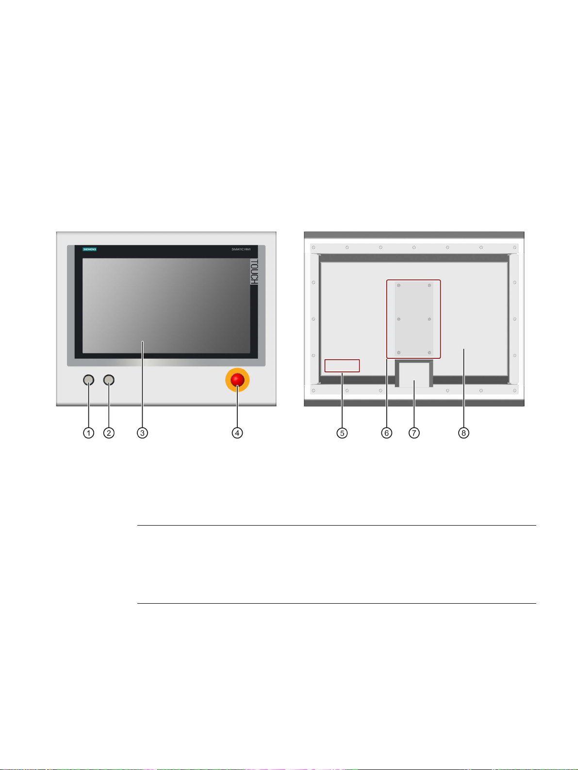
1 Product description ....................................................................................................................... 5
2 Safety instructions......................................................................................................................... 9
2.1 Intended use ....................................................................................................................... 9
2.2 General safety instructions .................................................................................................. 9
2.3 Notes about usage .............................................................................................................11
3 Installing the device..................................................................................................................... 12
3.1 Permitted mounting positions..............................................................................................12
3.2 Mounting and connecting the device...................................................................................12
3.3 Dismantling the device .......................................................................................................18
4 Commissioning the device ........................................................................................................... 19
5 Maintaining and repairing the device ............................................................................................. 20
5.1 General information on maintenance and servicing.............................................................20
5.2 Cleaning.............................................................................................................................20
5.2.1 Cleaning the device............................................................................................................20
5.2.2 Clean screen......................................................................................................................21
5.2.3 Chemical Resistance..........................................................................................................22
5.2.4 Working with stainless steel surfaces..................................................................................22
5.3 Resetting the device to factory settings...............................................................................24
5.4 Repair ................................................................................................................................24
6 Specifications ............................................................................................................................. 25
6.1 Certificates and approvals ..................................................................................................25
6.2 Guidelines and declarations ...............................................................................................26
6.3 Dimension drawings ...........................................................................................................27
6.3.1 IFP1900 INOX PRO ...........................................................................................................27
6.3.2 Mechanical interface of the device......................................................................................28
6.4 Technical specifications......................................................................................................28
6.4.1 General technical specifications .........................................................................................28
6.4.2 Environmental conditions....................................................................................................30
6.5 Description of the interfaces ...............................................................................................31
6.5.1 Pin assignment of the internal terminal strip........................................................................31
A Technical support........................................................................................................................ 32
A.1 Service and support ...........................................................................................................32

IFP1900 INOX PRO
Compact Operating Instructions, 07/2019, A5E35751632-AC 5
Product description
1
The IFP1900 INOX PRO devices are mounted to a support arm or stand by means of the
mechanical interface. The IFP1900 INOX PRO devices are not intended for installation in a
control cabinet.
The figures below show the front view and rear view using a device with operator controls
and stand mounting as an example.
①
Illuminated pushbutton
1
"left" with green LED
⑤
Position of nameplate and approvals
②
Illuminated pushbutton
1
"right" with red LED
⑥
Connection compartment
③
Display with touch screen
⑦
Mechanical interface for fastening
④
EMERGENCY OFF button
1
⑧
Rear panel
1Only for devices with operator controls
Note
EMERGENCY OFF button
The connections of the EMERGENCY OFF button are wired to pins
1-4 of the terminal strip
in the connection compartment.
The EMERGENCY OFF button is not connected with the electronics inside the device.

Product description
IFP1900 INOX PRO
6Compact Operating Instructions, 07/2019, A5E35751632-AC
Features
Properties of the IFP1900 INOX PRO:
•
Enclosure material:
INOX stainless steel, material number 1.4301
•
Sealing material:
FPM (fluorinated rubber)
•
Front membrane:
Polyester
-based
•
Degree of protection:
IP66 all
-round
•
Front operator controls:
2 illuminated pushbuttons, 1 EMERGENCY OFF button, wired to
internal terminal strip
1
•
Mechanical interface:
For stand mounting, analogous for support arm mounting
1Internal plug-in terminal strip only for devices with operator controls, pin assignment of the
internal terminal strip, see section "Pin assignment of the internal terminal strip (Page 31)"
Scope of delivery
●1 x IFP1900 INOX PRO
●1 x 2-pin connecting terminal for the 24 V DC power supply
●1 x 20-pin connecting terminal, matching the internal 20-pin terminal strip of the device
●1 x seal for mechanical interface
Accessories
Note
Accessories are intended only for the INOX devices listed above and not in general for other
PRO devices (standard).
Mounting kit for stand mounting
A mounting kit is available for pedestal mounting of the device. Mounting kit contents:
●1 stainless steel tube with flange: Length 500 mm, outer diameter 48.3 mm, inner
diameter 40 mm.
The mechanical interface of the stainless steel tube with flange fits the mechanical
interface of the device.
●4 hexagon screws M5×25 made of stainless steel
●1 flat seal
Article number 6AV7675-1GB00-0AA0

Product description
IFP1900 INOX PRO
Compact Operating Instructions, 07/2019, A5E35751632-AC 7
Mounting kit for support arm mounting
A mounting kit is available for support arm mounting of the device. Mounting kit contents:
●1 stainless steel tube with flange: Length 500 mm, outer diameter 48.3 mm, inner
diameter 40 mm.
The mechanical interface of the stainless steel tube with flange fits the mechanical
interface of the device.
●1 adapter support arm
●8 hexagon screws M5×20 made of stainless steel
●2 flat seals
Article number 6AV7675-1GB10-0AA0
Service pack
The service pack contains:
●1 spare seal for the connection compartment cover of the device
●6 screws for the connection compartment cover of the device
●1 spare seal for the mechanical interface of the device
●4 screws for fastening the stainless steel tube with flange from a mounting kit to the
mechanical interface of the device
●1 connecting terminal for the power supply
●1 terminal block for the terminal strip in the connection compartment
●Documentation
Article number 6AV7675-1JD20-0AA0
Service pack 2, only in combination with the service manual
The service pack 2 contains:
●1 spare seal for the rear panel of the device
●4 spare screws for the rear panel of the device
●1 spare seal for the mechanical interface of the device
●4 screws for fastening the stainless steel tube with flange from a mounting kit to the
mechanical interface of the device
●1 connecting terminal for the power supply
●Documentation
Article number 6AV7675-1JD21-0AA0

Product description
IFP1900 INOX PRO
8Compact Operating Instructions, 07/2019, A5E35751632-AC
Service pack 3, in connection with devices for support arm mounting
Service pack 3 contains:
●1 spare seal for the connection compartment cover of the device
●1 spare seal for the mechanical interface of the device
●1 spare seal for support arm mounting
●8 screws M5 x 20 mm for support arm mounting
●6 screws for the connection compartment cover of the device
●1 connecting terminal for the power supply
●1 terminal block for the terminal strip in the connection compartment
●Documentation
Article number 6AV7675-1JD20-1AA0
Service manual
A service manual that describes the following maintenance work is available for the IFP1900
INOX PRO:
●Replacing the seal of the rear panel
●Replacing defective operator controls in the device front
●Converting a device for stand mounting into a device for support arm mounting and vice
versa
WARNING
Opening the device and working on the opened device may only be carried out by qualified
and correspondingly trained personnel
The service manual describes, amongst other points, the opening of the device and
working on the wiring or on electronic components in the inside of the device. Injuries or
material damage may result if the work is not carried out correctly.
The work described in the service manual may only be carried out by qualified specialist
personnel who have been trained correspondingly by Siemens.
The service manual is available online under "Product Support" next to this document in the
same branch of the product tree.

IFP1900 INOX PRO
Compact Operating Instructions, 07/2019, A5E35751632-AC 9
Safety instructions
2
2.1 Intended use
The IFP1900 INOX PRO touch screen front panel devices are designed to be used for high-
performance visualization tasks (operator control and monitoring) and in ambient conditions
such as those found in the food, beverage and pharmaceutical industries.
WARNING
Improper use can endanger safety.
Improper use of the device endangers safety and can result in personal injury or damage to
property.
Any use deviating from the intended use is not permitted.
Operate the device only in accordance with its intended use.
Also see the information in the section "Cleaning the device (Page 20)".
Particular attention has been paid during design of the HMI devices to ensure that the front
panel is easy to clean and can be disinfected when needed. The devices with stainless steel
front have therefore been developed according to DIN EN 1672-2 "Food Processing
Machinery - Safety and Hygiene Requirements".
2.2 General safety instructions
WARNING
Performing a function test when installing the device in machines or systems
Following the results of a risk analysis, additional protection equipment on the machine or
the system is necessary to avoid endangering persons. In particular, the programming,
parameter assignment and wiring of the inserted I/O must be executed in accordance with
the safety performance identified by the necessary risk analysis (SIL, PL or Cat.). The
intended use of the device has to be ensured.
The proper use of the device has to be verified with a function test on the system. These
tests help you to identify programming, parameter assignment and wiring errors. The test
results have to be recorded and, if necessary, entered into the safety verification
documents.

Safety instructions
2.2 General safety instructions
IFP1900 INOX PRO
10 Compact Operating Instructions, 07/2019, A5E35751632-AC
Defective touch screen
WARNING
Risk of explosion, personal injury or material damage in the case of a defective touch
screen
The application of excessive force to the device front can destroy the device touch screen,
for example, piercing the front membrane or breaking the touch screen carrier plate. There
is a risk of explosion, injury and food contamination with additional consequential and
health damage.
Make sure that excessive force cannot be applied to the device front.
If the device touch screen is defective, decommission the affected machine immediately
and replace the device at once. When replacing the device, please note the chapter
"Repair (Page 24)".
ESD
Electrostatically sensitive components include almost all electrical, electronic, optoelectronic
and electromechanical components. These components are sensitive to overvoltage for
technical reasons and their function may be impaired or destroyed by electrostatic discharge.
Observe the regulations governing the handling of ESD components.
Industrial Security
Siemens provides products and solutions with industrial security functions that support the
secure operation of plants, systems, machines and networks.
In order to protect plants, systems, machines and networks against cyber threats, it is
necessary to implement – and continuously maintain – a holistic, state-of-the-art industrial
security concept. Siemens’ products and solutions constitute one element of such a concept.
Customers are responsible for preventing unauthorized access to their plants, systems,
machines and networks. Such systems, machines and components should only be
connected to an enterprise network or the internet if and to the extent such a connection is
necessary and only when appropriate security measures (e.g. firewalls and/or network
segmentation) are in place.
For additional information on industrial security measures that may be implemented, please
visit (http://www.siemens.com/industrialsecurity).
Siemens’ products and solutions undergo continuous development to make them more
secure. Siemens strongly recommends that product updates are applied as soon as they are
available and that the latest product versions are used. Use of product versions that are no
longer supported, and failure to apply latest updates may increase customer’s exposure to
cyber threats.
To stay informed about product updates, subscribe to the Siemens Industrial Security RSS
Feed under (http://www.siemens.com/industrialsecurity).

Safety instructions
2.3 Notes about usage
IFP1900 INOX PRO
Compact Operating Instructions, 07/2019, A5E35751632-AC 11
Disclaimer for third-party software updates
This product includes third-party software. Siemens AG only provides a warranty for
updates/patches of the third-party software, if these have been distributed as part of a
Siemens software update service contract or officially released by Siemens AG. Otherwise,
updates/patches are undertaken at your own risk. You can find more information about our
Software Update Service offer on the Internet at Software Update Service
(http://www.automation.siemens.com/mcms/automation-software/en/software-update-
service).
Notes on protecting administrator accounts
A user with administrator privileges has extensive access and manipulation options in the
system.
Therefore, ensure there are adequate safeguards for protecting the administrator accounts
to prevent unauthorized changes. To do this, use secure passwords and a standard user
account for normal operation. Other measures, such as the use of security policies, should
be applied as needed.
2.3 Notes about usage
CAUTION
Safety-relevant mechanisms not visible or operable
Position the device in such a manner that safety-related mechanisms such as a mains
isolation switch remain visible, accessible and operable.
NOTICE
HMI device approved for indoor use only
The HMI device may be damaged if operated outdoors.
Operate the HMI device indoors only ("Indoor use only").
Note
Operate the device only in a normal atmospheric environment
The technical characteristics of the device described in the operating instructions are
guaranteed if you operate the device in normal ambient air conditions with usual air
composition.

IFP1900 INOX PRO
12 Compact Operating Instructions, 07/2019, A5E35751632-AC
Installing the device
3
3.1 Permitted mounting positions
The device may only be operated in landscape format with a maximum inclination of ±30° to
the vertical.
Permissible ambient temperature: 0 ... 45 °C
3.2 Mounting and connecting the device
This section describes how to mount and connect the device correctly, using stand mounting
as an example. Mounting on a support arm is carried out in the same way. All the work steps
in this chapter have to be carried out sequentially for complete mounting of the device.
Requirement
●A stand with a mechanical interface suitable for the mechanical interface of the device;
see section "Mechanical interface of the device (Page 28)".
●The following lines are routed through the stand:
–Protective conductor, minimum cross-section of 2.5 mm2
–Lines for the external power supply, voltage-free
–Lines for the front operator controls
–All required data lines
●Four hexagon screws M5 according to screw standard ISO 4017, material X5CrNi18-10
The length of the screws have to be dimensioned so that the penetration depth of the
screw thread in the device-side flange lies in the range of 6 to 10 mm.

Installing the device
3.2 Mounting and connecting the device
IFP1900 INOX PRO
Compact Operating Instructions, 07/2019, A5E35751632-AC 13
Opening the connection compartment and installing the device
Note
The device is fastened to a stand or a support arm via the mechanical interface with four
screws.
Siemens AG assumes no liability for the consequences of a faulty installation.
WARNING
The device must be mounted securely
Inadequately dimensioned fastening material may cause the device to fall down. Serious
bodily injury may result.
Make sure that fasteners are adequately dimensioned during installation of the device.
Make sure to consider the weight of the device and the forces acting on the device when
dimensioning the fasteners. This applies in particular to dynamic load of the device.
Observe any further statutory specifications applying at the location of use of the device
and further applicable regulations with regard to the fastening of the device.
NOTICE
Placing the device on its front can damage operator controls
If you place the device on its front before or during the installation, the operator controls on
the front can be damaged.
Place the device on a soft and elevated surface so that the front operator controls do not
contact the working area and are not damaged.

Installing the device
3.2 Mounting and connecting the device
IFP1900 INOX PRO
14 Compact Operating Instructions, 07/2019, A5E35751632-AC
Procedure
1. Open the connection compartment. To do so, remove the 6 screws on the device rear
that are marked in the following figure and remove the connection compartment cover
and associated seal.
2. Place the supplied seal for the mechanical interface with its smooth side onto the stand.
Center the openings of the seal and of the mechanical interface of the stand.
3. Route the lines from the stand through the opening of the mechanical interface of the
device into the connection compartment.
4. Place the mechanical interface of the device onto the mechanical interface of the stand.
Take the following into account:
–The seal has to lie exactly in the mechanical interface of the device.
–The lines must not be squeezed. Hold the lines slightly tensioned while placing the
device on the stand.
5. Fasten the device to the mechanical interface of the stand using the four M5 screws.
Insert the screws from below through the mechanical interface and tighten the screws
with a torque of 3.5 Nm. The degree of protection IP66 is only ensured with this torque.
The device is mounted on the stand. The following steps describe the installation in the
connection compartment.

Installing the device
3.2 Mounting and connecting the device
IFP1900 INOX PRO
Compact Operating Instructions, 07/2019, A5E35751632-AC 15
The following figure shows the position of the interfaces.
①
Connection for the 24 V DC power supply
⑤
USB 2.0 interfaces, high current
②
Ethernet interface
⑥
USB type B interface
③
Reset button
⑦
Connection for protective conductor
④
DisplayPort interface
⑧
Internal terminal strip, 20-pin
(only for devices with operator controls)
Connecting cables
Note
Use copper cables on connectors with terminal connections
Use copper (Cu) cables for all supply lines that are connected to the
device with terminals,
e.g. 24
V DC power supply cables on the 24 V DC power supply connector.
Use only shielded standard cables as data connecting cables, order information is available
on the Internet Industry Mall (https://mall.industry.siemens.com).
Note
External interface cable
Lay external interface cables only indoors or up to a maximum length of 42.6
m outdoors.

Installing the device
3.2 Mounting and connecting the device
IFP1900 INOX PRO
16 Compact Operating Instructions, 07/2019, A5E35751632-AC
Connecting the device and closing the connection compartment
Important notes on connecting
The protective conductor connection is needed to protect the device and helps ensure that
interference signals generated by power lines, signal lines or lines to I/O devices are safely
discharged to earth.
The protective conductor connection on the device must be connected to the protective
conductor of the control cabinet or system in which the device is installed.
WARNING
Electric shock and fire hazard when protective conductor is not connected
High voltage may be present in a defective device, which can cause fire or an electric
shock if touched. Death and serious bodily injury can result.
•Connect the device to the protective conductor before you put it into operation.
•Never operate the device without protective conductor.
•If a device is defective, remove it from operation without delay and label it accordingly.
WARNING
Risk of fire and electric shock
Risk of electric shock if the device is opened incorrectly or defective. There is also a risk of
fire if the device or connecting lines are damaged.
You should therefore protect the device as follows:
•Always pull out the power plug when you are not using the device or if the device is
defective. The power plug must be freely accessible.
•Connect the device to a protective conductor as instructed (see "Connecting the
protective conductor").
•Use a central isolating switch in the case of cabinet installation.
NOTICE
Safe electrical isolation
The device may only be connected to a 24 V DC power supply that meets the requirements
of a safe extra-low voltage (SELV) according to IEC/EN/DIN EN/UL 60950-1 or the
requirements of a secure extra-low voltage (SELV/PELV) according to IEC 61131-2.
The power supply must meet the requirements of NEC Class 2 or LPS according to
IEC/EN/DIN EN/UL 60950‑1.
The supplying source must be fused for a power rating < 240 VA;
recommended fuse rating ≤ 8 A.

Installing the device
3.2 Mounting and connecting the device
IFP1900 INOX PRO
Compact Operating Instructions, 07/2019, A5E35751632-AC 17
Procedure
1. Connect the protective conductor to the protective conductor connection ⑥. The
protective conductor connection is identified by the following symbol:
The following applies for devices with a protective earth symbol: The branch circuit which
the protective conductor connection is connected to must be protected with a Branch
Circuit Protective Device of 20 A.
The minimum cross-section of the protective conductor is 2.5 mm2.
The protective conductor connection is needed to protect the device and helps ensure
that interference signals generated by power lines, signal lines or lines to I/O devices are
safely discharged to earth.
2. Connect the lines for the power supply via the associated connecting terminal to the
connection for the power supply ①.
Pin assignment: 1=24 V DC, 2=Ground
3. Connect the connectors of the data lines to the corresponding interface.
4. Secure the data lines with cable ties to the fastening elements in the connection
compartment that are marked in the following figure.
5. Place the seal of the connection compartment cover around the connection compartment.
Ensure that the latches of the seal lie in the associated notches and that the seal lies
flush on the device rear panel.
6. Fasten the connection compartment cover with 6 screws. Tighten the screws using a
torque of 3.5 Nm.

Installing the device
3.3 Dismantling the device
IFP1900 INOX PRO
18 Compact Operating Instructions, 07/2019, A5E35751632-AC
3.3 Dismantling the device
The device is generally removed in the reverse order for mounting and connecting.
Procedure
1. Close all open programs on the PC which is connected to the device.
2. Switch off power to the device.
3. When you use the device in a hazardous area, make sure that one of the two following
requirements is met:
i. The area is no longer hazardous.
ii. The device and its plug-in connections are de-energized.
4. Open the connection compartment by removing its cover.
5. If attached, remove all cable ties that were installed for tension relief of the connecting
cables in the connection compartment.
6. Remove all plug-in connectors and the equipotential bonding cable.
7. Remove the device from the support arm or pedestal. Make sure that the connection
cables are not damaged.
8. Fasten the connection compartment cover with 6 screws on the device, torque 3.5 Nm.

IFP1900 INOX PRO
Compact Operating Instructions, 07/2019, A5E35751632-AC 19
Commissioning the device
4
If you operate the device exclusively as monitor and do not change the brightness, you do
not need to commission the device. To use advanced functions of the device, perform the
following commissioning.
Requirement
●The device is mounted according to the Quick Install Guide.
●The device is connected according to the Quick Install Guide.
Note
The supplied connecting cables are only intended for commissioning and not for
continuous operation.
●DVD "Documentation and Drivers" or USB stick with a copy of the DVD
Procedure
1. Switch on the IPC.
2. Switch on the power supply of the IFP1900 INOX PRO.
3. Insert the "Documentation and Drivers" DVD into the CD/DVD drive of the IPC.
Alternatively, insert the USB stick with the copy of the DVD into a USB port on the device.
4. Follow the instructions for installation.

IFP1900 INOX PRO
20 Compact Operating Instructions, 07/2019, A5E35751632-AC
Maintaining and repairing the device
5
5.1 General information on maintenance and servicing
Observe the following when servicing and repairing protective equipment e.g. such as
ground circuits or overvoltage protection components:
●Observe the maintenance and replacement intervals.
●Replace system components, including external cables, fuses and batteries only with
equivalent components approved by the respective manufacturer.
5.2 Cleaning
5.2.1 Cleaning the device
The device is designed for low-maintenance operation. However, it is still necessary to clean
the device regularly.
Clean the entire device thoroughly:
●Before commissioning
●As required, depending on the degree of contamination
●At regular intervals (according to an internal cleaning plan)
CAUTION
Unwanted reactions when cleaning the device
You risk unintentional actuation of operator controls if you clean the device while it is
switched on.
You may possibly trigger unwanted actions of the device or controller that are liable to
cause personal injury or damage to the machinery.
Always switch off the device before you clean it.
Cleaning Agents
NOTICE
Damage to the device due to impermissible cleaning agents
Impermissible and unsuitable cleaning agents can cause damage the device.
Use dish soap or foaming screen cleaner only as cleaning agents.
Do not use aggressive solvents or scouring powder.
Other manuals for INOX PRO SIMATIC IFP1900
3
Table of contents
Other Siemens Industrial Monitor manuals

Siemens
Siemens SIMATIC Industrial Flat Panel IFP2200 User manual

Siemens
Siemens SIMATIC Industrial Flat Panel IFP2200 User manual

Siemens
Siemens SIMATIC IPC477E User manual

Siemens
Siemens SIMATIC Industrial Flat Panel IFP2200 User manual

Siemens
Siemens Operator Display Panel II User manual

Siemens
Siemens Simatic MP 377 User manual

Siemens
Siemens SIMATIC Industrial Flat Panel IFP1500 User manual

Siemens
Siemens RD150 User manual

Siemens
Siemens INOX PRO SIMATIC IFP1900 User manual

Siemens
Siemens SIMATIC Industrial Flat Panel IFP1500 User manual