HIS HIS-ML12-Series D User manual

12" PANEL MOUNT INDUSTRIAL MONITOR
USER MANUAL
Model No. HIS-ML12- _ _ _ D
REVISION D

2 ML12D User Manual, January 2015
Table of Contents
Safety and Regulatory Information ��������������������������������������������������������������������������������3
FCC Notice �����������������������������������������������������������������������������������������������������������������������������3
Waste Electrical and Electronic Equipment Directive (WEEE) �����������������������������������������������3
Mechanical Drawings ������������������������������������������������������������������������������������������������������4
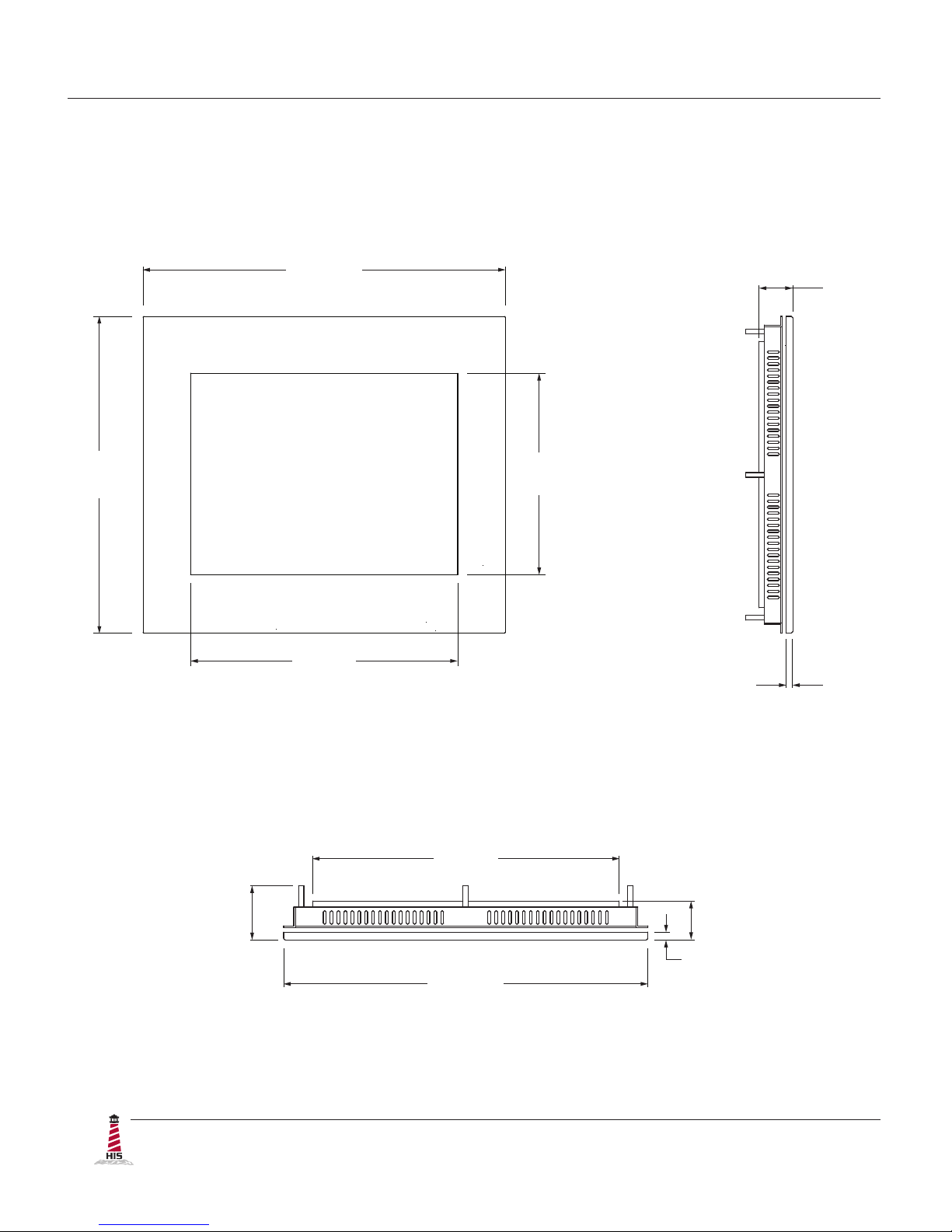
Front and Side Views �������������������������������������������������������������������������������������������������������������� 4
Bottom View ���������������������������������������������������������������������������������������������������������������������������� 4
Installation Instructions ��������������������������������������������������������������������������������������������������5
Step 1: Prepare for Installation ����������������������������������������������������������������������������������������������5
Step 2: Bench-test Conguration ������������������������������������������������������������������������������������������� 6
Install Cable Connections ������������������������������������������������������������������������������������������������������������������ 6
Install Touch Screen Driver ���������������������������������������������������������������������������������������������������������������� 7
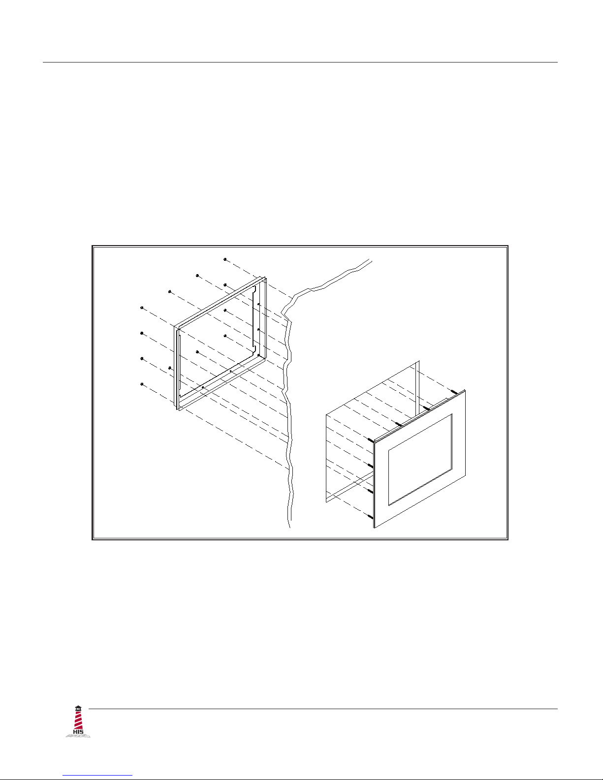
Step 3: Install into Panel �������������������������������������������������������������������������������������������������������� 9
Video Settings ���������������������������������������������������������������������������������������������������������������� 11
Setting the Timing Mode ������������������������������������������������������������������������������������������������������� 11
Control Panel Buttons �����������������������������������������������������������������������������������������������������������12
On-Screen Display (OSD) Menus ����������������������������������������������������������������������������������������� 14
Cleaning Instructions ����������������������������������������������������������������������������������������������������16
Troubleshooting ������������������������������������������������������������������������������������������������������������17
Video Troubleshooting ���������������������������������������������������������������������������������������������������������� 17
Touch Screen Troubleshooting ��������������������������������������������������������������������������������������������� 19
Specications ����������������������������������������������������������������������������������������������������������������20
Display ���������������������������������������������������������������������������������������������������������������������������������� 20
Video ������������������������������������������������������������������������������������������������������������������������������������� 20
Electrical �������������������������������������������������������������������������������������������������������������������������������21
Environmental �����������������������������������������������������������������������������������������������������������������������21
Functional �����������������������������������������������������������������������������������������������������������������������������21
Physical ��������������������������������������������������������������������������������������������������������������������������������22
Compliances and Certications �������������������������������������������������������������������������������������������� 22
Warranty Statement �������������������������������������������������������������������������������������������������������23

Safety and Regulatory Information
ML12D User Manual, January 2015 3
To prevent re or shock hazard, do not expose live components to rain or moisture�
Dangerously high voltages are present inside the unit� Do not disassemble the unit�
Refer servicing to qualied personnel only�
This equipment is not intended for use in critical applications where its failure
to operate would create immediate life threatening circumstances� Applications
including, but not limited to, nuclear reactor control, aerospace navigation systems
and life support systems are not appropriate for this product�
This product is intended to be mounted in a suitable cabinet or other enclosure�
The NEMA 4, 4X, or 12 ratings are applicable only when properly installed in a like
rated enclosure�
FCC Notice
This equipment has been tested and found to comply with the limits for a Class A digital
device, pursuant to Part 15 of the FCC Rules� These limits are designed to provide
reasonable protection against harmful interference when the equipment is operated
in a commercial environment� This equipment generates, uses, and can radiate radio
frequency energy and, if not installed and used in accordance with the instruction manual,
may cause harmful interference to radio communications� Operation of this equipment
in a residential area is likely to cause harmful interference in which case the user will be
required to correct the interference at his own expense� Any changes or modications not
expressly approved by the grantee of this device could void the user’s authority to operate
the device�
Safety and Regulatory Information
WARNING!
!
Waste Electrical and Electronic Equipment Directive (WEEE)
The following information is only for EU-member states:
The mark shown to the right is in compliance with the Waste Electrical and
Electronic Equipment Directive 2002/96/EC (WEEE)�
The mark indicates the requirement NOT to dispose of the equipment as unsorted
municipal waste, but use the return and collection systems according to local law� Users
should contact their supplier and check the terms and conditions of the purchase contract�
When purchased directly from Hope Industrial Systems, you may contact technical support
for disposal arrangements�

Mechanical Drawings
4 ML12D User Manual, January 2015
Mechanical Drawings
Front and Side Views
Bottom View
35.7 mm
(1.40")
7.1 mm
(0.28")
295.7 mm
(11.64")
338.1 mm
(13.31")
249 mm
(9.8")
188 mm
(7.4")
49.8 mm
(1.96")
280.9 mm
(11.06")
338.1 mm
(13.31")
35.7 mm
(1.40")
7.1 mm
(0.28")

Installation Instructions
ML12D User Manual, January 2015 5
Installation Instructions
Step 1: Prepare for Installation
IMPORTANT!
Perform the following steps BEFORE installation of the monitor into the panel�
1� Ensure that sufcient power is available�
2� Ensure that sufcient space is available to allow for proper air ow into and out of the
unit�
3� Ensure that the air temperature around the unit (top and bottom) will not exceed the
rated specications of the unit.
fThe maximum rated temperature for the HIS-ML12 is 50°C (122°F)�
fRemember that heat rises – the temperature at the top of the
cabinet will be much hotter than at the bottom if air inside the
enclosure is not actively circulating� Even in a sealed enclosure,
use of a circulation fan can greatly reduce temperature�
fAlso, remember that even though this product is designed to
operate at 50°C, the life span of any electronic device is shortened
when it is consistently operated at high temperatures� Therefore,
it is wise to take steps to keep the temperature of the ambient air
around the unit as low as possible�
4� Ensure that the ambient humidity of the air around the unit does not exceed the
specications of the unit.
fThe maximum rated humidity for the HIS-ML12 is 90%
non-condensing�
!

Installation Instructions
6 ML12D User Manual, January 2015
Step 2: Bench-test Conguration
Make sure everything works before installing into the production environment�
TIP!
If using a KVM extender, please refer to the installation instructions included
with the KVM extender module� It is particularly important to bench-test the full
conguration prior to nal installation� This will help to identify and troubleshoot
any system issues while conguration changes may still be easily made�
Install Cable Connections
All monitors are shipped with a 6 ft� (1�8 m) VGA video cable, 6 ft� (1�8 m) power cable, and
power supply, unless longer cables were ordered in their place� If you ordered a touch screen
monitor, you also received a 6 ft� (1�8 m) USB cable, unless a longer cable was ordered in its
place� Serial (RS-232) cables may be ordered separately�
The cable ports are located on the rear of the monitor� Refer to the following diagram and
instructions to connect power, video, and touch screen (if applicable) to your monitor�
VIDEO
USB
(for Touch Screen
option)
SERIAL
(RS-232)
POWER INPUT
CONTROL PANEL BUTTONS

Installation Instructions
ML12D User Manual, January 2015 7
Video Connection
The HIS-ML12 supports analog video� Connect one end of the VGA video cable to the HD-15
input port on the rear of the monitor� Connect the other end to the video output port on the host
computer�
Power Connection
The HIS-ML12 is powered by 12 VDC, 2�5 A (100 to 240 VAC, 60/50 Hz with external power
adapter)�
Connect the external power adapter barrel connector to the DC power input on the rear of the
monitor� Connect the supplied AC power cable to the external power adapter and to a nearby
outlet� Secure the external power adapter to the rear of the monitor using the supplied bracket�
Install Touch Screen Driver
Applies to touch screen monitors only� Instructions below apply to Windows systems� Both Serial
and USB ports are present on all touch screen monitors, but only one should be used to connect
the touch screen interface to the monitor�
All touch screen monitors are shipped with a CD-ROM that contains documentation and drivers
for all major operating systems� To be sure that you have the most current information, please
check the following Internet address:
http://www�HopeIndustrial�com/Touchscreen_Drivers�htm
IMPORTANT!
If you will be using a USB connection, install the touch screen driver rst, and then
connect the USB cable� If you will be using a Serial connection, connect the Serial
cable rst, and then install the touch screen driver�
USB Connection
1� Select the appropriate driver for your operating system�
a� If downloading from the web address listed above, select the appropriate
driver for your operating system�
b� If using the included CD, insert it into the host computer's CD-ROM drive�

Installation Instructions
8 ML12D User Manual, January 2015
If the CD does not automatically run, browse the contents of the CD and
open the READ�ME�FIRST�htm le in a web browser� Select the appropriate
driver�
2� Click to "Run" the software when prompted� Follow on-screen instructions to
download and execute the touch screen driver installation�
3� A cable retention clip comes installed on the USB port on the rear of the monitor and
will help to secure the cable and ensure adequate strain relief� Without removing the
clip, route one end of the USB cable through the retention clip and connect it to the
USB input port on the monitor� Connect the other end to the USB port on the host
computer�
Serial (RS-232) Connection
1� Connect one end of the Serial cable to the Serial input port on the rear of the monitor�
Connect the other end to the Serial port on the host computer� Tighten the captive
screws on the cable connectors to ensure adequate strain relief�
2� Select the appropriate driver for your operating system�
a� If downloading from the web address listed above, select the appropriate
driver for your operating system�
b� If using the included CD, insert it into the host computer's CD-ROM drive�
If the CD does not automatically run, browse the contents of the CD and
open the READ�ME�FIRST�htm le in a web browser� Select the appropriate
driver�
3� Click to "Run" the software when prompted� Follow on-screen instructions to
download and execute the touch screen driver installation�
Calibrate the Touch Screen
Once the driver has nished installing, you are ready to calibrate the touch screen�
Open the touch screen's Control Panel by clicking on the "Elo Touchscreen" icon,
located in the host computer's Control Panel� Under the "General" tab, click the
"Align" button to start the calibration routine�

Installation Instructions
ML12D User Manual, January 2015 9
1� Refer to the drawing below for the cutout dimensions for the HIS-ML12�
2�
263 mm
(10.35")
308 mm
(12.12")
Locate position in panel for mounting of the monitor� Ensure that there is adequate
space behind the panel� Allow extra space – 12�7 mm (0�5") behind and on each
side – for air ventilation�
Step 3: Install into Panel
Once you have completed the full bench-test conguration and conrmed that all components are
working properly, you are ready to install the monitor into its panel cutout�
WARNING!
Hope Industrial Systems will not assume liability for damage to internal electronics
due to improper installation� Contact Hope Industrial Systems if you need additional
assistance�
!

Installation Instructions
10 ML12D User Manual, January 2015
3� Cut a rectangular hole in the panel�
fCutout Dimensions (W x H) for the HIS-ML12:
308 mm x 263 mm (12�12" x 10�35"); ± 0�5 mm (0�020")
4� Clean and deburr the panel hole�
5� Separate the rear collar from the monitor by removing the 8 nuts�
6� Refer to the enclosure mounting diagram below�
7� Insert the unit into the front of the panel and re-attach the collar�
NOTE: Contact Hope Industrial Systems if for any reason your application does
not allow for installation of the collar�
8� Tighten all 8 nuts to a torque of 10-15 inch-pounds to ensure a watertight seal
between the bezel gasket on the monitor and the equipment panel� Go around all
nuts twice to ensure an even compression on gasket�
NOTE: If a torque wrench is not available, tighten all nuts evenly until bezel sits
1�6 to 2�4 mm (1/16" to 3/32") off the front of the panel�
Table of contents
Other HIS Industrial Monitor manuals
Popular Industrial Monitor manuals by other brands

Austin Hughes
Austin Hughes RP-F821 user manual

WAGO
WAGO WAGO-PERSPECTO 762 Series Operating and assembly instructions

Advantech
Advantech IDS-3319 Series user manual

Acnodes
Acnodes APH 8064 user manual

Acnodes
Acnodes APW 5400 user manual

Dynamic Displays
Dynamic Displays QES1500 Progressive Series user manual

AXIOMTEK
AXIOMTEK Dk3g4PANEL 6153-O/P user manual

ESA
ESA XM7W7 installation manual

Siemens
Siemens SIMATIC Industrial Flat Panel IFP2200 Product information

Siemens
Siemens INOX PRO SIMATIC IFP1900 Compact operating instructions

Advantech
Advantech IDK-1115WP-45FHA1 user manual

Eaton
Eaton XV-152 Series operating instructions


