manuals.online logo
Brands
  1. Home
  2. •
  3. Brands
  4. •
  5. ACU-RITE
  6. •
  7. Measuring Instrument
  8. •
  9. ACU-RITE SENC 50 User manual

ACU-RITE SENC 50 User manual

This manual suits for next models

4

Other ACU-RITE Measuring Instrument manuals

ACU-RITE MILLPWRG2 User manual

ACU-RITE

ACU-RITE MILLPWRG2 User manual

ACU-RITE 200S READOUTS User manual

ACU-RITE

ACU-RITE 200S READOUTS User manual

ACU-RITE smartHUB User manual

ACU-RITE

ACU-RITE smartHUB User manual

ACU-RITE VRO 300T User manual

ACU-RITE

ACU-RITE VRO 300T User manual

ACU-RITE 01083 User manual

ACU-RITE

ACU-RITE 01083 User manual

ACU-RITE 01083 User manual

ACU-RITE

ACU-RITE 01083 User manual

ACU-RITE 06034 User manual

ACU-RITE

ACU-RITE 06034 User manual

ACU-RITE 06008RM User manual

ACU-RITE

ACU-RITE 06008RM User manual

ACU-RITE ENC 125 T User manual

ACU-RITE

ACU-RITE ENC 125 T User manual

ACU-RITE 00795 User manual

ACU-RITE

ACU-RITE 00795 User manual

ACU-RITE DRO10X User manual

ACU-RITE

ACU-RITE DRO10X User manual

ACU-RITE 01410 User manual

ACU-RITE

ACU-RITE 01410 User manual

ACU-RITE 00325CADI User manual

ACU-RITE

ACU-RITE 00325CADI User manual

ACU-RITE 00256 User manual

ACU-RITE

ACU-RITE 00256 User manual

ACU-RITE 325 User manual

ACU-RITE

ACU-RITE 325 User manual

ACU-RITE 00276RM User manual

ACU-RITE

ACU-RITE 00276RM User manual

Popular Measuring Instrument manuals by other brands

Powerfix Profi 278296 Operation and safety notes

Powerfix Profi

Powerfix Profi 278296 Operation and safety notes

Test Equipment Depot GVT-427B user manual

Test Equipment Depot

Test Equipment Depot GVT-427B user manual

Fieldpiece ACH Operator's manual

Fieldpiece

Fieldpiece ACH Operator's manual

FLYSURFER VIRON3 user manual

FLYSURFER

FLYSURFER VIRON3 user manual

GMW TG uni 1 operating manual

GMW

GMW TG uni 1 operating manual

Downeaster Wind & Weather Medallion Series instruction manual

Downeaster

Downeaster Wind & Weather Medallion Series instruction manual

Hanna Instruments HI96725C instruction manual

Hanna Instruments

Hanna Instruments HI96725C instruction manual

Nokeval KMR260 quick guide

Nokeval

Nokeval KMR260 quick guide

HOKUYO AUTOMATIC UBG-05LN instruction manual

HOKUYO AUTOMATIC

HOKUYO AUTOMATIC UBG-05LN instruction manual

Fluke 96000 Series Operator's manual

Fluke

Fluke 96000 Series Operator's manual

Test Products International SP565 user manual

Test Products International

Test Products International SP565 user manual

General Sleep Zmachine Insight+ DT-200 Service manual

General Sleep

General Sleep Zmachine Insight+ DT-200 Service manual

Sensa Core Lacto Spark user manual

Sensa Core

Sensa Core Lacto Spark user manual

VOLTCRAFT UTS-1980 operating instructions

VOLTCRAFT

VOLTCRAFT UTS-1980 operating instructions

EBCHQ 94915 Operation manual

EBCHQ

EBCHQ 94915 Operation manual

Balluff BIP LD2-T017-01-EP-S4 Series user guide

Balluff

Balluff BIP LD2-T017-01-EP-S4 Series user guide

Pulsar IMP Lite Series instruction manual

Pulsar

Pulsar IMP Lite Series instruction manual

ETCR 6800 user manual

ETCR

ETCR 6800 user manual

manuals.online logo
manuals.online logoBrands
  • About & Mission
  • Contact us
  • Privacy Policy
  • Terms and Conditions

Copyright 2025 Manuals.Online. All Rights Reserved.

1
Digital Readouts
Linear Encoders
For Manually-Operated
Machine Tools
04/2019
2
Digital readouts from ACU-RITE make your
manually operated machine tools more
protable, improve productivity and raise the
quality of the machined workpiece.The 7"
TFT color at panel display shows the actual
axis position lucidly and clearly. The context-
sensitive graphical user guidance makes
working with digital readouts from ACU-RITE
a pleasure.
Together with the linear scales from
ACU-RITE they form an economic and
effective package solution for initial setup or
retrotting on your machine tool.
3
Contents
Digital readouts
Selection guide 4
Functions Installation guide (DRO203, DRO300) 6
Probing functions for presets (DRO300) 6
Tool compensations (DRO203, DRO300) 6
Distance-to-go display (DRO100, DRO203, DRO300) 7
Dynamic zoom (DRO203, DRO300) 7
Hole patterns (DRO203, DRO300) 8
Programming of machining steps (DRO300) 8
Assistance for working with lathes (DRO203, DRO300, DRO303) 9
Specications DRO100 – Simple digital readout for one, two, or three axes 10
DRO203 – Versatile digital readout for up to three axes 12
DRO300 – Programmable digital readout for three or four axes 14
Accessories Edge nder 16
Mounting components 17
IOB 610 external input/output unit for DRO300 19
Interfaces 21
Linear encoders
Linear encoders – For manually-operated machine tools 22
Mounting instructions 23
Specications SENC 50 – Compact linear encoder for limited installation space 24
SENC 150 – Standard linear encoder 26
Interfaces Incremental signals « TTL 28
Electrical connection Cable 29
General electrical information 30
4
Selection guide
Number of axes Reference points/
Tool data
Functions Encoder
inputs
Switching inputs/
outputs
Data
interface
Models Page
DRO100
Digital readout for general applications
with up to three axes
• 7” TFT color display
• Splash-proof membrane keyboard
1, 2 or 3 1 datum General:
• Absolute/incremental display
• mm/inch switching
Turning:
• Radius/diameter display
« TTL –USB
Type C
DRO101,
DRO102,
DRO103
10
DRO203
Digital readout for milling, drilling and
boring machines, as well as for lathes with
three axes
• 7” TFT color display
• Splash-proof full-travel keyboard
Up to 3 10 datums
16 tools
General:
• Distance-to-go display with graphic positioning
aid
Milling and drilling:
• Probing function using tool
• Tool radius compensation
• Hole patterns (circular and linear patterns)
Turning:
• Radius/diameter display
• Separate/sum display
« TTL –USB
Type C
DRO203 12
DRO300
Digital readout for milling, drilling and
boring machines, as well as for lathes with
up to three axes
• 7” TFT color display
• Program memory
• Splash-proof full-travel keyboard
• Switching inputs/outputs (via IOB 610)
Up to 4 10 datums
99 tools
General:
• Distance-to-go display with graphic positioning
aid
• Program memory for up to 8 programs with 250
steps each
Milling and drilling:
• Probing functions for KT edge nder
• Tool radius compensation
• Hole patterns (circular and linear patterns)
Turning:
• Taper calculator
• Radius/diameter display
• Separate/sum display
« TTL For KT edge nder;
additional ones via
IOB 610
USB
Type C
DRO303,
DRO304 14
5
Number of axes Reference points/
Tool data
Functions Encoder
inputs
Switching inputs/
outputs
Data
interface
Models Page
DRO100
Digital readout for general applications
with up to three axes
• 7” TFT color display
• Splash-proof membrane keyboard
1, 2 or 3 1 datum General:
• Absolute/incremental display
• mm/inch switching
Turning:
• Radius/diameter display
« TTL –USB
Type C
DRO101,
DRO102,
DRO103
10
DRO203
Digital readout for milling, drilling and
boring machines, as well as for lathes with
three axes
• 7” TFT color display
• Splash-proof full-travel keyboard
Up to 3 10 datums
16 tools
General:
• Distance-to-go display with graphic positioning
aid
Milling and drilling:
• Probing function using tool
• Tool radius compensation
• Hole patterns (circular and linear patterns)
Turning:
• Radius/diameter display
• Separate/sum display
« TTL –USB
Type C
DRO203 12
DRO300
Digital readout for milling, drilling and
boring machines, as well as for lathes with
up to three axes
• 7” TFT color display
• Program memory
• Splash-proof full-travel keyboard
• Switching inputs/outputs (via IOB 610)
Up to 4 10 datums
99 tools
General:
• Distance-to-go display with graphic positioning
aid
• Program memory for up to 8 programs with 250
steps each
Milling and drilling:
• Probing functions for KT edge nder
• Tool radius compensation
• Hole patterns (circular and linear patterns)
Turning:
• Taper calculator
• Radius/diameter display
• Separate/sum display
« TTL For KT edge nder;
additional ones via
IOB 610
USB
Type C
DRO303,
DRO304 14
6
Functions
– Installation guide (DRO203, DRO300)
– Probing functions for presets (DRO300)
– Tool compensations (DRO203, DRO300)
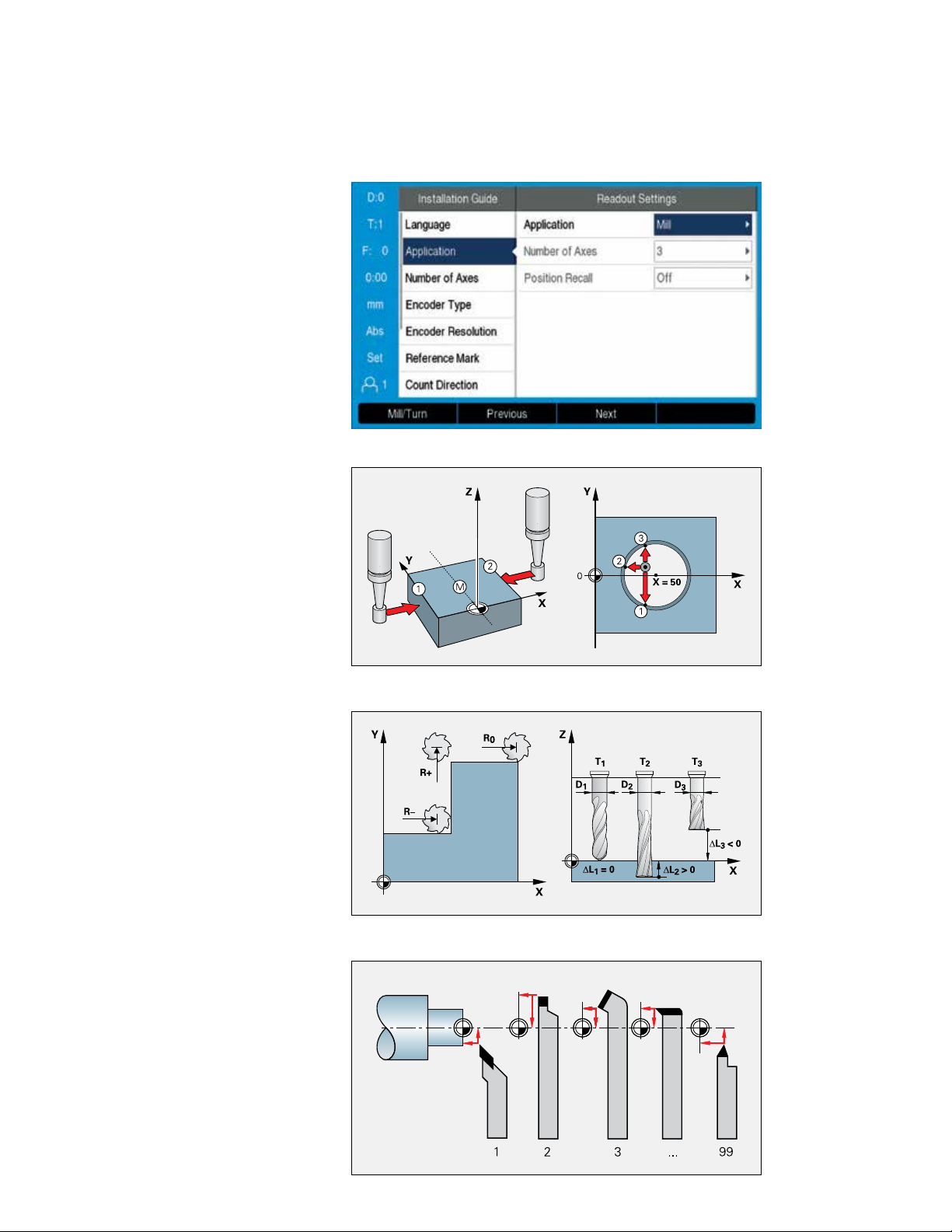
Installation guide
At rst switch-on, an installation guide will
guide you step by step through the congu-
ration of the unit. During this procedure, you
can select the connected encoder directly
from a list and thereby adopt all of the encoder
parameters. It only takes a few moments to
congure the basic functions of the digital
readout.
You can then separately congure further
settings such as scaling factor, error
compensation, etc.
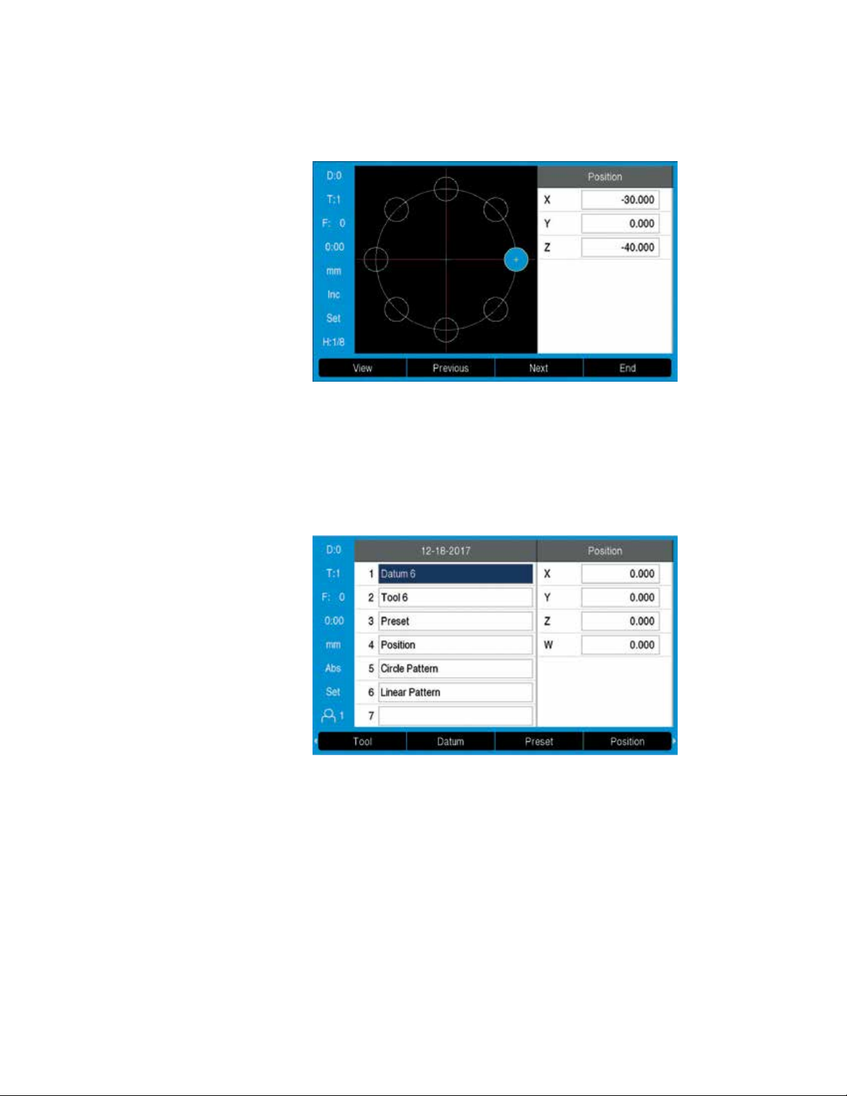
Easy setup with probing functions
A very useful accessory for datum setting is
the HEIDENHAIN KT edge nder: simply
move the edge nder toward a side of the
workpiece until the stylus deects. The
digital readout stores the exact position on
its own and automatically takes into account
the direction of approach and the radius of
the stylus or the tool. For this purpose, the
digital readout provides the following probing
functions:
• Workpiece edge as reference line
• Workpiece centerline as reference line
• Circle center as datum
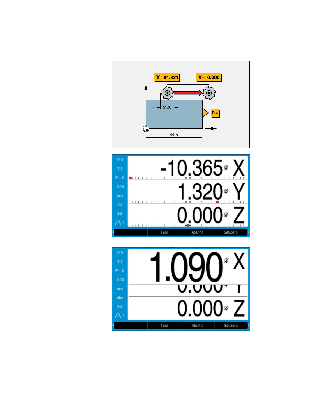
Tool compensation for milling machines
The ACU-RITE digital readouts save tool data
in a tool table (i.e., diameter and length of the
tool used). The data can come from preset
tools or be measured on the machine.
When positioning in distance-to-go mode, the
readouts take the tool radius (R+ or R–) in
the machining plane into account and con-
sider the tool length (L) in the spindle axis.
Determining and storing tool
compensation values on lathes
You can store the data for the tools you insert
in the turret or quick-change holder in the
tool table:
• Enter the tool position directly when
turning the rst diameter, or
• “freeze” the current axis position value,
retract the tool, measure the turned
diameter and then enter that value.
Changing the datum
If you change the workpiece or a datum, then
you can set a new preset. The tool data are
then automatically referenced to the new
datum and do not need to be changed.
Compensation of tool radius and length
Convenient datum setting with an edge nder
7
– Distance-to-go display (DRO100, DRO203, DRO300)
– Dynamic zoom (DRO203, DRO300)
Distance-to-go display
for turning and milling
The distance-to-go display feature simplies
your work considerably: you enter the next
nominal position, and the display shows you
the distance remaining to the target position.
This means that you simply move to the
display value zero.
When you use the distance-to-go feature for
milling, the digital readout can compensate
for the milling radius. In this way you can
directly use the drawing dimensions without
having to do any conversions. You no longer
have to remember any complicated values.
Dynamic zoom
The dynamic zoom feature offers a signicant
improvement in position value readability.
Once activated, the display value for the axis
currently being moved is maximally enlarged.
This occurs in four steps depending on the
number of digits in the respective numerical
value. For small numbers (i.e., numbers close
to zero), the character height can be increased
from 17mm (standard height) to 25 mm. The
operator immediately sees which axis is
currently moving and can also easily read the
numerical value from a greater distance.
When the axis stops moving, the display
returns to its standard size after a second
has elapsed.
The distance-to-go display is enhanced by
a“near zero” message: as you traverse to
zero, a square cursor moves into a target
fork.The “near zero” message is
congurable for each axis.
8
Functions
– Hole patterns (DRO203, DRO300)
– Programming of machining steps (DRO300)
Automatic calculation of bolt hole
patterns for milling and drilling
In milling machine mode, you can machine
circular hole patterns (full circle or circle
segments) and linear hole patterns without
much calculation.
You simply enter the geometric dimensions
and the number of holes from the drawing.
The display calculates the coordinates of the
individual holes in the working plane.You
only need to traverse “to zero” and drill.The
display then shows the next position.The
graphic display is a particularly useful
feature: it lets you verify your input for the
programmed bolt-hole pattern before
machining.
Programming machining steps
The programming functions of the DRO300
allow you to save repetitive machining steps.
For example, you can save all of the
machining steps required for a small batch in
the form of a program. In the RUN mode of
operation, the distance-to-go display will
guide you step-by-step to the programmed
positions.
You create programs by typing in the
positions step by step.The xed cycles such
as Bolt Hole Circle, Linear Hole Pattern,
Incline Mill Form or Circular Arc keep your
programs short and save you programming
time. In the course of your work, the readout
presents each nominal position in the proper
sequence. You need only move from one
position to the next.
9
– Assistance for working with lathes (DRO203, DRO300, DRO303)
Radius/diameter display
In lathe mode, you can see the positions
ofthe transverse axis in either radius or
diameter values.You can switch at a
keystroke.
Sum display of longitudinal axes
In lathe mode, the positions of the saddle
and the top slide are displayed either
separately or as the sum of both values.
• If you select separate displays, the
position values are referenced to the
datum for each individual axis. If only the
saddle is moved, the displayed value for
the top-slide axis remains unchanged
• If sum display is selected, the counter
adds both values while taking the
algebraic sign into account. You can
thereby read the absolute position of the
tool in relation to the workpiece datum
without having to perform calculations.
•Vectoring (DRO203, DRO300)
The vectoring function breaks down a
movement into its longitudinal and
crossfeed axis components. If you are
turning threads, for example, vectoring lets
you see the diameter of the thread in the
X axis, even though you are moving the
compound axis handwheel
Taper turning made easy
(DRO203, DRO303)
If taper dimensions do not include the angle,
the integrated taper calculator will help you
with the calculation. Simply enter the taper
ratio or the two diameters and the length.
The correct angle for the top slide will be
displayed immediately.
Constant surface speed (DRO300)
Particularly in taper turning or parting, the
surface speed usually changes along with
the diameter. But a constant surface speed
is better for optimum machining results and
long tool life. In conjunction with the IOB 610
output module, the DRO 300 digital readout
therefore makes it possible to control a
constant surface speed contingent on the
current workpiece diameter.
10
285 46
50
160
ID
SN
1234567-xx
DRO 10x
12 345 678 x
www.acu-rite.com
19
27
35
54
89.6
100
228.9
10029.5
55.7
73
90.2
127
DRO100
– Simple digital readout for one, two, or three axes
The ACU-RITE DRO100 digital readouts are
well-suited for general applications on
milling, drilling, boring and lathe machines
with one, two, or three axes.
Design
With its sturdy housing and splash-proof
membrane keyboard, the DRO100 is built for
the workshop.The DRO100 displays position
values, status information, and additional
useful data on a TFT color screen.
Functions
The most important functions are available
quickly and directly via function keys. If the
DRO100 is connected to a lathe, then you
can simply switch from radius to diameter
display. For lathes with a separate top slide,
the sum display feature on the 3-axis
version of the DRO100 allows you to display
the saddle and top slides either together or
separately.
Data Interfaces
A USB port enables the writing and reading
out of data and les.