The ENC 150 precision glass scale linear encoder provides the
accuracy and reliability of an ACU-RITE measuring system with
digital output (analog output available). Features and options
include:
Digital resolutions of 1, 2, 5, or 10 µm.
Accuracy grades of ±3, and ± 5 µm / 1000mm.
Home reference signal (Ref. Mark) coded or 200mm interval.
Vinyl or Armor cables of 5, 10, and 15 ft. length.
Mounting fasteners, center supports, and backup spars.
Installation brackets and accessories.
Contact your Authorized ACU-RITE Distributor for assistance with
selection of product options and accessories.
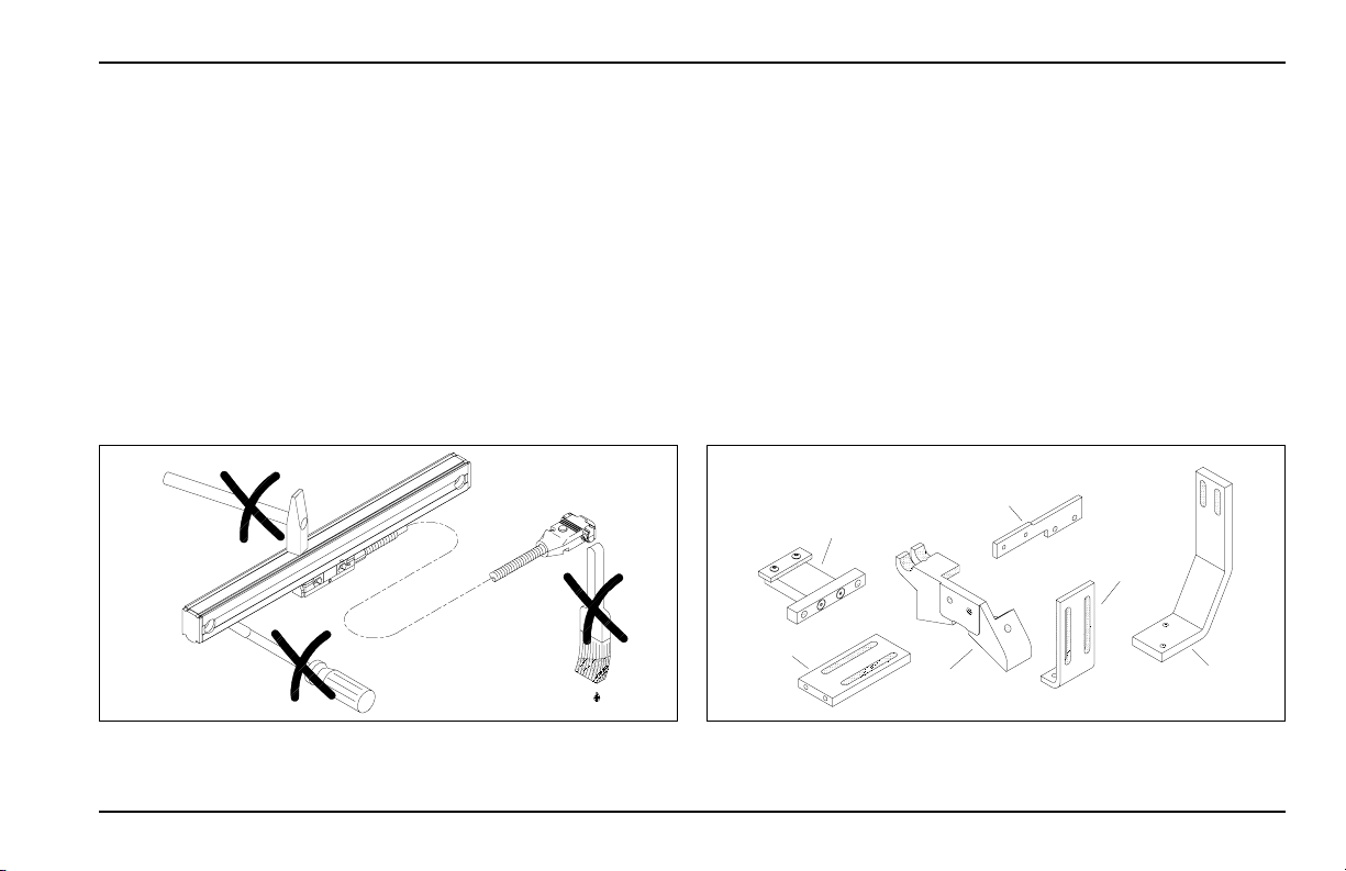
A) ENC 150 Linear Encoder
B) Backup Spar
C) Linear Encoder Reference Manual
D) Cable Mounting Hardware
E) Linear Encoder Mounting Hardware
F) Backup Spar Mounting Hardware
ACU-RITE ® 2
Introduction ENC 150
C
A
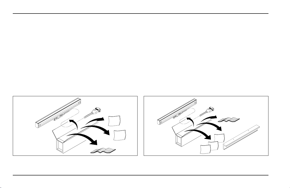
Shipping carton
contents
D
E
ENC 150
2 thru 60
B
C
A
E
D
F
Shipping carton
contents
ENC 150
65 and over
For future ordering information or warranty service, record the linear
encoder catalog number located on the scale assembly tag, and
the serial number from the reading head tag.
Catalog No. Serial No.
Axis # 1: _______________ __________________
Axis # 2: _______________ __________________
Axis # 3: _______________ __________________
Axis # 4: _______________ __________________
Date of purchase: _______________ __________________
Distributor: _______________ __________________
Address: _______________ __________________
Telephone: _______________