Installation Manual 385072-41
P.N. 385072-214 Ed C 11/05 3Acu-Rite Companies Inc.
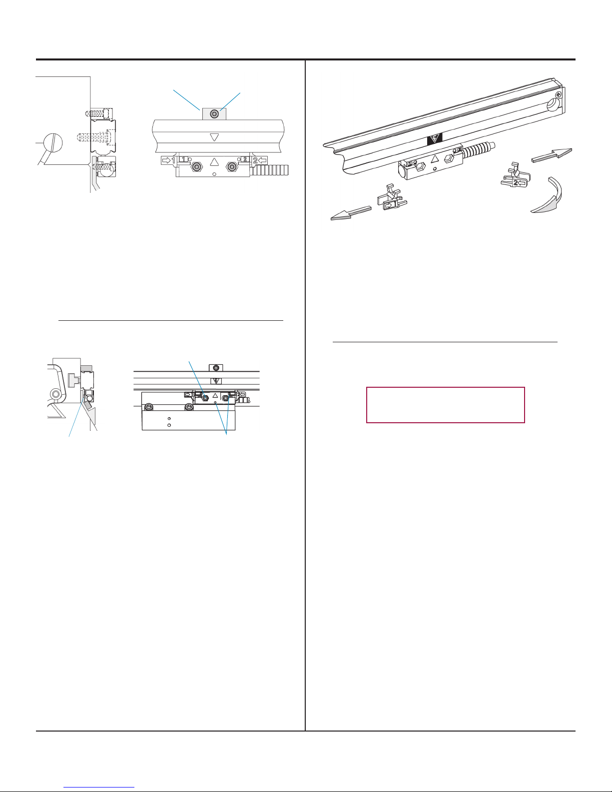
Alignment bracket removal ...
•Useallen wrench from set screw adjustment to slide
alignmentbracketsawayfromthereading head.
•Removealignmentbracketsandsaveforpossible
futureuse.
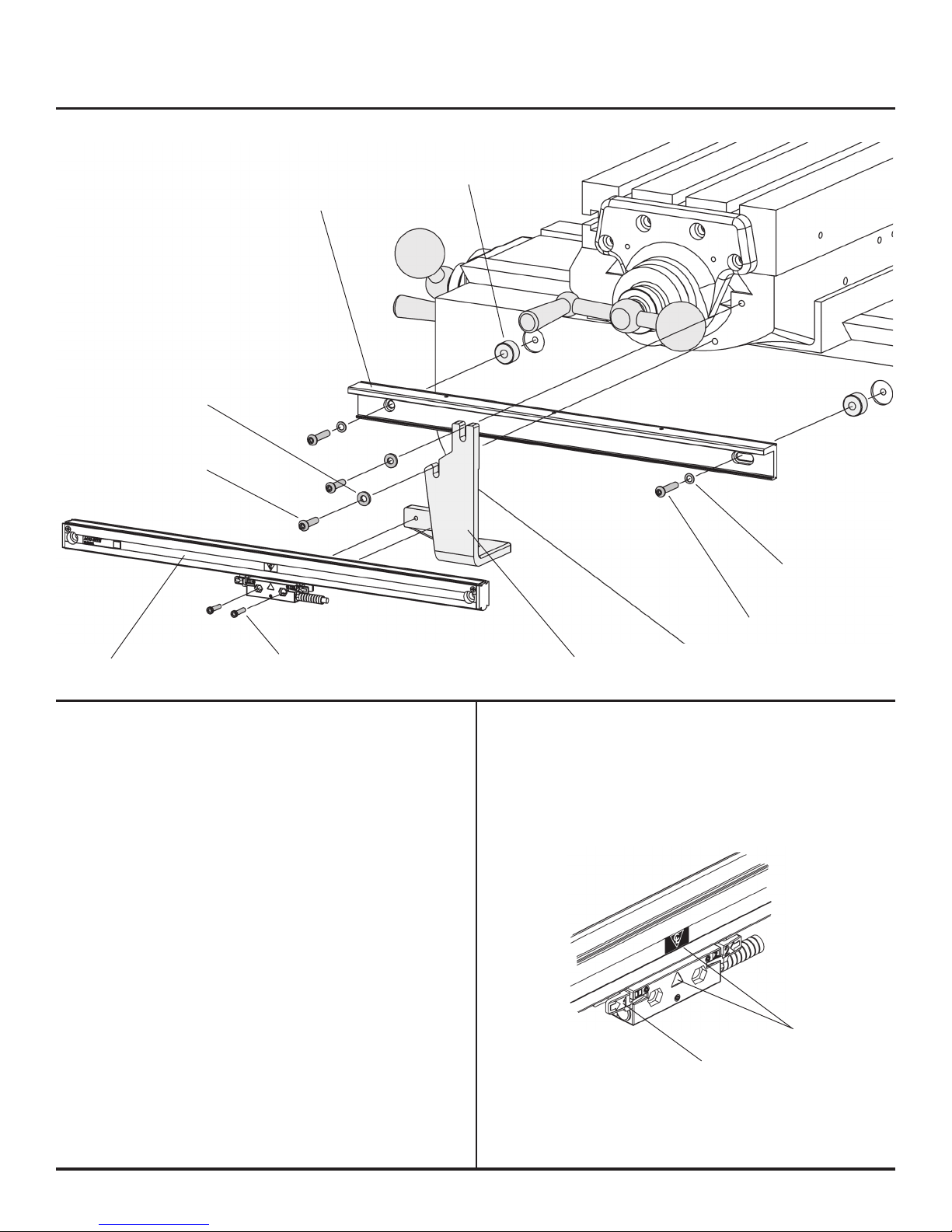
•Move the axis through its full travel. Confirm that
theassemblydoesnotinterferewiththemachine
movement.
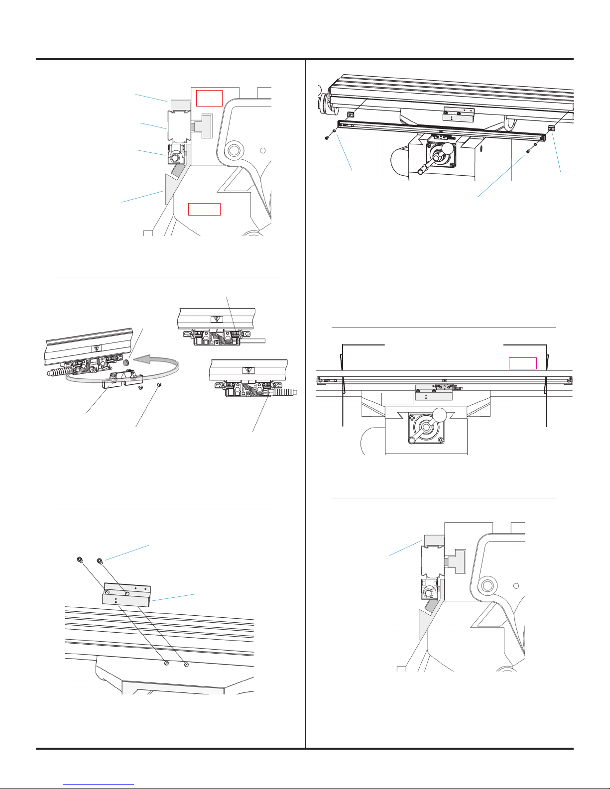
Slide brackets back
away from the
reading head and
cable Twist brackets
45° to remove
Leveling set screws (3)
*8-32 x 3/4” SHCS (2)
•Adjustthebracket so that the reading head
mountingholesalignwith the reading head casting.
Securethe bracket in place.
Reading head
mounting holes (2)
A gap will exist between
bracket and reading head.
•Insert the two *8-32 x 5/8” SHCS. Insure the bracket
isadjustedtoprovideproperscrewheadclearance.
Do Not Tighten Screws at this time.
•Set each leveling set screw by placing a .001” - .003”
feelergagebetweenthesetscrewandthebracket.
•Adjust each set screw until a slight drag is felt on the
feelergage.
• Evenly tighten the two 8-32 SHCS.
•Withthelongitudinalaxisinstallationcomplete,
routethecablesprovidingsufficientslackloopsfor
machinemovementtothereadout.
•Securecables by fastening with clips or ties.
•Attachthelinearencoderconnectorstothereadout.
•Completetheinstallationbyfollowingthestepsin
“CheckingYourInstallation”sectionintheencoder
“ReferenceManual”.
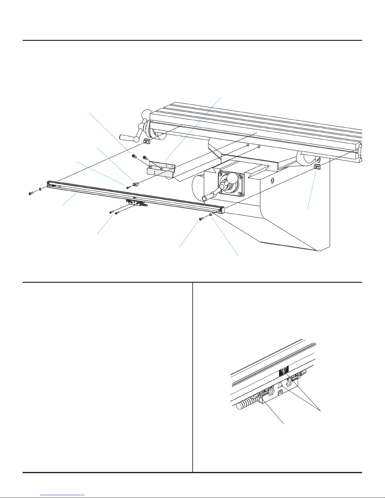
Encoder Installation Manual For: Bpt. Vert. Knee Milll
Cross Feed Y Axis - Right hand side
SENC 150
Reading head installation...