ACU-RITE ENC 150 User manual

ENC 150™
ACU-RITE
®
REFERENCE MANUAL

Page
Introduction .............................................................................. 2
Mounting Preparation............................................................... 3
Mounting Information ............................................................... 4
Encoder Dimensions................................................................ 5
Backup Spar Dimensions ........................................................ 6
Mounting Requirements........................................................... 7
Typical Mounting (s)................................................................. 8
Encoder Installation Procedure ............................................... 9
Page
Spar Installation Procedure ..................................................... 11
Checking your Installation........................................................13
Electrical Shielding ................................................................ 14
Troubleshooting ..................................................................... 15
Mechanical Specifications ..................................................... 16
Output Signals and Pin-Outs ................................................. 17
Electrical Specifications ......................................................... 18
The ACU-RITE Warranty ....................................................... 19
•Installation brackets and kits are available.
• Your Authorized ACU-RITE Distributor can assist you with your
selection of these for your installation.
1ACU-RITE
®
Motor mount
Reading Head
bracket
Horizontal mt.
bracket
Extension
bracket
Side mount
bracket
Rear mount
bracket
ENC150 Table of Contents

B
C
A
E
D
F
The ENC 150 precision glass scale linear encoder provides the
accuracy and reliability of an ACU-RITE measuring system with
digital output (analog output available). Features and options
include:
•Resolutions of .5, 1, 2, 5, or 10 µm.
•Accuracy grades of
±
3, and ± 5 µm / 1000 mm.
• Vinyl or Armor cables of 2, 5, 10, 15 and 20 ft. length.
•Fasteners, center supports, and backup spars.
•Brackets and accessories.
Contact your Authorized ACU-RITE Distributor for assistance with
the selection of product options and accessories.
A) ENC 150 Linear Encoder
B) Backup Spar
C) Reference Manual
D) Cable Mounting Hardware
E) Linear Encoder Mounting Hardware
F) Backup Spar Mounting Hardware
ACU-RITE
® 2
Introduction ENC 150
C
A
Contents
< 60”
D
E
Contents
> 65”
Forfuture ordering information or warranty service,recordthelinear
encoder catalog number located on the scale assembly tag, and
the serial number from the reading head tag.
Catalog No. Serial No.
Axis # 1: _______________ __________________
Axis # 2: _______________ __________________
Axis # 3: _______________ __________________
Axis # 4: _______________ __________________
Date of purchase: _______________ __________________
Distributor: ____________________________________
Address: ____________________________________
Telephone: ____________________________________

Please follow these preparation guide lines.
•Understand your mounting requirements.
•Mount with lip seals down and away from the work area.
•Brackets should be kept as short as possible and rigid.
•Surfaces must be in good condition, clean, and free of dirt.
Remove paint from machined mounting surfaces.
•Alignment brackets must not be removed until instructed.
•Machine travel can not exceed the encoder measuring length.
•Either limit machine travel or obtain correct length scale.
•Determine cable exit direction before installing.
• To change cable exit direction; remove base and rotate 180°.
•Never mount with lip seals upward or towards work area.
3ACU-RITE
®
ENC150 Mounting Preparation
“L” = Measuring length
+ 1.75” nominal
over travel
“L”
1.150
1.150
Cable direction
Rotate reading head
base 180°

Use this information to plan your Linear Encoder installation.
•Mountthe linear encoders close to machineguidewaystoensure
system accuracy.
•Onesideofthelinearencoderaddressesflushmountingsurfaces,
and the opposite side addresses offset mounting surfaces.
•If space between the reading head and the mounting surface
exceeds .18”, use a spacer or mounting bracket to reduce space.
•ACU-RITEbracketkitinstructionsprovide step by step installation
proceedures.
• Tolerances of .010” TIR apply to all mounting dimensions.
•Center support mounting surface required for 24” through 60”
linear encoder measuring lengths mounted without a spar.
•Allow clearance for alignment bracket removal.
•Alignment brackets must not be removed until instructed. •Usereadingheadlevelingsetscrewswhensurfacesarenot flush.
•Reading head bracket required for a space >.18”.
ACU-RITE
® 4
Mounting Information ENC150
Scale case
Flush
mounting Offset
mounting Backup spar
mounting
-A- = Machine Travel
Reading head
B
Equal Equal
1.826 ±.010 [46.5]
// .010 A
// .010 A
// .010 B
// .010 A
// .010 A
0.0 ± .010
Move bracket past
the cable strain relief
Alignment bracket removal clearance
1.0
[25mm] 1.38
[35mm]
Alignment
bracket
Alignment
bracket

5ACU-RITE
®
ENC150 Encoder Dimensions
Measuring length + 6.375
Measuring length + 5.437
.469
[11.9]
.944
[24.0]
.320
[8.1]
∅ .500 C’Bore
∅ .313 Thru
Reading Head
assembly 2.250
[57.1]
1.125
[28.6]
.56
[14.4]
.100
[2.5]
∅ For 8-32
(or M4) SHCS
mounting
screw
.32
[8.4]
Armor
.20
[5.2]
Vinyl
1.25 [32]
Min. bend rad.
Max. nominal linear encoder over travel 1.825
Published over travel 1.75”
.810
[20.6]
.285 [7.2]
1.826
[46.4]
1.12
[28.5]
End Cap
Mounting hole
Scale case .562
[14.3]
.570
[14.5]
.810
[20.5] 1.060
[27.0]
2.148
Ref.
[54.6]
.250
[3.4] .660
[16.8]
1.440
[36.6]
.750
[19.0]
.121
[3.11]
With Backup
Spar
.937
[23.8]
.700
[17.8]
.750
[19.0]

ACU-RITE
® 6
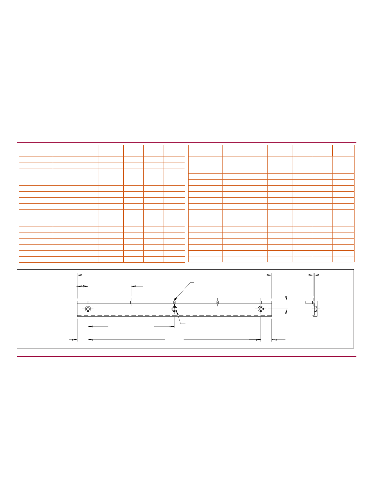
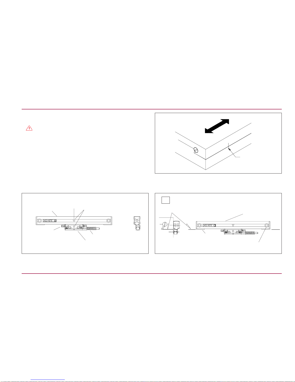
Backup Spar Dimensions ENC 150
“A” ± .015
“A” ± .005
“L” ± .015
5.000 typ. ± .015
Non
Accumulative
“B” typ. ± .015
Non Accumulative “A” Ref.
.750 ± .005
.110 ± .005
M4 Thru
∅.312 Thru
∅.500 C’Bore x .160 Dp.
“X” No. of holes
“E”
Backup spar
Part Number Linear Encoder
Measuring Length LA
X No.
Places B
385102-000 2 8.312 1.656 2 5.000
385104-000 4 10.312 2.656 2 5.000
385106-000 6 12.312 1.156 2 10.000
385108-000 8 14.312 2.156 2 10.000
385110-000 10 16.312 3.156 2 10.000
385112-000 12 18.312 4.156 2 10.000
385113-000 13 (Special) 19.312 1.44 2 16.43
385114-000 14 20.312 5.156 2 10.000
385116-000 16 22.312 1.156 3 10.000
385118-000 18 24.312 2.156 3 10.000
385120-000 20 26.312 3.156 3 10.000
385122-000 22 28.312 4.156 3 10.000
385124-000 24 30.312 5.156 3 10.000
385126-000 26 32.312 1.156 4 10.000
385128-000 28 34.312 2.156 4 10.000
385130-000 30 36.312 3.156 4 10.000
385131-000 31.5 38.030 4.015 4 10.000
385132-000 32 (“E” 34.812) 35.687 .437 4 11.604
Backup spar
Part Number Linear Encoder
Measuring Length LA
X No.
Places B
385135-000 35 (“E” 40.437) 41.312 .437 5 10.109
385136-000 36 42.312 1.156 5 10.000
385138-000 38 44.312 2.156 5 10.000
385140-000 40 46.312 3.156 5 10.000
385142-000 42 48.312 4.156 5 10.000
385148-000 48 54.312 2.156 6 10.000
385152-000 52 58.312 4.156 6 10.000
385154-000 54 60.312 5.156 6 10.000
385160-000 60 66.312 3.156 7 10.000
With Encoder 65 71.312 5.656 7 10.000
With Encoder 72 78.312 4.156 8 10.000
With Encoder 78 84.312 2.156 9 10.000
With Encoder 84 90.312 5.156 9 10.000
With Encoder 90 96.312 3.156 10 10.000
With Encoder 100 106.312 3.156 11 10.000
With Encoder 110 116.312 3.156 12 10.000
With Encoder 120 126.312 3.156 13 10.000

Mounting options can be adapted to machine mounting surfaces
using spacers, standoffs, or leveling set screws.
•Measuring length and mechanical configuration of your machine
determine your options.
•Backup spar mounting is an option but not required for lengths
up to 60”.
•Fastener lengths described on this page are included with the
encoder or the backup spar.
•Less than 24” : Use end mounting holes. • Over 60” :A backup spar is required.
7ACU-RITE
®
ENC150 Mounting Requirements
1/4-20 x 1” BHCS
& scale washer
(supplied)
End hole mounting
1/4-20 x 1/2” BHCS
and spar washer
(supplied)
Backup spar
mounting
•24” to 60” : Use end mounting holes with center support.
.94 [23.8]
1/4-20 x 1” BHCS
Typical (supplied)
1/4-20 x 3/4”
SHCS Linear
Encoder
washer
Center
support
End hole mounting
with center support
M4 x 8mm
SHSS

A variety of mounting conditions can be accommodated.
•The machine configuration determines the brackets required to
install the linear encoder.
•Three typical mounting conditions are shown; flush, offset, and
backup spar (as shown previously on page 4).
•The 8-32 SHCS fastener lenghts shown on this page are typical
to the trim length requirement of the 1” long fastener supplied.
•The 8-32 SHCS for mounting the reading head is a standard low
head style fastener.
•Mounting surfaces are offset.
•Installation without backup spar.
•Use leveling screws in place of spacers or shims.
•Mounting surfaces are flush within .005”.
•The reading head leveling screws are not required. •Flush or offset mounting surfaces with a backup spar.
•Bracket used to reduce head to mounting surface gap.
• Use reading head leveling set screws.
ACU-RITE
® 8
Typical Mounting (s) ENC 150
Backup spar with
bracket
Offset surfaces
1/4-20 x 1” BHCS
and encoder washer
8-32 x 3/4” SHCS (trim)
Flush surfaces
.005
0.0 ± .005
1/4-20 x 1” BHCS
with encoder washer
8-32 x 1” SHCS
Space of < .18” use reading head
leveling set screws.
1/4-20 x 1/2” BHCS
and spar washer
8-32 x 5/8” SHCS
(trim)
1/4-20 x 1/2” BHCS
and washer A space >.18”, use a spacer or
bracket (shown); <.18” use
leveling set screws.

These steps apply to all encoder mounting conditions, if a spar is
being used, go to “Spar Installation Procedure” on page 11.
•ACU-RITEbracketkitinstructionssupercedethissection.
•Adjust drill depths and fastener lengths as required.
•When instructed on page 10: Adjust the leveling set screws as
follows:
1.Insert, but do not tighten 8-32 (M4) reading head screws.
2.Place a .001”-.003” shim between the leveling set screws and
mounting surface.
3.Adjust each set screw until a slight drag is felt on the shim.
4.Evenly tighten the 8-32 (M4) reading head mounting
screws.
•ContactyourAuthorizedACU-RITEDistributor should you require
additional assistance.
•Align the center marks on the reading head and scale assembly
by sliding the reading head and brackets along the case. •Locate the scale case so underside of endcaps are flush with the
axis parting line.
•Mark one end mounting hole location.
•Move the machine axis to its center of travel.
•Mark the axis for quick return to center.
•Configure the encoder cable exit direction (see page 3).
9ACU-RITE
®
ENC150 Encoder Installation Procedure
Scale case
Reading head assembly
Alignment
brackets (2)
C
L
Center mounting
axis
Mark center
of axis
C
L
Align top of scale case to
within .015” of -A-
-A- = Axis travel
Cable assembly Endcap
Scale case
Axis parting line
End mounting hole (typical)
Center marks

•Slide the brackets away from the reading head.
•Remove the alignment brackets and save for future use.
•Proceed to page 13, “Checking Your Installation”.
•Drill / tap the first end mounting hole / attach the linear encoder.
•Align to within .010” TIR. to -A-, drill / tap second end hole.
•Attach the linear encoder / align to within .010” TIR. to -A-.
•Center the axis and mark the reading head mounting holes.
•Move axis, drill / tap holes for 8-32 (M4).
•Attach head to axis / Set leveling screws / Secure fasteners.
•Use the center support(s) when provided.
•Place supports at equal intervals along the encoder’s length.
Center support
Alignment bracket
removal
Slide brackets away from reading
head and cable.
twist 45°
-A- = Axis travel
1/4-20 x 1” BHCS & Scale flat washer
(M6 x 25mm)
Align to within .010” TIR
to -A-
Drill / tap
for 1/4-20 (M6).
8-32 x 3/4” SHCS
(M4 x 20mm)
Do not tighten prior to adjusting
leveling set screws.
Drill / tap for 8-32 (M4).
ACU-RITE
® 10
Encoder Installation Procedure ENC 150
1/4-20 x 3/4” SHCS
(M4 x 20mm)

These steps apply to all spar mounting conditions.
•ACU-RITE bracket kit instructions supercede this section.
•Adjust drill depths and fastener lengths as required.
•When instructed on page 12: Adjust the leveling set screws as
follows:
1.Insert, but do not tighten 8-32 (M4) reading head screws.
2.Place a .001”-.003” shim between the leveling set screws and
mounting surface.
3.Adjust each set screw until a slight drag is felt on the shim.
4.Evenly tighten the 8-32 (M4) reading head mounting
screws.
•ContactyourAuthorizedACU-RITEDistributor should you require
additional assistance.
•Move the axis to its center of travel.
•Mark the axis for quick return to center.
•Determine encoder cable exit direction and adjust (see page 3).
•Drill / tap the first end mounting hole / attach the spar.
•Align to within .010” TIR. to -A-, drill / tap second end hole.
•Attach the spar / align to within .010” TIR. to -A-.
•Locate the spar with the underside flush with the axis parting line.
•Mark one end mounting hole location.
11 ACU-RITE
®
ENC150 Spar Installation Procedure
Center mounting
axis
Mark center
of axis
C
L
Align to within .010” TIR of -A-
Align top of spar to within
.015” of -A-
-A- = Axis travel
Axis parting line
-A- = Axis travel
1/4-20 x 1/2” BHCS & Flat washer .017” thk.
End mounting hole (typical)

•Slide the brackets away from the reading head.
•Remove the alignment brackets and save for future use.
•Insert the encoder into the spar.
•Center the encoder from end to end with the spar.
•Lock in place by tightening the M4 set screws.
•Attach the bracket to the machine.
•Align the reading head mounting holes with the bracket holes.
•Attach head to bracket / Set leveling screws / Secure fasteners.
• To locate the reading head bracket, attach it to the reading head.
•Center the axis and mark the bracket mounting holes.
•Remove the bracket, drill / tap holes for 1/4-20 (M6).
M4 x 8mm set screws
8-32 x 5/8” SHCS
(M4 x 16mm)
Do not tighten prior to adjusting
leveling set screws.
ACU-RITE
® 12
Reading head bracket
(trim 8-32 screw to
length required)
Spar Installation Procedure ENC 150
Alignment bracket
removal
Slide brackets away from reading
head and cable.
twist 45°

•Route the cables with slack loops to allow for axis motion.
•Secure excess cable by fastening with clips or ties.
•Attach the linear encoder connectors to the readout.
•Move the axis and compare the display to the movement.
•Move the axis 20mm (.79”) to check reference mark operation.
These steps will confirm proper operation of your installation. The
CountingTestconfirmsproperelectricaloperation.TheRepeatability
Test checks the installation integrity.
Counting Test:
•Configure the readout’s encoder and display resolution (see
manual).
•Move the axis and compare the display to the movement.
•Configure readout for sensing reference marks.
•Move each axis a minimum of 20mm (axis display should zero).
Repeatability Test:
•Locate an indicator on one end of the encoder and zero the
readout and indicator.
•Move the axis through the full travel and return to dial zero.
•Readout should read zero ± 1 count.
•Zero the display and indicator.
•Move axis to the end of it’s travel return to dial zero.
•Readout should read zero ± 1 count.
13 ACU-RITE
®
ENC150 Checking Your Installation
Place dial indicator at the end of the moving
component (scale assembly or reading head).
Repeatability Test
Readout
Counting Test

ACU-RITE
® 14
Electrical Shielding ENC 150
Connect a ground wire from the terminal on the back of the readout
to the machine or earth ground. Attach a ground wire from the
machine to a solid earth ground.
With the encoder attached to the machine and the cable connected
to the readout, check shielding by measuring resistance between
connector housing and scale unit. Desired value: 1 ΩΩ
ΩΩ
Ωmax.

If you experience difficulties with your installation, do the following
to determine the problem.
Checking the Readout
Difficulties on more than one axis are usually associated with the
readout. Follow these steps to determine if your difficulties are
associated with the readout:
•Insure that the linear encoder connectors are correctly seated.
•Swap linear encoder cables at the readout to see if the problem
is still shown in the same display.
•If the problem remains in the same display, the readout is in error.
•If the problem follows the connection change, the linear encoder
may be in error.
If the Readout is at fault, refer to “What to do” to arrange for the
parts necessary to repair your system. If a linear encoder appears
to be at fault, proceed with “Checking the Linear Encoders”.
Checking the Linear Encoders
Problems on a single axis are usually associated with the linear
encoder or its installation. Difficulties can be caused by improper
installation, loose or misaligned bracketry, or a damaged or
inoperable encoder.
Followthesestepstodeterminethecauseofyoursystemdifficulties:
•Confirm that your bracketry and installation does not interfere
with other machine structures through the entire length of the
linear encoder travel.
•Checkforloosefasteners. If you find loose fasteners, first confirm
that the linear encoder is installed to the tolerances specified and
then retighten the fasteners as required.
•Confirm that the linear encoder is installed to the required
tolerances by checking the alignment tolerances specified on
Page 4. If the installation does not meet the tolerances, reinstall
the encoder according to the “Installation Procedure”.
•Perform a Repeatability Test as described on Page 11. If the
linearencoderisinstalledto the required tolerances, the bracketry
and encoder have been checked for interferences and loose
fasteners,and the encoder fails the repeatabilitytest,theencoder
is likely at fault.
Do not attempt to repair the reading head or scale assembly. The
ENC 150 is field serviceable by assembly replacement only.
Attempts to repair the encoder can permanently damage it and void
the warranty.
What to do
If an ACU-RITE linear encoder or readout is found to be at fault,
pleasecontactyourAuthorizedACU-RITEDistributorforinstructions
prior to removing the encoders or readout .
ENC 150 Trouble Shooting
15 ACU-RITE
®

Mechanical Specifications Digital Analog
Resolution (µm) 2101 5 5
Grating pitch (µm) 40 20
Scale medium Light transmission through chrome-coated glass
Accuracy (@ 20°C)
µm, ±, in any 1000mm 3, 5
Max. slew speed (inches/sec) 40
Force to move reading head (lbs) ≤0.75
Operating Environment
Temperature
Relative Humidity 0°to 40°C
25% to 95% (non-condensing)
Storage Environment
Temperature
Humidity -40°to 65°C
20% to 95% (non-condensing)
Weight w/ armor cable (lbs) 1.4 + 0.05/in of measuring length
Connecting cable
armored or vinyl Length = 5, 10, and 15 ft,
Connector: DE-9P or Bendix PTO -GA-10-6P
Max. cable length (ft) 35
Measuring lengths (in) 2 - 120
Reference pulse interval Distance or coded
Mechanical Specifications ENC150
ACU-RITE
® 16

Pin 1 Pin 2 Pin 3 Pin 4 Pin 5 Pin 6 Pin 7 Pin 8 Pin 9
White Green Yellow Blue Red N/C Brown Pink Gray
Ground Channel
A+ Channel
A- Channel
B+ Channel
B- N/C Vcc, + 5.0
± 0.1 VDC @ 80mA max. Channel
R+ Channel
R-
Pin 1 Pin 2 Pin 3 Pin 4 Pin 5 Pin 6 Pin 7 Pin 8 Pin 9
N/C Green Yellow Blue Red White Brown Pink Gray
N/C Channel
A+ Channel
A- Channel
B+ Channel
B- Ground Vcc, + 5.1
± 0.1 VDC @ 140mA max. Channel
R+ Channel
R-
Pin A Pin B Pin C Pin D Pin E Pin F
Green Blue Brown White Drain Pink
Channel A Channel B Vcc, +5.1 + 0.1 VDC @
140mA max. Common (power supply and
signal return) Shield, reading head
casting ground Channel R (Reference
Mark)
Digital Differential
Digital single ended
Analog Differential
1
69
5
A
B
Large key
ENC 150 Output Signals and Pin-Outs
17 ACU-RITE
®

Channel R
Channel A
Channel B
0° 360° IA, B:7-16 µApp
IR:2-8 µApp
135° ± 20°
360° ± 60°
Parameter Analog
1 Count
Digital
Output Signals
Incremental signals
Signal levels
Reference Mark signals
Signal level
Power Supply
Square-wave voltage signals.
Channels A and B, in 90°
quadrature relationship
TTL-level
Similar phasing, but differential
sinusoidal current output
7-16µApp
w/1 K Ohm load
Square-wave pulse
TTL-level
Differential current output
2-8µApp
w/100 K Ohm load
IµA
IµA
5.1 ± 0.1 VDC @ 140 mA max. 5.1 ± 0.1 VDC @ 80 mA max.
90°
Electrical Specifications ENC150
IOH=(High level output current) = 20mA
VOH=(High level output voltage) >2.5Vdc
IOL=(Low level output current) = 20mA
VOL=(Low level output voltage) < 0.5Vdc
90°
360°
0°
Channel R+1
0
Channel A+ 1
0
Channel A- 1
0
Channel B+ 1
0
Channel B- 1
0
Channel R- 1
0
ACU-RITE
® 18

ACU-RITEproducts and accessories arewarrantedagainstdefects
in material and workmanship for a period of three years from the
date of purchase. ACU-RITE will, at its option and expense, repair
or replace any part of the ACU-RITE product which fails to meet
thiswarranty. This warranty covers both materialsandfactorylabor.
In addition, authorized ACU-RITE distributors will provide field
service labor for a period of one-year at no charge. Notice of the
claimed defect must be received by ACU-RITE within the warranty
period.
This warranty applies only to products and accessories installed
andoperated in accordance withthisreferencemanual. ACU-RITE
shallhavenoobligation,with respect to any defect or other condition
caused in whole or in part by the customer's incorrect use, improper
maintenance, modification of the equipment, or by the repair or
maintenance of the product by any person except those deemed
qualified by ACU-RITE.
Responsibility for loss of operation or diminished performance due
to conditions beyond ACU-RITE's control cannot be accepted by
ACU-RITE.
The foregoing warranty obligations are in lieu of all expressed or
impliedwarranties. ACU-RITE INCORPORATED shall notbeliable
under any circumstances for consequential damages.
30 Day Red Carpet Warranty
All ACU-RITE products are covered by a 30-day Red Carpet
Warranty. If in the first 30 days this product fails for any reason,
repackage it in the original packaging materials and contact your
Authorized ACU-RITE Distributor for return procedures.
ENC 150 Warranty
19 ACU-RITE
®
Table of contents
Other ACU-RITE Media Converter manuals