2
• Saving data to the non-volatile memory
Do not turn off the power supply while writing the data to the
non-volatile memory, and also do not turn off at least for 5 seconds
after writing the data. Doing so may abort writing the data and cause
an EEPROM error alarm to generate. The non-volatile memory can
be rewritten approximately 100,000 times.
• Overvoltage alarm by regeneration energy
The overvoltage alarm will generate depending on the operating
condition. When an alarm is generated, review the operating
conditions.
• Do not perform push-motion operation with the DGⅡ
Series.
Doing so may result in damage to the motor or gear part.
• When performing sensorless return-to-home operation
upward in a vertical direction with the EAS4 type (ball screw
lead 12 mm), keep the load mass to be less than 4 kg.
If the load mass is 4 kg or more, the actuator cannot push up to the
position of the mechanical stopper, causing irregularity in the
stopping accuracy of return-to-home.
Preparation
Checking the product
Verify that the items listed below are included. Report any missing or
damaged items to the branch or sales office from which you
purchased the product.
• Driver.............................................................................. 1 unit
• CN1 connector
(for power supply input terminals; 5 pins)...................... 1 pc.
• CN5 connector (for sensor signals; 5 pins) ..................... 1 pc.
• CN8 connector (for input signals; 9 pins) ....................... 1 pc.
• CN9 connector (for output signals; 7 pins) ..................... 1 pc.
• Motorized Actuator Driver
OPERATING MANUAL (this document)...................... 1 copy
Combinations of actuators and drivers
• indicates A(single shaft) or B(double shaft).
• indicates the table type (Xor Y).
• indicates D(ball screw lead: 12 mm) or E(ball screw lead:
6 mm).
• indicates the stroke (If the stroke is 50 mm, enter 005).
• indicates the supplied cable length.
• DGⅡSeries
Model Actuator model Driver model
DG60-ARKD-DGM60-ARK LSD-KD
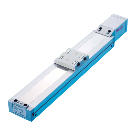
• EAS Series
Model Actuator model Driver model
EAS4--KD-EASM4K
EAS4-M-KD-EASM4MK
EAS6--KD-EASM6K
EAS6-M-KD-EASM6MK
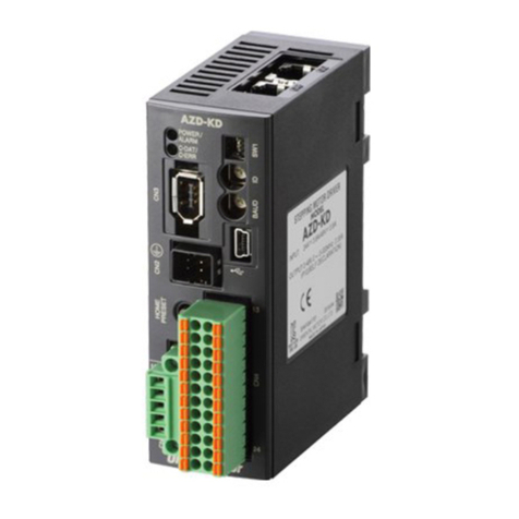
LSD-KD
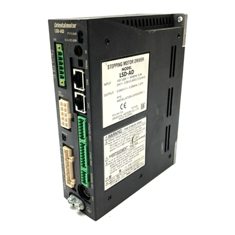
Names and functions of parts
Transmission rate setting
switch (SW2)
Address number setting
switch (SW1)
Data edit connector
(CN3)
Motor connector
(CN2)
CN1
Battery connector
(CN4)
POWER/ALARM LED C-DAT/C-ERR LED
Output signal connector
(CN9)
Input signal connector
(CN8)
Sensor signal connector
(CN5)
Power supply input
terminals
Electromagnetic
brake terminals
Frame Ground
Terminal
DIN lever
RS-485 communication
connectors (CN6/CN7)
Function setting switches (SW3)
Name Description
POWER/ ALARM LED
• POWER (Green): This LED is lit while
the main power is input.
• ALARM (Red): This LED will blink when
an alarm generates. It is possible to
check the generated alarm by counting
the number of times the LED blinks.
C-DAT/C-ERR LED
• C-DAT (Green): This LED will blink or
illuminate steadily when the driver is
communicating with the master station
properly via RS-485 communication.
• C-ERR (Red): This LED will illuminate
when a RS-485 communication error
occurs with the master station.
Address number
setting switch (SW1)
Use this switch when controlling the
system via RS-485 communication. Using
this switch in combination with the
SW3-No.1 of the function setting switch,
the address number (slave address) of
RS-485 communication can be set.
(Factory setting: 0)
Transmission rate
setting switch (SW2)
Use this switch when controlling the
system via RS-485 communication. Set
the transmission rate of RS-485
communication.
(Factory setting: 7)
Function setting
switches (SW3)
Use this switch when controlling the
system via RS-485 communication.
No.1: Using this switch in combination with
the address number setting switch
(SW1), the address number (slave
address) of RS-485 communication
can be set. (Factory setting: OFF)
No.2: The transmission rate of RS-485
communication can be set.
(Factory setting: OFF)
No.3: Not used.
No.4: Set the termination resistor (120 Ω)
of RS-485 communication.
(Factory setting: OFF)


