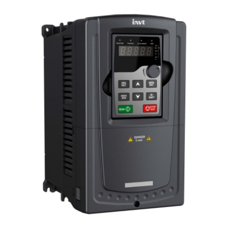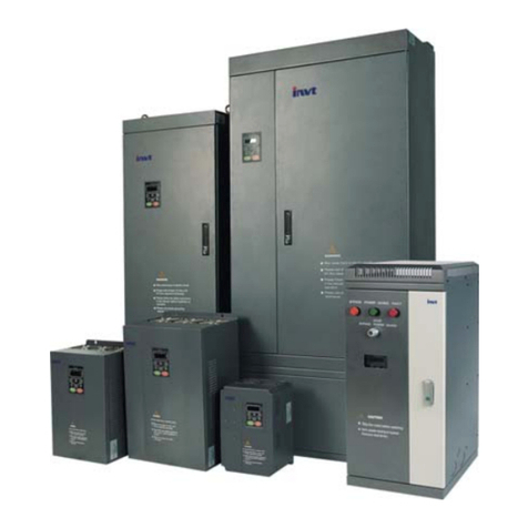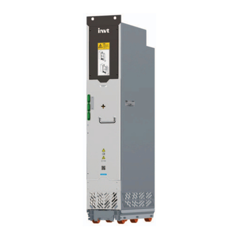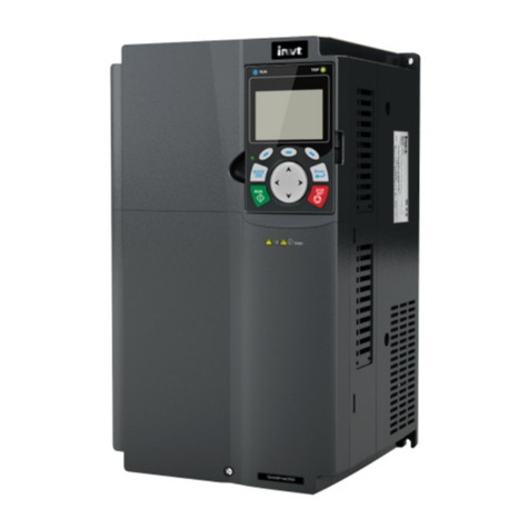
Goodrive20-UL Series VFD Contents
-iii-
7.2.2 RTU mode.........................................................................................................116
7.3 RTU command code and communication data .........................................................119
7.3.1 Command code 03H.........................................................................................119
7.3.2 Command code 06H.........................................................................................121
7.3.3 Command code 08H, diagnosis........................................................................122
7.3.4 Command code 10H, continuous writing..........................................................123
7.4 Data address definition..............................................................................................124
7.4.1 Function code address format rules .................................................................124
7.4.2 Description of other function addresses in Modbus..........................................124
7.4.3 Fieldbus scale...................................................................................................128
7.4.4 Error message response ..................................................................................129
7.5 Read/Write operation example..................................................................................131
7.5.1 Examples of reading command 03H ................................................................131
7.5.2 Examples of write command 06H.....................................................................132
7.5.3 Examples of continously writing command 10H...............................................133
7.6 Common communication faults .................................................................................135
Appendix A Technical data.................................................................................................136
A.1 Derated application ...................................................................................................136
A.1.1 Capacity............................................................................................................136
A.1.2 Derating............................................................................................................136
A.2 Marking......................................................................................................................137
A.2.1 CE marking.......................................................................................................137
A.2.2 UL and CUL marking........................................................................................137
A.2.3 Compliance with the European EMC Directive................................................137
A.3 EMC regulations........................................................................................................137
A.3.1 VFDs of category C2........................................................................................137
A.3.2 VFDs of category C3........................................................................................138
Appendix B Dimension drawings......................................................................................139
B.1 External keypad (optional) structure .........................................................................139
B.2 VFD chart..................................................................................................................140
Appendix C Optional peripheral accessories...................................................................142
C.1 Wiring of peripheral accessories...............................................................................142
C.2 Power supply ............................................................................................................144
C.3 Cables.......................................................................................................................144
C.3.1 Power cables....................................................................................................144
C.3.2 Control cables ..................................................................................................145
C.4 Fuse..........................................................................................................................145
C.5 Reactors....................................................................................................................146
C.6 Filter..........................................................................................................................147
C.6.1 C3 Filter model instruction ...............................................................................147
C.6.2 C3 filter.............................................................................................................148
