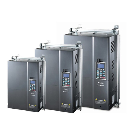
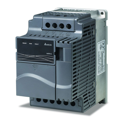
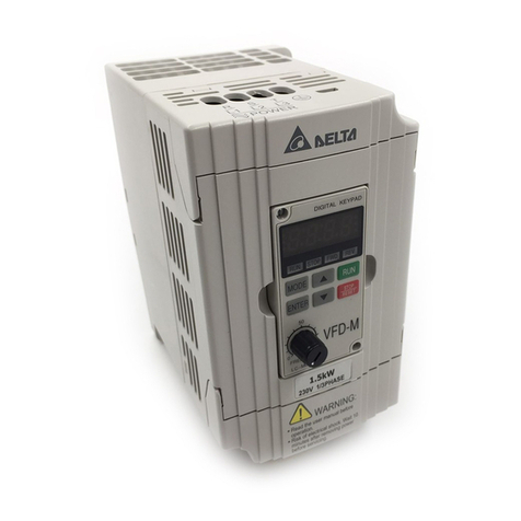
Delta VFD-EL-C Series User manual

www.deltaww.com
Digitized Automation for a Changing World
Delta CANopen Communication
Compact Drive
*We reserve the right to change the information in this manual without prior notice.
Taiwan:
Taoyuan Technology Center
No.18, Xinglong Rd., Taoyuan District,
Taoyuan City 33068, Taiwan
TEL:-3-362-6301 / FAX:-3-371-6301
China: ()
No.182 Minyu Rd., Pudong Shanghai, P.R.C.
-21-6872--21-6872-
Customer Service: 400-820-
Japan:(Japan)
Industrial Automation Sales Department
2-1-14 Shibadaimon, Minato-ku
-0012
-3---3--
Korea: (Korea)
--gu,
-2---2--
()
-
-6747--6744-
India: (India)
-124--124-
Thailand: (Thailand)
(E.P.Z),
Pattana 1 Rd., T.Phraksa, A.Muang,
Samutprakarn 10280, Thailand
--2800 / FAX66-2-2827
()
Mail: IA.au@deltaww.com
()
--767---767-
Brazil:
-12---12--237
--3603-
()B.V.
Sales: Sales.IA.EMEA@deltaww.com
Marketing: Marketing.IA.EMEA@deltaww.com
Technical Support: iatechnicalsupport@deltaww.com
Customer Support: Customer-Support@deltaww.com
Service: Service.IA.emea@deltaww.com
(0)
()B.V.
(0)
()B.V.
-
(0)
France:(France)
Mail: Sales.IA.FR@deltaww.com
(0)
Iberia:()
(0)
Mail: Sales.IA.Iberia@deltaww.com
()
(CO)
Mail: Sales.IA.Italy@deltaww.com
Mail: Sales.IA.RU@deltaww.com
()
-A
Mail: Sales.IA.Turkey@deltaww.com
()
Jumeirah Lakes Towers, Dubai, UAE
Mail: Sales.IA.MEA@deltaww.com
(0)
Delta CANopen Communication Compact Drive -
VFD-EL-C Series User Manual
I
Copyright notice
©Delta Electronics, Inc. All rights reserved.
All information contained in this user manual is the exclusive property of Delta Electronics Inc.
(hereinafter referred to as "Delta ") and is protected by copyright law and all other laws. Delta retains the
exclusive rights of this user manual in accordance with the copyright law and all other laws. No parts in
this manual may be reproduced, transmitted, transcribed, translated or used in any other ways without
the prior consent of Delta.
Limitation of Liability
The contents of this user manual are only for the use of the product manufactured by Delta. Except as
defined in special mandatory laws, Delta provides this user manual “as is” and does not offer any kind of
warranty through this user manual for using the product, either express or implied, including but not limited
to the following: (i) this product will meet your needs or expectations; (ii) the information contained in the
product is current and correct; (iii) the product does not infringe any rights of any other person. You shall
bear your own risk to use this product.
In no event shall Delta, its subsidiaries, affiliates, managers, employees, agents, partners and licensors
be liable for any direct, indirect, incidental, special, derivative or consequential damages (including but not
limited to the damages for loss of profits, goodwill, use or other intangible losses) unless the laws contains
special mandatory provisions to the contrary.
Delta reserves the right to make changes to the user manual and the products described in the user
manual without prior notice and afterwards.

II
Thank you for using Delta's compact built-in CAN communication drive VFD-EL-C series.
The VFD-EL-C series is manufactured using high-quality components, materials and incorporating the
latest embedded control technology.
This product description provides users with precautions related to installation, parameter setting,
abnormal diagnosis, troubleshooting and daily maintenance of the drive. In order to ensure correct
installation and operation, please read this product manual carefully before installing the drive, and please
keep it properly and hand it over to the user of the machine.
For the safety of the operator and mechanical equipment, it must be installed, tested and adjusted by
professional electrical engineering personnel. There are symbols such as [Danger] and [Caution] in this
product description. Please be sure to read it carefully. If you have any doubts, please contact our agents.
PLEASE READ PRIOR TO INSTALLATION FOR SAFETY.
Disconnect AC input power before connecting any wiring to the AC motor drive.
Even if the power has been turned off, a charge may still remain in the DC-link
capacitors with hazardous voltages before the POWER LED is OFF. Do not touch
the internal circuits and components.
There are highly sensitive MOS components on the printed circuit boards.
These components are especially sensitive to static electricity. Take anti-static
measures before touching these components or the circuit boards.
Never modify the internal components or wiring.
Ground the AC motor drive by using the ground terminal. The grounding method
must comply with the laws of the country where the AC motor drive is to be
installed.
This series is used to control the variable speed operation of three-phase induction
motors, and cannot be used for single-phase motors or for other purposes.
This series cannot be used in situations that endanger personal safety.
Please prevent children or general irrelevant persons from approaching the drive.
Never connect the AC motor drive output terminals U/T1, V/T2 and W/T3 directly
to the AC mains circuit power supply.
Do not perform withstand voltage test on the components inside the drive
, the
semiconductor used in the drive is easily damaged by high voltage breakdown.
Even if the three-phase AC motor is stopped, a charge with hazardous voltages
may still remain in the main circuit terminals of the AC motor drive.
Only qualified persons are allowed to install, wire and maintain the AC motor
drives.
When using an external terminal as the source of the running command, the motor
may start to run immediately after the power is input. It may cause danger if there
are people near the drive.
Install the drive in a safe area to prevent high temperature and direct sunlight, and
avoid splashing of moisture and water droplets.
Please comply with the installation precautions when installing the drive.
Unapproved use environment may cause fire, gas explosion, electric shock and
other incidents.

III
When the wiring between the drive and the motor is too long, the interlayer
insulation of the motor may be damaged. Please use an AC motor dedicated to
the drive, or install a reactor between the drive and the AC motor (refer to
Appendix A) to avoid damage to the AC motor due to insulation damage.
The rated voltage of power system to install motor drives is listed below. Ensure
that the installation voltage is in the correct range when installing a motor drive.
For 230V models, the range is between 180–264 V.
For 460V models, the range is between 342–528 V.
If the motor drive produces a leakage current of over AC 3.5mA or over DC 10mA,
the minimum specifications required of the Protective Earthing conductor have to
be a copper wire with a cross-sectional area of at least 10 mm2, an aluminum wire
with a cross-sectional area of 16 mm2, or install an earth leakage circuit breaker.
NOTE:
In the pictures in this manual, the cover or safety shield is disassembled only when explaining the
details of the product. During operation, install the top cover and wiring correctly according to the
provisions. Refer to the operation descriptions in the manual to ensure safety.
The figures in this instruction are only for reference and may be slightly different depending on your
model, but it will not affect your customer rights.
The content of this manual may be revised without prior notice. Consult our distributors or download
the latest version at http://www.deltaww.com/iadownload_acmotordrive.

IV
Table of Contents
CHAPTER 1 USE AND INSTALLATION.................................................................................. 1-1
1-1 Product Profile............................................................................................................1-3
1-2 Product Installation.....................................................................................................1-8
1-3 Product Dimensions...................................................................................................1-11
CHAPTER 2 WIRING ............................................................................................................... 4-1
2-1 Wiring Instructions……...............................................................................................2-3
2-2 System Wiring Diagram..............................................................................................2-7
2-3 Main circuit terminal description..................................................................................2-8
2-4 Control circuit terminal description.............................................................................2-11
2-5 NPN and PNP modes.................................................................................................2-13
CHAPTER 3 OPERATION PANEL DESCRIPTION AND TEST RUN...................................... 3-1
3-1 Panel Description….....................................................................................................3-3
3-2 Operation mode……....................................................................................................3-6
3-3 Test run...…..................................................................................................................3-8
CHAPTER 4 SPECIFICATION ................................................................................................. 4-1
4-1 230V 1φ Models……………….………………….......................................................4-2
4-2 460V 3φModels…………………………......................................................................4-3
4-3 General Specifications……………………………………………………………………...4-4
4-4 Environmental Specifications…………………..……….…………………….................4-5
4-5 Operating ambient temperature and Carrier Derating..…………...............................4-6
CHAPTER 5 CANopen OVERVIEW........................................................................................ 5-1
5-1 CANopen Ovreview.....................................................................................................5-3
5-2 Wiring for CANopen....................................................................................................5-7
5-3 CANopen Communication Interface Descriptions.......................................................5-8
5-4 CANopen Supporting Index......................................................................................5-16
5-5 CANopen Fault Codes..............................................................................................5-21
5-6 CANopen LED Function............................................................................................5-23
CHAPTER 6 DESCRIPTIONS OF PARAMETER SETTINGS .............................................. 6-1-1
6-1 Summary of Parameter Settings ………………………………………………………6-1-2
6-2 Descriptions of Parameter Settings…………………………………………………6-2-001
00 Drive Parameters…………………………………………………………….…6-2-001
01 Basic Parameters……………………………………………………………….6-2-011
02 Digital Input / Output Parameters……………………………………………..6-2-021
04 Multi-Stage Speed Parameters…………………………………………….....6-2-041

V
05 Motor Parameters………………………………………………………………...6-2-051
06 Protection Parameters (1) …………………………………………………....6-2-061
07 Special Parameters…………………………………………………………....6-2-071
09 Communication Parameters……………………………………………….....6-2-091
10 Speed Feedback Control Parameters…………………………………….....6-2-101
12 System control and CANopen function Parameters……………………......6-2-121
13 Control Mode Parameter Macro Function……………………………………6-2-131
CHAPTER 7 WARNING CODES ..............................................................................................7-1
CHAPTER 8 FAULT CODES ....................................................................................................8-1
APPENDIX A. MODBUS PROTOCOL…………………………………..………………………..A-1
A-1 Circuit Breaker…………..........................................................................................A-2
A-2 Reactors.................................................................................................................A-2
A-3 Remote Operation Keypad.........................................................................................A-4
A-4 The Assembly of Fan Kit.............................................................................................A-9
A-5 CANopen Accessories...............................................................................................A-16
Issued Edition: 02
Firmware Version: V1.04 (Refer to Parameter 00-06 on the product to get the firmware version.)
Issued Date: 2023/3

VI
[This page intentionally left blank]

Chapter 1 Use and InstallationEL-C
1-1
Chapter 1Use and Installation
1-1 Product Profile
1-2 Product Installation
1-3 Product Dimensions

Chapter 1 Use and InstallationEL-C
1-2
The product should be in the box when customers received. If the machine is not used temporarily, for the
safety of the maintenance during the warranty period of our company, be sure to pay attention to the
following points when storing the machine:
The machine must be placed in a ventilated, dust-free and dry location.
The ambient temperature of the storage location must be in the range of -
20°C to
+60°C.
The relative humidity of the storage location must be in the range of 0% to 90% with
no condensation.
Avoid storing the machine in environments containing corrosive gases or liquids.
Avoid placing the machine on the ground, but should place it on a suitable stand. And
place a desiccant in the packaging bag if the surrounding environment is harsh.
Avoid installing the machine in places exposed to direct sunlight or vibrations.
Even
if the humidity meets the specification requirements, condensation and freezing
may occur when the temperature changes sharply which location should be avoided.
If the machine has been opened and used for more than 3 months, the ambient
temperature of the
storage environment should not be higher than 30°C. It is
considered that when the electrolytic capacitor is stored without electricity, its
characteristics are easily deteriorated when the ambient temperature is too high. Do
not leave the machine unpowered for more than a year.
When the motor drive is installed in a device or control panel and is not in use
(especially in a construction site or in a humid and dusty place), the drive should be
removed and placed in a suitable environment meets the above-men
tioned storage
conditions.

Chapter 1 Use and InstallationEL-C
1-3
1-1 Product Profile
Each VFD-EL-C is subject to strict quality control and enhanced anti-collision packaging before shipment.
After the customer unpacks the drive, please carry out the following inspection steps immediately.
Check whether the drive has been damaged during transportation.
After unpacking, check the model of the drive is consistent with the data in the outer box.
If there is any inconsistency with your ordering information or any questions about the product, please contact
the agent or distributor.
Nameplate Information
Take 1 HP/0.4 kW 230V 1-Phase as an example
Model Name
Serial Number

Chapter 1 Use and InstallationEL-C
1-4
Appearance
Frame A1
Input terminals
(R/L1, S/L2, T/L3)
Digital keypad
Control board cover
Output terminals
(U/T1, V/T2, W/T3)
Ground terminals
A: Digital keypad
B: Control terminals
C: CAN Connect 1
(RJ45)
D: CAN Connect 2
(RJ45)
Frame A2
Input terminals
(R/L1, S/L2, T/L3)
Digital keypad
Control board cover
Output terminals
(U/T1, V/T2, W/T3)
Ground terminals
A: Digital keypad
B: Control terminals
C: CAN Connect 1
(RJ45)
D: CAN Connect 2
(RJ45)

Chapter 1 Use and InstallationEL-C
1-5
Frame B
Input terminals
(R/L1, S/L2, T/L3)
Digital keypad
Case
Control board cover
Output terminals
(U/T1, V/T2, W/T3)
Ground terminals
A: Digital keypad
B: Control terminals
C: CAN Connect 1
(RJ45)
D: CAN Connect 2
(RJ45)
Frame Capacity Model
A1 Keypad
Panel Mounting:
0.25–1 HP
(0.2–0.75 kW) VFD002EL21C, VFD004EL21C / 43C, VFD007EL21C / 43C
A2 2 HP (1.5 kW) VFD015EL43C
B 2–5.5 HP
(1.5–5.5 kW)
VFD015EL21C, VFD022EL21C / 43C,
VFD040EL43C, VFD055EL43C
Table 1-1
RFI Jumper switch
NOTE:
If the grounding system is required or the leakage current is too large to cause the
leakage protection
device to trip, loosen the screws next to the input side of (R/L1, S/L2, T/L3) and remove the grounding
short-circuit metal sheet.
Note: To re-tighten the loosened screws to keep the grounding well to prevent electric shock after
removing the grounding shorting piece.

Chapter 1 Use and InstallationEL-C
1-6
RFI Jumper
RFI Jumper:
(1) The drive contains Varistors / MOVs that are connected from phase to phase and from phase to
ground to prevent the drive from unexpected stop or damage caused by mains surges or voltage
spikes. Because the Varistors / MOVs from phase to ground are connected to ground with the
RFI jumper, removing the RFI jumper disables the protection.
(2) The RFI jumper connects the filer capacitors to ground to form a return path for high frequency
noise in order to isolate the noise from contaminating the mains power. Removing the RFI jumper
strongly reduces the effect of the built-in EMC filter. Although a single drive complies with the
international standards for leakage current, an installation with several drives with built-in EMC
filters can trigger the RCD. Removing the RFI jumper helps, but the EMC performance of each
drive is no longer guaranteed.
Isolating main power from ground:
When the power distribution system for the drive is a floating ground system (IT Systems) or an
asymmetric ground system (Corner Grounded TN Systems), you must remove the RFI jumper.
Removing the RFI jumper disconnects the internal capacitors from ground to avoid damaging the
internal circuits and to reduce the ground leakage current.
Pay particular attention to the following points:
Do not remove the RFI jumper while the power is on.
Make sure the main power is OFF before removing the RFI jumper.
Removing the RFI jumper also cuts the capacitor conductivity of the surge absorber to ground
and the capacitors. Compliance with the EMC specifications is no longer guaranteed.
Reliable electrical isolation cannot be maintained if the ground shorts are removed. In other words, all
control inputs and outputs can only be regarded as low-voltage terminals with basic electrical isolation.
In addition, the electromagnetic compatibility of the frequency converter will be reduced by removing
the grounding shorts.
Do not remove the RFI jumper if the mains power is a symmetrical grounded power system in
order to maintain the efficiency for EMC filter.
The short-circuit piece must be removed during the high voltage test, and be sure to tighten the
screws securing the shorting strip after removing the shorting strip. When conducting a high
voltage test to the entire facility, disconnect the mains power and the drive if the leakage current
is too high.
If the drive is installed in a non-grounded power system or a high-impedance grounded power
system (over 30Ω) or a corner-grounded TN system, the grounding short must be removed to
avoid the machine damage. After removing the jumper, the screws fix the jumper must be
tightened.

Chapter 1 Use and InstallationEL-C
1-7
Remove step
Remove the control terminal slide
Press the control board terminal slide cover lightly as
shown in Figure A first, and then slide it down as shown
in Figure B to remove it easily.
Figure A
Figure B
Remove the fan
Frame B
Press the buckles on the left and right sides of
the fan lightly and pull up to remove the fan.

Chapter 1 Use and InstallationEL-C
1-8
1-2 Product Installation
Please install the drive in the following environmental conditions to ensure the safety of the product:
NOTE:
1. The VFD007EL21C needs to install the fan accessory MKEL-AFKM1, and the upper limit of the
ambient temperature operation can reach 50°C.
Operating
Environmental
Conditions
Ambient
temperature -10°C–+50°C NOTE 1
Rated
Humidity < 90%, no frosting
Air Pressure 86–106 kPa
Altitude < 1000 m
Vibration
1.0 mm, peak to peak value range from 2–13.2 Hz; 0.7–1.0
G range
from 13.2–55 Hz; 1.0 G range from 55–512
Hz. Compliance with IEC
6006826
Storage /
Transportation
Ambient
temperature -20°C–+60°C (-4°F–140°F)
Rated
Humidity < 90%, no frosting
Air Pressure 86–106 kPa
Vibration
1.0 mm, peak to peak value range from 2–13.2 Hz; 0.7–1.0
G range
from 13.2–55 Hz; 1.0 G range from 55–512
Hz. Compliance with IEC
6006826
Pollution Degree
Level 2: Suitable for low-to-medium pollution factory environments
Table 1-2

Chapter 1 Use and InstallationEL-C
1-9
Mounting Clearance
Inflow
Outflow
Distance
Single drive
installation
Side-by-side horizontal installation Zero stack installation
Model Installation
Method
Minimum distance (mm)
Ambient temperature (ºC)
A B C NOTE 1
Max.
(Without derating)
Max.
(derating)
VFD002EL21C
VFD004EL21C
VFD004EL43C
Single drive
installation
120 50 - 50 60
Side-by-side
horizontal
installation
120 50 30 50 60
Zero stack
installation
- - - - -
VFD007EL21C
Single drive
installation
120 50 - 50 NOTE 4 60
Side-by-side
horizontal
installation
120 50 30 50 NOTE 4 60
Zero stack
installation
- - - - -
VFD007EL43C
VFD015EL43C
Single drive
installation
120 50 - 50 60
Side-by-side
horizontal
installation
120 50 30 50 60
Zero stack
installation
- - - - -
VFD015EL21C
VFD022EL21C
VFD022EL43C
VFD040EL43C
VFD055EL43C
Single drive
installation
150 50 - 50 60
Side-by-side
horizontal
installation
150 50 30 50 60
Zero stack
installation
150 50 0 40 50
Table 1-3
NOTE:
1. The shape of the heat sink of frame A1 / A2 protrudes from the left and right plastic shell bodies,
therefore, the horizontal side-by-side installation distance C is calculated based on the position of
the plastic shell of the drive.
2. Frame A1 / A2 does not support zero stack installation. Frame B supports zero stack installation.
3. When the ambient temperature exceeds the column of "Max. (without derating)", full load operation
will shorten the service life of the drive.

Chapter 1 Use and InstallationEL-C
1-10
4. When the model VFD007EL21C is equipped with a fan accessory, the upper limit of the ambient
operating temperature is as shown in the table above; when there is no fan accessory, the upper limit
of the corresponding ambient operating temperature is 10ºC lower than the temperature value in the
table (refer to Appendix B-3-3 for the installation of fan accessories).
The drive should be installed vertically on a solid structure with screws. Do not install it upside
down, obliquely or horizontally.
Heat is generated when the drive is running. To ensure the passage of cooling air should be as
shown. The design leaves a certain space that the heat generated can be dissipated upwards. Do
not install it under the equipment which is not heat-resistant. It is necessary to consider ventilation
and heat dissipation in the control panel to ensure the ambient temperature of the drive does not
exceed the specified value. Do not install the drive in an airtight box with poor ventilation and heat
dissipation, which may easily cause machine failure due to overheating
When the drive is running, the temperature of the heatsink plate can rise up to nearly 90ºC.
Therefore, the mounting surface on the back of the drive must be made of a metal material which
can withstand higher temperatures and have good heat dissipation.
To installing multiple drives in the same control panel, it is recommended to install them
horizontally side by side in order to reduce mutual thermal influence. If upper and lower
installations are required, a partition plate must be installed to reduce the effect of the heat
generated in the lower part on the upper part.
Partition plate setting
Without partition plate setting
NOTE:
Prevent fiber particles, scraps of paper, shredded wood, sawdust, metal particles, etc. from adhering to
the heat sink.
Install the AC motor drive in a metal cabinet. When installing one drive below another one, use a metal
separator between the AC motor drives to prevent mutual heating and to prevent the risk of fire accident.
Air flow
Frame A Frame B
Frame A Frame B

Chapter 1 Use and InstallationEL-C
1-11
1-3 Product Dimensions
Frame A1
VFD002EL21C, VFD004EL21C, VFD004EL43C, VFD007EL21C, VFD007EL43C
Unit: mm [inch]
Frame
W
W1
H
H1
D
D1
S1
A1
92.0
[3.62]
82.0
[3.23]
162.0
[6.38]
152.0
[5.98]
128.7
[5.07]
2.0
[0.08]
5.4
[0.21]
Table 1-4
Detail A (Mounting Hole)
D
S1
W1
W
H1
H
See Detail A
D1

Chapter 1 Use and InstallationEL-C
1-12
Frame A2
VFD015EL43C
Unit: mm [inch]
Frame
W
W1
H
H1
H2
D
D1
S1
A2
92.0
[3.62]
82.0
[3.23]
180.5
[7.11]
162.0
[6.38]
152.0
[5.98]
128.7
[5.07]
2.0
[0.08]
5.4
[0.21]
Table 1-5
S1
Detail A (Mounting Hole)
See Detail A
D
W1
W
H1
H
H2
D1

Chapter 1 Use and InstallationEL-C
1-13
Frame B
VFD015EL21C, VFD022EL21C, VFD022EL43C, VFD040EL43C, VFD055EL43C
Unit: mm [inch]
Frame
W
W1
H
H1
D
D1
S1
S2
B
100.0
[3.94]
89.0
[3.50]
174.0
[6.85]
162.9
[6.42]
136.0
[5.35]
4.0
[0.16]
5.9
[0.23]
5.4
[0.21]
Table 1-6
S2
S1
D1W1
H1
W
H
D
Detail A (Mounting Hole) Detail B (Mounting Hole)
See Detail A
See Detail B
Table of contents
Other Delta DC Drive manuals

Delta
Delta PMC-24V150W1AA User manual

Delta
Delta C2000 Plus Series User manual

Delta
Delta C2000 Series User manual

Delta
Delta CP2000 Series User manual

Delta
Delta VFD-ME300 Series Manual

Delta
Delta C2000 Series User manual

Delta
Delta VFD-B 230V Series User manual

Delta
Delta IED-S Series User manual

Delta
Delta C2000 Series User manual

Delta
Delta VFD-EL-W Series User manual

Delta
Delta CP2000 Series User manual

Delta
Delta MH300 User manual

Delta
Delta MS300 Series User manual

Delta
Delta VFD-A User manual

Delta
Delta VFD-E User manual

Delta
Delta VFD-MS300 Series Manual

Delta
Delta VFD-ED Series User manual

Delta
Delta VFD-B Series User manual

Delta
Delta VFD-M Series User manual

Delta
Delta VFD-EL-W Series User manual