EN • 6
ENGLISHFRANCAISNEDERLANDSESpAñoLITALIANoDEuTSCH
662Y0500 • B
INSTALLATION
DIMENSIONS
When the burner is mounted to a boiler, the following dimensions
must be observed:
- Bolt circle: Ø 150 mm ± 1.5 mm
- Boiler door bore: min Ø 91 mm
INSTALLATION INSTRUCTIONS
When installing the oil hoses and connection wire, make sure that
the connection is strain-relieved and that the burner can be easily
placed in the service mounting bracket.
To commission the oil supply system, it must be vented via the
manometer connection of the oil pump.
Make sure that there are no leaks in the oil supply system!
Failure to do so can lead to combustion problems and dripping.
Replace the oil filter unit at the same time as replacing the burner!
Do not reverse phase and Mp!
Make sure that the protective earth conductor is properly
connected!
SYSTEM CHECK
Correct installation by a specialist company should include the
following:
1. Correct installation of oil lines and filter, leak testing and filling
with oil.
2. Compliance with relevant provisions of the Federal Water Act
(Wasserhaushaltsgesetz, WHG) relating to the laying of oil
lines and the anti-siphoning device.
3. Electrical connections must be installed in compliance with
local regulations. Use flexible cable for the burner connection.
4. The temperature of the oil in the storage tank and the oil lines
must be at least +5 degrees C.
5. Make sure that cold outside air cannot be drawn in.
BURNER ASSEMBLY
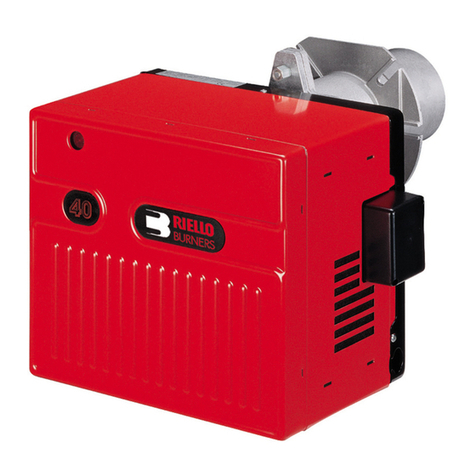
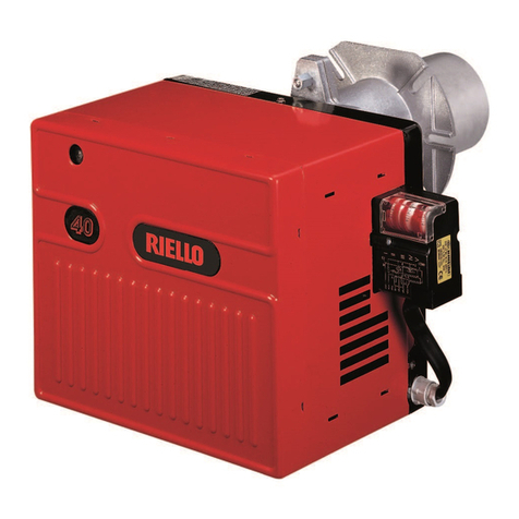
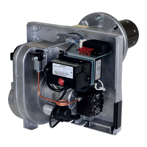
The BMR blue burner is particularly suitable for installing in
standard boilers (intermittent operation) for providing domestic
heating and hot water. Our design and development and test
conditions are precisely matched to these operating conditions.
SPECIAL APPLICATIONS
Special requirements and operating conditions must be observed
for the following fields of application:
• Dark radiators
• Ovens
• Drying chambers
• Annealing furnaces
• Industrial applications
Please seek our approval before using the burner in these applications!
It is advisable to consult ACV in the event of increased load in the
combustion chamber or increased thermal load.
Do not allow contaminated combustion air to enter the
burner!
This can be prevented by taking appropriate precautions,
particularly in areas contaminated with halohydrocarbons (printing
shops, hair salons, dry cleaners, laboratories).If in doubt, please
contact us.
Avoid excessive dust accumulation when the burner is
operating!
Avoid high air humidity and frost!
Good ventilation is essential!
We accept no liability for non-compliance with these
recommendations!
RECIRCULATION
The recirculation slots must on no account be covered by the door
cladding. Chamfer the door cladding as shown in the diagram if
necessary.
M 8
150
91
Flange adjustment
Chamfered door cladding
This recirculation opening must be kept clear
This mounting bracket must not be damaged


