ACV EVO S Grundfos Magna 1 C User manual

EVO S
Pump Kit
Grundfos Magna 1 Model C
When replacing any part on this
appliance, use only spare parts that you
can be assured conform to the safety
and performance specification that we
require. Do not use reconditioned or
copy parts that have not been clearly
authorised by ACV.
For the very latest copy of literature for
specification and maintenance practices
visit our website www/acv/com/gb
where you can download the relevant
information in PDF format.
Instructions
03/2023
UIN 236076 A01


ACV UK Ltd Evo S
1
236076 A01
CONTENTS
Section 1 - General...................................................................................2
1.1 Introduction.................................................................................2
1.2 Contents .....................................................................................2
Section 2 - Installation ..............................................................................3
2.1 Preparation .................................................................................3
2.2 Installation...................................................................................3
2.3 Pump Connections ....................................................................4
2.4 Operating Panel .........................................................................5
2.5 Setting The Control Function......................................................5
2.6 Control Functions........................................................................6

This kit includes the following items:
1.1 INTRODUCTION
1.2 CONTENTS
This kit is suitable for the Evo S 150.
This manual explains how to install the Pump Control
kit and determine the pump settings.
The Pump control kit converts the demand signal from
the boiler pump QX3 mains voltage output into a Volts
Free enable signal for the Grundfos Magna 1 Model C
SELV Start/Stop input signal.
Item Description
1. Relay Module Kit
2. Instructions
ACV UK Ltd Evo S
2
236076 A01
Section 1 - General

1. Connect the cables from the left-hand side of the relay
onto connection QX3, L3, connection 9-brown (live) and
connection 10-blue (neutral) on the boiler wiring strip.
2. Make sure that the right-hand side cable from the relay
goes through the provided cable clamp.
3. Insert the relay module into the space between the Mains
voltage and PELV installer connection terminals.
2.1 PREPARATION
2.2 INSTALLATION
Install the Pump Control kit as follows:
WARNING: Be careful when you install electrical
connections. Electric shock can cause serious injury or
death and can cause damage to equipment.
1. Make sure that the electrical power supply to the boiler is
set to OFF. For safe electrical isolation refer to Gas Safe
technical bulletin 118. All work must be carried out by a
competent person.
2. For access to the control box (refer to refer to manual
Evo S INSTALLATION, COMMISSIONING AND
SERVICING INSTRUCTIONS Frame 4.6.1).
2
ACV UK Ltd Evo S
3
236076 A01
Section 2 - Installation
1
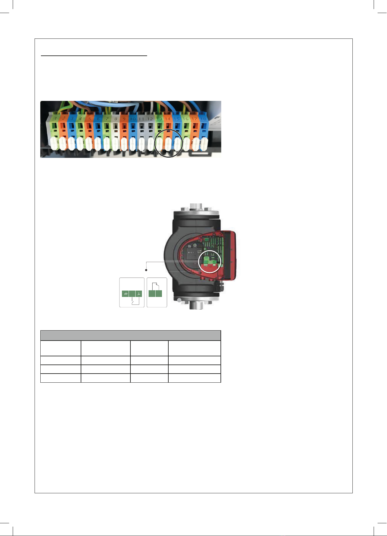
2.3 PUMP CONNECTIONS
Mains Voltage Connections 230 VAC
1. Connect a suitable 3 core cable between the Boiler and the Pump. 13-Green/Yellow (PE), 14-brown (live) and 15-blue
(neutral) on the boiler wiring strip, this provides the permanent supply to the pump.
2. Secure the Pump supply cable into the cable clamp at the boiler and the cable retention at the Pump.
In the supplied Grundfos Installation & Operating instructions refer to ‘Connection to the power supply, terminal-connected
Version’.
For the connection from the relay, refer to the supplied Grundfos installation and operating instructions ‘Digital input (Start/
Stop)’.
During the commissioning procedure, to achieve a temperature dierential
of 20°C at maximum rate, adjust the pump curve following the pump
manufacturer’s instructions.
S/S NC C
Evo S 150
Hydraulic
Conguration
Flow Rate
Q (m3/hr) ∆t 20°C Head (m) Pump Used
No separation 6.22 9.99 Magna 1 32 - 120F
LLH 6.22 10.19 Magna 1 32 - 120F
PHEX 6.28 11.52 Magna 1 40 - 150F
Section 2 - Installation
ACV UK Ltd Evo S
4
236076 A01
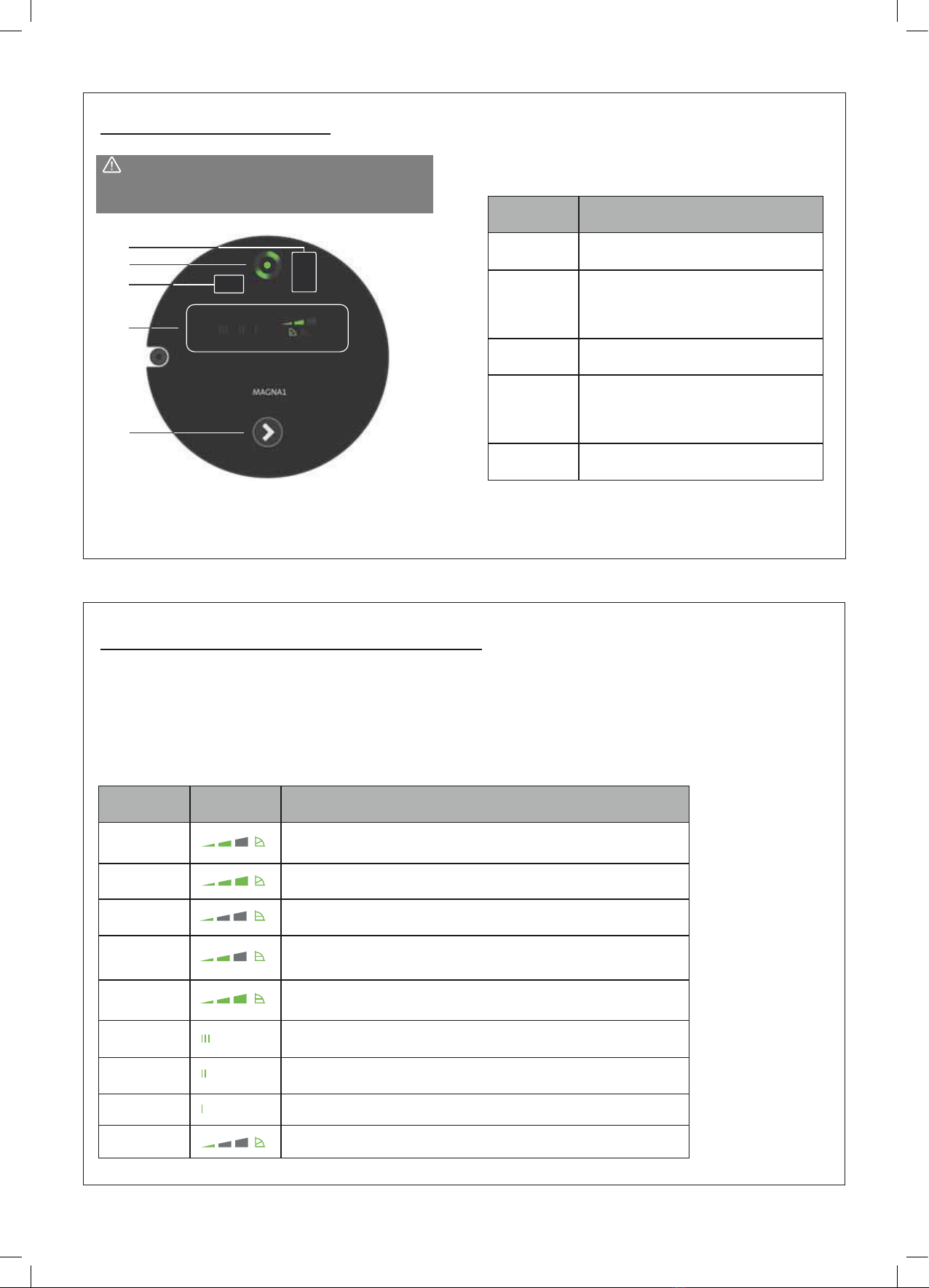
2.4 OPERATING PANEL
2.5 SETTING THE CONTROL FUNCTION
CAUTION: Hot surface - minor or moderate
personal injury. To avoid burns, only touch the
operating panel.
1
3
4
2
5
The operating panel on the pump comprises of the
following:
Position Description
1Infrared receiver for Grundfos GO.
Plug-connected versions.
2
Grundfos Eye.
Refer to Section 9.1 in the
Grundfos Magna1 Installation &
Operating instructions.
3Infrared receiver for Grundfos GO.
Terminal-connected versions.
4
LEDs indicate the control function.
Refer to Section 8.2 in the
Grundfos Magna1 Installation &
Operating instructions.
5Push-button for selection of a control
function
Position Description
0Intermediate proportional-pressure curve, referred to as PP2 factory
setting.
1Highest proportional-pressure curve, referred to as PP3.
2Lowest constant-pressure curve, referred to as CP1.
3Intermediate constant-pressure curve, referred to as CP2.
4Highest constant-pressure curve, referred to as CP3.
5Constant curve III.
6Constant curve II.
7Constant curve I.
8Lowest proportional-pressure curve, referred to as PP1.
The pump has nine control functions, refer to section 7 Control
Functions in the Grundfos Magna1 Installation & Operating
instructions. Select the control function by pressing the push-button
on the operating panel, see section 2.4 Operating Panel. The control
function is indicated by eight dierent light elds in the display.
Section 2 - Installation
ACV UK Ltd Evo S
5
236076 A01

2.6 CONTROL FUNCTIONS
Factory setting: Intermediate proportional-
pressure curve, referred to as PP2.
Proportional-pressure curve (PP1, PP2 or PP3)
Proportional-pressure control adjusts the pump
performance to the actual ow rate demand in the
system, but the pump performance follows the
selected performance curve, PP1, PP2 or PP3. See
below where PP2 has been selected.
PP3
PP2
PP1
Q
H
The selection of the right proportional-pressure setting
depends on the characteristics of the system in
question and the actual ow rate demand.
For further information, refer to section 7.4 Overview
of the control functions and 7.5 Selecting control
function in the Grundfos Magna1 Installation &
Operating instructions.
Constant-pressure curve (CP1, CP2 or CP3)
Constant-pressure control adjusts the pump
performance to the actual ow rate demand in the
system, but the pump performance follows the
selected performance curve, CP1, CP2 or CP3. See
below where CP1 has been selected.
Q
H
CP3
CP2
CP1
The selection of the right constant-pressure setting
depends on the characteristics of the system in
question and the actual ow rate demand.
For further information, refer to section 7.4 Overview
of the control functions and 7.5 Selecting control
function in the Grundfos Magna1 Installation &
Operating instructions.
Constant curve (I, II or III)
At constant-curve operation, the pump runs at a
constant speed, independently of the actual ow
rate demand in the system. The pump performance
follows the selected performance curve, I, II or III. See
below where II has been selected.
Q
H
The selection of the right constant-curve setting
depends on the characteristics of the system in
question.
For further information, refer to section 7.4 Overview
of the control functions and 7.5 Selecting control
function in the Grundfos Magna1 Installation &
Operating instructions.
Section 2 - Installation
ACV UK Ltd Evo S
6
236076 A01
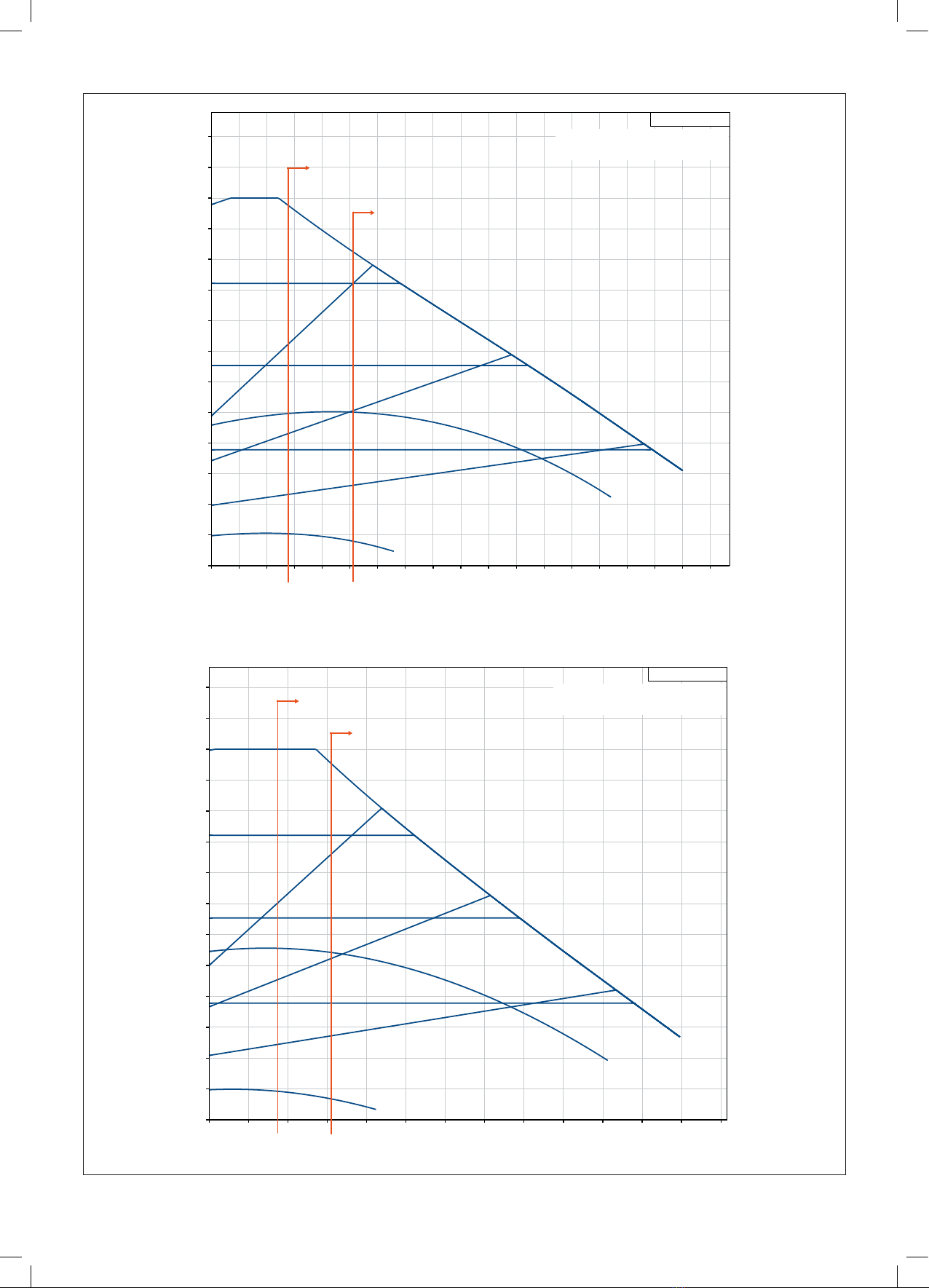
H
[m]
0
1
2
3
4
5
6
7
8
9
10
11
12
13
14
24 Q [m³/h]0 2 4 6 8 10 12 14 16 18 20 22
MAGNA1 40-150 F
Pumped liquid = Water
Liquid temperature during operation = 60 °C
Density = 983.2 kg/m³
3.44 6.23
Max Rate
Min Rate
H
[m]
0
1
2
3
4
5
6
7
8
9
10
11
12
13
17 Q [m³/h]0 1 2 3 4 5 6 7 8 9 10 11 12 13 14 15 16
MAGNA1 32-120 F
Pumped liquid = Water
during operation = 60 °CLiquid temperature
Density = 983.2 kg/m³
2.75 5.16
Max Rate
Min Rate
Section 2 - Installation
ACV UK Ltd Evo S
7
236076 A01

Notes
ACV UK Ltd Evo S
8
236076 A01

Notes
ACV UK Ltd Evo S
9
236076 A01

ACV pursues a policy of continuing improvement in the design and performance
of its products. The right is therefore reserved to vary specication without notice.
ACV U.K. Limited
St. David’s Business Park,
Dalgety Bay
Fife, Scotland
KY11 9PF
Tel: 0044 (0)1383 820100
www.acv.com/gb
Table of contents
Popular Water Pump manuals by other brands


Lincoln
Lincoln SKF J Series installation instructions

dosatron
dosatron D 45 RE 3000 owner's manual

Rietschle
Rietschle VACFOX VC 150 operating instructions

Oase
Oase NEPTUN 600 operating instructions

Gardner Denver
Gardner Denver WELCH MPC 301 Zp Ex Operation manual

Drum
Drum SSC150 Service and repair manual

Husqvarna
Husqvarna PP 325 E Operator's manual

Utilitech
Utilitech 148012 manual

Becker
Becker O2-PACK U5.70 operating instructions

Krautzberger
Krautzberger MP-400 operating instructions

Oase
Oase BioSmart 5000 operating instructions

GORMAN-RUPP PUMPS
GORMAN-RUPP PUMPS 11 1/2A22-B Installation, operation, and maintenance manual with parts list