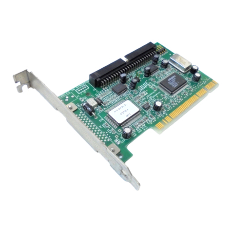
ACB-2070A
PRIMARV
FORMATIER
At
this
point, the disk must
be
formatted
with a primary
format. Primary formatting
is
not
supported
by
DOS
2.0;
however, it
is
supported
by
the ACB-2070A
BIOS
through
"DEBUG:'
Unlike other controllers, the ACB-2070A needs
no
extra software
to
perform the primaryformatting.
The
primaryformat defines address fields
and
data
fields
on
each
1tack
of
the
disk. After this
is
completed,
bad
blocks
can
be
flagged
and
a directory
created
by
a
DOS
"FORMAT"
command.
The
drive parameters,
i.e.,
answers
to
all questions,
can
be
inputted
by
a
DOS
redirected I/Ofile.
This
will
ease
integration
of
drive
and
controller
in
a manufacturing
environment.
NOTE:
A
customer-supplied
device
driver
is
needed
if
more
than
two
logical
units
are
used
or
more
than
64
MB
of
hard
disk
capacity
is
used.
Adaptec
does
not
supply
such a driver.
To
use the primaryformatter, perform the following steps:
1.
Boot
DOS
2.0 or newer revisions from the
DOS
SUPPLE-
MENTAL
PROGRAMS
diskette.
2.
Type
"DEBUG;'
the
computer
will respond with
0"-".
NOTE:
Underlined
characters
are
user inputs, <RET>
means
return key
and
parentheses
mean
comments.
A>DEBUG <RET>
--
(DEBUG
prompt)
3.
Type the following sequence:
-G = C800:CCC <RET>
•
..
ADAPTEC
ACB-2070A
FORMAT
PROGRAM···
Enter
sector interleave (3 to
9):Q
<RET>
3-to-1
is
the
optimum
interleave
factor
for the
IBM
PC/Xl
Experimentation with different interleave factors
is
the
best
way
of
determining the optimum interleaving
factor
for your
application.
3-to-1
is
the fastest interleave for
2.7
RLL
(7.5
Megabits/second) thatthe
IBM
PC/XT
can
accept.
Enter
Drive
ID
(0/1):Q
or.1 <RET>
7
This
value specifies which physical drive
is
to
be
formatted.
It
follows the hardware switch setting
on
the drives.
Should we use the defaultparameters
(y/N):,!,
or
~
<RET>
The
default
parameters refer
to
the current drive
table
selected
by
the jumpers for that drive
(0
or
1),
see
Tables 1
and
2.
You
have two choices: "Y" for
jumper
default
drive
parameters or
"N"
for user-defined drive parameters.
JUMPER
DEFAULT
DRIVE
PARAMETERS
("V"
RESPONSE)
A "Y" will invoke the
default
drive
table
selection as
defined
by
the jumpers M-N,
O-P,
E-F
for drive 0
and
jumpers Q-R,
S-T,
G-H for drive
1.
This
will skip
to
the
question for
defect
byte offset
encoding.
USER-DEFINED
DRIVE
PARAMETERS
("N"
RESPONSE)
An
"N"
will invoke the user-defined drive parameters
feature
described
below
and
will
ignore the
jumper
default
drive
table
selection.
NOTE:
The
following
parameters
are
for
the
Seagate
ST-238
drive
and
are
shown for
example
only
Insert yourdrive
param-
eters in
place
of
these.
The
Adaptec
ACB-2070A
controller
board
allows you
to
go
from
16
MB
to
64
MB
with
no
special
software.
NOTE:
Enter
all
values in
decimal.
Number
of
logical
units for
this
drive
(1-8):!'{!
<RET>
The
ACB-2070A allows you
to
partition a single physical
drive into
many
equal
logical
units.
The
units
can
be
up
to 32
MB
each
(a restriction
of
DOS
format) having a
maximum
of
eight units for
one
or two physical drives.
In
the
example
for the
ST-238
drive,if
M=2,
the 30
MB
physical drive will
be
divided
into two
equal
logical
units
of
15
MB
each.
Step pulse rate (0
to
7):~
<RET>
The
step pulse rate
is
defined
in
Table
4.
Many
drives
that
are currently
available
will provide high perfor-
mance,
i.e.,
lower
access
times, when used with option
3.
If
a slower nonbuffered step rate drive
is
used, option 0
is
required. Refer
to
the
Disk
Drive
OEM
Manual
for the
fastest
buffered
seek step rate.
8
TABLE
4.
SEEK
STEP
PULSE
RATES
Code
Seek Slep
Pulse
Rale
o
3.0
milliseconds
1 Reserved
2
30
microseconds
3
13
microseconds
4 200 microseconds
5
70
microseconds
6 Reserved
7 Reserved
Number
of
heads
(1
to
16
):~
<RET>
Number
of
cylinders:615 <RET>
For
other disk drives, see the
Disk
Drive
OEM
Manual
for
these values.
In
this
case,the drive has four
data
heads
and
615
cylinders. Minimum value
of
cylinders =
1.
maximum =
1024.
The following prompts
allow
the user
to
specifythe
method
of
entering defects.When entering a
defect
list,
it
may
be
put
in
a separatefile orenteredfrom the keyboard.
Specifythe Defect
Byte
Offset
encoding:
MFM or
RLL
(M/R)?!'{! org<RET>
All drive manufacturers give a
list
of
defective
areas
on the disk.
This
defect
list
gives the location
of
defects
in
one
of
two forms.
One
form
is
cylinder,
head
and
byte
offset.
The
other
is
head,
cylinder
and
byte offset. Normally
the byte offset
is
given
in
MFM
encoding.
Many
drive
vendors are also giving the byte offset
in
RLL
encoding.
Either
MFM
or
RLL
encoding
can
be
used.
If
MFM
is
used,
the controller multiplies
by
1.5
to
determine
the
RLL
equivalent defect.
If
no
defect
list
is
available,press 'M'then 'C'
and
two
<RET>'s.
The
controller will
flag
defects that it finds during
trackverification
in
data
and
ID
fields.
This
does
not
guarantee
thatall defectswill
be
detected
and
mapped.
Drive manufacturers
do
more
rigorous
analog
and
temperature
testing
to
create
their
defect
lists.
Enter
defect
list
as "Cyl/Head/Byte" or "Head/Cyl/Byte"
(C or
H):
g
or!::!
<RET>
Type
defect
file
name
or press
Enter:
Enter
the
defect
list
in
the format selected
above,
i.e
..
cyl/head/byte
or
head/cyl/byte.
The
cylinder,
head
and
byte offset are
separated
by
"I" marks.
For
example,
31/2/4054meanscylinder
31.
head
2
and
4054bytesoffset.
9
