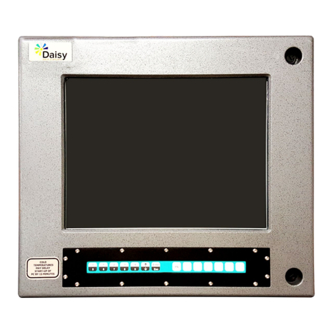
Adaptive Micro Systems Alpha 4000 RGB NEMA 12 User manual

ALPHA 4000 RGB NEMA 12, INSTALLATION MANUAL (PN 1778600401 REV. B)1-1
Alpha 4000 RGB NEMA 12
Installation Manual
Alpha 4000 RGB NEMA 12

1-2 ALPHA 4000 RGB NEMA 12, INSTALLATION MANUAL (PN 1778600401 REV. B)
Alpha 4000 RGB NEMA 12
© Copyright 2019 Adaptive Micro Systems LLC. All rights reserved.
Adaptive Micro Systems
7840 North 86th Street
Milwaukee, WI 53224 USA
414-357-2020
414-357-2029 (fax)
http://www.adaptivedisplays.com
Adaptive is a registered trademark of Adaptive Micro Systems. All other brand and product names are trademarks
or registered trademarks of their respective companies.

ALPHA 4000 RGB NEMA 12, INSTALLATION MANUAL (PN 1778600401 REV. B)1-3
Alpha 4000 RGB NEMA 12
Introduction . . . . . . . . . . . . . . . . . . . . . . . . . . . . . . . . . . . . . . . . . . . . . . . . . . . . . . . . . . 1-4
Temperature protection . . . . . . . . . . . . . . . . . . . . . . . . . . . . . . . . . . . . . . . . . . . . . . . . . 1-5
EMI compliance . . . . . . . . . . . . . . . . . . . . . . . . . . . . . . . . . . . . . . . . . . . . . . . . . . . . . . . 1-5
Environmental requirements . . . . . . . . . . . . . . . . . . . . . . . . . . . . . . . . . . . . . . . . . . . . . 1-5
Reducing electrical noise . . . . . . . . . . . . . . . . . . . . . . . . . . . . . . . . . . . . . . . . . . . . . . . . 1-5
Installation . . . . . . . . . . . . . . . . . . . . . . . . . . . . . . . . . . . . . . . . . . . . . . . . . . . . . . . . . . . 1-5
Connecting the power wires . . . . . . . . . . . . . . . . . . . . . . . . . . . . . . . . . . . . . . . . . . . 1-6
Connecting the communication wire(s). . . . . . . . . . . . . . . . . . . . . . . . . . . . . . . . . . . 1-7
Sign specifications. . . . . . . . . . . . . . . . . . . . . . . . . . . . . . . . . . . . . . . . . . . . . . . . . . . . . 1-8
Wall mounting. . . . . . . . . . . . . . . . . . . . . . . . . . . . . . . . . . . . . . . . . . . . . . . . . . . . . . . . . 1-9
Ceiling mounting. . . . . . . . . . . . . . . . . . . . . . . . . . . . . . . . . . . . . . . . . . . . . . . . . . . . . . 1-10
Start-up . . . . . . . . . . . . . . . . . . . . . . . . . . . . . . . . . . . . . . . . . . . . . . . . . . . . . . . . . . . . 1-11
Maintenance . . . . . . . . . . . . . . . . . . . . . . . . . . . . . . . . . . . . . . . . . . . . . . . . . . . . . . . . 1-11
Routine cleaning . . . . . . . . . . . . . . . . . . . . . . . . . . . . . . . . . . . . . . . . . . . . . . . . . . . . . 1-11
Service and repair . . . . . . . . . . . . . . . . . . . . . . . . . . . . . . . . . . . . . . . . . . . . . . . . . . . . 1-11
1 INTRODUCTION
2INSTALLATION
3START-UP
Sign overview. . . . . . . . . . . . . . . . . . . . . . . . . . . . . . . . . . . . . . . . . . . . . . . . . . . . . . . . . 1-4
Supplier's declaration of conformity . . . . . . . . . . . . . . . . . . . . . . . . . . . . . . . . . . . . . . . 1-12
4 COMPLIANCE

1-4 ALPHA 4000 RGB NEMA 12, INSTALLATION MANUAL (PN 1778600401 REV. B)
INTRODUCTION
Alpha 4000 RGB NEMA 12
Introduction
Item Name Description Item Name Description
ACEILING MOUNT
ATTACHMENT
POINTS
Optional ceiling mount.
Attach provided hanging
brackets here.
GCOMMUNICATION
ENTRY POINT
1/2 inch trade size hole (.875")
for communication wiring entry.
BMICRO SD
CARD ACCESS
PANEL
Removable panel to access
micro SD card.
H
CREAR BRACKET
MOUNT
Attach wall mounting brackets
at this location.
I
POWER ENTRY
POINT
CABLE TIE WRAP
MOUNT
Tie wrap mount for cable
management (if needed).
DREAR
COMMUNICATION
ACCESS PANEL
Removable panel to
access RS232, RS485, or
Ethernet communication
input connections.
D
CC
A
B
J
Top View
Back View
Bottom View
FF
EH
G
IK
EREAR POWER
ACCESS PANEL
Removable panel to access
120-240VAC power input
connection.
REAR ACCESS
PANEL SCREWS
8-32 Phillips screws. Take
care not to lose screws.
1/2 inch trade size hole (.875")
for AC power wiring entry.
Alternative 1/2 inch trade size
holes (.875") for communication
wiring with removable water tight
plug (if used replace into rear
communication entry point (G)).
JALTERNATIVE
COMMUNICATION
ENTRY POINT
Alternative 1/2 inch trade size
holes (.875") for power wiring
with removable water tight plug
(if used replace into rear power
entry point (H)).
K
F
ALTERNATIVE
POWER ENTRY
POINT
The Alpha 4000RGB NEMA 12 displays are full color Industrial grade displays designed to NEMA 12/IP52 standards
which are intended for indoor use only. Performance scoreboards communicate critical information to Production
Operators and Managers for an effective productivity improvement program, ensuring KPIs are met, eliminating waste
and increasing productivity. Factory floor displays are proven tools for displaying useful, accurate, current & visible
production measurements, allowing production teams to focus on continuously improving production performance. NEMA
12 displays provide protection against falling dirt and circulating dust and light splashing water making them the right
choice for the plant floor.
Sign overview

ALPHA 4000 RGB NEMA 12, INSTALLATION MANUAL (PN 1778600401 REV. B)1-5
Alpha 4000 RGB NEMA 12
INSTALLATION
EMI compliance
This equipment has been tested and found to comply with the limits for a Class A digital device, pursuant to Part 15 of the
FCC Rules. These limits are designed to provide reasonable protection against harmful interference when the equipment
is operated in a commercial environment.
This equipment generates, uses, and can radiate radio frequency energy and, if not installed and used in accordance with
installation guidelines, may cause harmful interference to radio communications. Operation of this equipment in a
residential area is likely to cause harmful interference, in which case the user will be required to correct the interference at
his own expense.
Changes or modifications not expressly approved by the party responsible for compliance could void the user's authority
to operate the equipment.
Environmental requirements
Care must be taken to observe these considerations when selecting a location for the sign.
Signs:
•Are for use in an indoor environment and should not be continuously exposed to direct sunlight.
• Are not designed to be hung in a window. Hanging the sign in a window will void the warranty.
•Should only be used in an environment where the temperature is between 0°C and 55°C (32° and 131°F).
• Should only be used in an environment where the humidity (non-condensing) does not exceed 95%.
• Must be installed with at least 1 in (2.5 cm) clearance on each end of the case and at least 2 in (5.1 cm) clearance
above the case.
• Warranty will be voided by any form of misuse of abuse of the product.
Reducing electrical noise
Adaptive recommends the following to decrease the amount of electrical emissions and noise with the Alpha 4000
RGB NEMA 12 signs:
•Route incoming power to assign a path separate from a sign’s communication wires. Do NOT run the power and
communication wires in the same conduit or directly next to one another.
•Where power and serial communications wires must cross, the intersection should be perpendicular.
• Shield all serial communication wires. Connect the shield to ground at only one point.
Installation
Notice: Sign installation must be performed by qualified personnel.
Notice: Any modifications made to the sign housing will void the warranty.
Notice: Always disconnect the communication cable(s) before disconnecting the power.
Notice: Do not change or alter the factory applied finish of the ALPHA 4000RGB sign.
Temperature protection
The Alpha 4000 RGB NEMA 12 sign includes automatic temperature controls to determine when the internal temperature
of the sign is too hot to continue normal operation. The temperature controls are based on the internal temperature of the
sign, which is influenced by the ambient temperature, the sign's display load, and the duration the sign is on.
If the internal temperature rises above the temperature limit, the LED output is forced into a reduced power mode which
dims the brightness of the LEDs. If the internal temperature rises above the highest limit, the display will blank to prevent
damage to the sign. If the temperature falls below the auto-dimming threshold level, then auto-dimming stops and the LED
brightness returns to normal level.

1-6 ALPHA 4000 RGB NEMA 12, INSTALLATION MANUAL (PN 1778600401 REV. B)
INSTALLATION
Alpha 4000 RGB NEMA 12
3.
4.
5.
Wiring method shall be in accordance with:
• In Canada, CSA C22.1, Canadian Electrical Code,
Part I, Safety Standard for Electrical Installations,
Section 32;
• In the United States, the National Electrical Code,
NFPA 70, and the National Fire Alarm and signaling
Code, NFPA 72;
•In order to comply with Part 15 of the FCC Rules attach
one of the provided ferrites around the incoming
nominal
100-240VAC power wire(s) and secure with one of the
provided tie wraps to the tie wrap anchor (ferrite
must be
attached within the sign). See Power - Rear View Cover
Removed Ferrite Installation.
•Torque the terminal connection points to a maximum
of 7 lb-in.
Connect the incoming power wires to the appropriate
terminals within the termination compartment (L-Line,
N-Neutral, G-Ground). See Power - Rear Cover Removed.
Replace the rear access power panel by inserting the four
8-32 Phillips screws.
•Torque to a maximum of 10 lb-in.
2. Choose the ½ inch trade hole to for your installation
location. Two are provided. No other entry holes may be
added to the sign or warranty will be voided.
•Use appropriate conduit fittings and connections to route
wires for power and communication into the LED sign
termination compartment.
•Wire, conduit, conduit fittings for making connections to
rear of LED sign are not supplied.
1. Begin by removing the four 8-32 Phillips screws holding the
rear power access panel (take care not to lose these
screws). See Power - Rear View Cover Removed
WARNING! Hazardous voltage, contact with high voltage may cause death or serious injury.
. Always disconnect power to unit prior to servicing.
Connecting the power wires:
•If the bottom ½ inch trade hole is to be used, remove the
water tight hole plug and reinstall it in to the rear ½ inch
trade hole.

ALPHA 4000 RGB NEMA 12, INSTALLATION MANUAL (PN 1778600401 REV. B)1-7
Alpha 4000 RGB NEMA 12
INSTALLATION
3.
4.
Wiring method shall be in accordance with:
• In Canada, CSA C22.1, Canadian Electrical Code,
Part I, Safety Standard for Electrical Installations,
Section 32;
• In the United States, the National Electrical Code,
NFPA 70, and the National Fire Alarm and signaling
Code, NFPA 72;
•Torque the terminal connection points to a maximum
of 5 lb-in.
Connect the incoming communication wire(s) to the
appropriate terminals or connection point within the
termination compartment. See Communication - Rear
View Cover Removed.
•For the RS232 connection a wire gauge of 24AWG
(minimum) to 18AWG (maximum) is required.
2. Choose the ½ inch trade hole to remove for your
installation location. Two are provided. No other entry
holes may be added to the sign or warranty will be voided.
•Use appropriate conduit fittings and connections to route
wires for power and communication into the LED sign
termination compartment.
•Wire, conduit, conduit fittings for making connections to
rear of LED sign are not supplied.
1. Begin by removing the four 8-32 Phillips screws holding the
rear communication access panel (take care not to lose
these screws). See Communication - Rear View Cover
Removed
WARNING! Hazardous voltage, contact with high voltage may cause death or serious injury.
. Always disconnect power to unit prior to servicing.
Connecting the communication wire(s):
IMPORTANT: ONLY CONNECT ONE KIND OF COMMUNICATION TYPE TO THE SIGN AT A TIME
Terminal connection points full pin diagram
I. RS232 Communication:
•Connect the incoming serial wires (bare-wire
connection) to the following terminal connection points.
•In order to comply with Part 15 of the FCC Rules attach
one of the provided ferrites around the incoming RS232
wire(s) and secure with one of the provided tie wraps to
the tie wrap anchor (ferrite must be attached within the
sign). See Communication - Rear View Cover
Removed RS232 Ferrite Installation.
•If the bottom ½ inch trade hole is to be used, remove the
water tight hole plug and reinstall it in to the rear ½ inch
trade hole.

1-8 ALPHA 4000 RGB NEMA 12, INSTALLATION MANUAL (PN 1778600401 REV. B)
INSTALLATION
Alpha 4000 RGB NEMA 12
•RS485 connection to RS485-(A) and RS485-(B)
terminal.
•Shielded RS485 cable is recommended. Connect
shield of cable to SHIELD terminal.
II.RS485 Communication:
•Connect the incoming serial wires (bare-wire
connection) to the following terminal connection points.
•Torque the terminal connection points to a maximum
of 5 lb-in.
•For the RS485 connection a wire gauge of 24AWG
(minimum) to 18AWG (maximum) is required.
•Termination is recommended at both ends of all RS485
buses. The last sign in a RS485 bus should be
terminated by placing a jumper wire between the
RS485T and RS485-(B) terminals (jumper wire not
included).
•In order to comply with Part 15 of the FCC Rules attach
one of the provided ferrites around the incoming
RS485 wire(s) and secure with one of the provided tie
wraps to the tie wrap anchor (ferrite must be attached
within the sign). See Communication - Rear View
Cover Removed RS485 Ferrite Installation.
III.Ethernet Communication:
•Insert Ethernet cable into connection point.
•In order to comply with Part 15 of the FCC Rules attach
one of the provided ferrites around the incoming
Ethernet cable and secure with one of the provided tie
wraps to the tie wrap anchor (ferrite must be attached
within the sign). See Communication - Rear View
Cover Removed Ethernet Ferrite Installation.
5. Replace the rear access power panel by inserting the four
8-32 Phillips screws.
•Torque to a maximum of 10 lb-in.
Sign specifications
Sign model
number Pitch LED
rows
LED
columns
LED
colors
Brightness
(typical)
Dimensions
L x W x H
Weight
(approx)
Input voltage
& power draw
4120 RGB
NEMA 12
0.3 (in)
7.6 (mm) 16 120 RGB
4096
colors
1200 NITS
37.2 x 3.2 x 7.4 (in)
94.5 x 8.1 x 18.8 (cm)
13 (lb)
5.9 (kg)
100-240VAC
at 0.7-0.3A MAX
4240 RGB
NEMA 12
0.3 (in)
7.6 (mm) 16 240 73.2 x 3.2 x 7.4 (in)
185.9 x 8.1 x 18.8 (cm)
22 (lb)
10.0(kg)
100-240VAC
at 1.1-0.5A MAX

ALPHA 4000 RGB NEMA 12, INSTALLATION MANUAL (PN 1778600401 REV. B)1-9
Alpha 4000 RGB NEMA 12
INSTALLATION
Wall mounting
Guidelines
Wall-mounting brackets and fasterners are provided with the sign. Hardware to secure the brackets to the wall will vary based
on the type of material (e.g., concrete, brick, wood) and are not included.
•The hardware for attaching to the mounting
surface must be rated for the mounting surface
and capable of supporting four times the weight
of the sign. • Do NOT install directly to drywall, plasterboard, or
other fragile supports.
• The wall (or a wall-mounted support system) must be
capable of supporting at least four times the weight of
the sign.
A
B
B
A
2.
4.
5.
Attach the two remaining wall mounting brackets
the mounting wall, verify the brackets algin with
the brackets on the sign.
Match the alignment holes of the brackets on the
sign with the holes of the brackets on the wall so
that the sign is at the desired viewing angle.
Fasten the mounting brackets together using the
four 10-32 x 3/4" Philliphs screws (F), the four #10
lock washers (G), and the four 10-32 lock nuts
(H) through the selected alignment holes on each
end of the sign.
1. Begin by attaching the wall mounting backets (A)
to the sign using the four 10-32 x 3/8" Phillips
screws (B).
3.Attach the mounting brackets (on each end of the
sign) to each other using the two 5/16-18 x 3/4"
Philliphs screws (C) and the two 5/16 lock
washers (D) through the mounting holes as shown
below, secure with the two 5/16-18 nuts (E).
32.00"
4120 RGB NEMA 12
68.00"
4240 RGB NEMA 12
C
Top View
Side View
D
E
A
C
D
•Torque to 24 lb-in.
•DO NOT tighten the nuts at this time
6.Tighten the two 5/16 nuts (E), see Step 3 for
reference.
F
G
H
Bracket alignment holes
•Torque to 24 lb-in.
•Torque to 24 lb-in.

1-10 ALPHA 4000 RGB NEMA 12, INSTALLATION MANUAL (PN 1778600401 REV. B)
INSTALLATION
Alpha 4000 RGB NEMA 12
Ceiling mounting
Guidelines
The ceiling mounting brackets and fasteners are provided with the sign. These brackets allow the customer to hang the
sign with the appropriate braided wire or chain or rope, etc. The mounting wire/chain is not provided. The maximum
weight of the 4240 unit is approximately 22 pounds. Hardware to secure the sign to the ceiling will vary based on the type
of ceiling material (e.g., concrete, brick, wood) and is not included.
• The hardware for attaching to the mounting surface
must be rated for the mounting surface.
• Do NOT install directly to drywall, plasterboard, or
other fragile supports.
•Hardware for attaching to the mounting surface,
including hanging chains, must be capable of
supporting four times the weight of the sign.
•The ceiling (or a ceiling-mounted support system)
must be capable of supporting at least four times
the weight of the sign.
A
B
B
1. Attach the ceiling mounting backets (A) to the sign using the four 6-32 x 3/8" Phillips screws (B), as shown.
•Torque to 10 lb-in.
A

ALPHA 4000 RGB NEMA 12, INSTALLATION MANUAL (PN 1778600401 REV. B)1-11
Alpha 4000 RGB NEMA 12
START-UP
Start-up
After installing a sign according to the previous sections, make sure the unit is installed properly by applying power to it. It
may take up to 30 seconds for the loading icon to appear. Then, information similar to the following should display on the
sign if Alpha Net Player is installed.
Sign display Meaning
ALPHA controller
1199663011 1.2.10
Software part number including revision and build
Sign Serial Number
JY00000000
AMS Product serial number
Serial Address
V 01
Alpha Protocol Type code character serial address in hexadecimal
Serial 9600 8N1 Serial baud rate data bits parity stop bits
IP
10.11.11.254
Current IP address of sign (default will be listed on the sign)
SUBNET
255.255.0.0
Current SUBNET of sign (default will be listed on the sign)
Gateway
0.0.0.0
Current Gateway of sign (default will be listed on the sign)
Port
3001
Current Sign Port (default will be listed on the sign)
The following information should display on the sign if oOh! Media Player is installed:
Maintenance
Notice: Always disconnect the communication cable before disconnecting the power cord.
Routine cleaning
Use only a soft, lint-free cotton cloth to clean the sign. Do not use soap and water, alcohol, cleaners with alcohol, or any
other strong solvent.
Service and Repair
There are no user serviceable parts in this sign. Contact Adaptive Displays for service and repair information.
Sign display Meaning
LNXv1.5.7
10.11.11.254 Operating system type and version with IP seen below, one octet at a time.

1-12 ALPHA 4000 RGB NEMA 12, INSTALLATION MANUAL (PN 1778600401 REV. B)
Alpha 4000 RGB NEMA 12
Supplier's Declaration of Conformity
47 2.1077 Compliance Information
Unique Identifier:
1778851037 –ALPHA 4120RGB,NEMA 12,120X016,120-240PRI
1778851067 –ALPHA 4240RGB,NEMA 12,240X016,120-240PRI
Party issuing Supplier’s Declaration of Conformity
ADAPTIVE Micro Systems LLC
7840 N 86th Street
Milwaukee, WI
53224
USA
http://www.adaptivedisplays.com/
Responsible Party –U.S. Contact Information
ADAPTIVE Micro Systems LLC
7840 N 86th Street
Milwaukee, WI
53224
USA
http://www.adaptivedisplays.com/
FCC Compliance Statement (for products subject to Part 15)
This device complies with Part 15 of the FCC Rules. Operation is subject to
the following two conditions: (1) This device may not cause harmful
interference, and (2) this device must accept any interference received,
including interference that may cause undesired operation.
Thomas Mandler
Adaptive’s FCC Compliance Officer
(02/27/2019)
COMPLIANCE

PART NUMBER 1778600401 REV. B
Adaptive Micro Systems
7840 North 86th Street
Milwaukee, WI 53224 USA
414.357.2020
www.AdaptiveDisplays.com
Table of contents
Other Adaptive Micro Systems Monitor manuals
