Adaptive Recognition MicoCAM User manual


Page 2/21
MICROCAM Install Guide
Adaptive Recognition America
Adaptive Recognition Hungary
Adaptive Recognition Nordic
Adaptive Recognition Singapore
REQUESTINFO@ADAPTIVERECOGNITION.COM
WWW.ADAPTIVERECOGNITION.COM
MicroCAM
Install Guide
Document version: 2022.12.05
Table of Contents
THE FCC DECLARATION OF CONFORMITY......................................................................................... 3
COMPLIANCES..................................................................................................................................... 3
1. HARDWARE OVERVIEW ............................................................................................................ 4
1.1. BRACKET............................................................................................................................ 5
2. INSTALL THE HARDWARE ........................................................................................................ 6
2.1. MOUNTING ........................................................................................................................ 6
3. CONNECT THE CABLES............................................................................................................ 7
3.1. CABLE LAYOUTS................................................................................................................ 7
4. SOFTWARE REQUIREMENTS.................................................................................................... 8
5. ACCESSING THE CAMERA........................................................................................................ 8
6. RECOMMENDED CAMERA POSITION....................................................................................... 9
6.1. MOBILE DEPLOYMENTS.................................................................................................... 9
6.2. FIXED POSITION DEPLOYMENTS.................................................................................... 13
7. APPENDIX................................................................................................................................ 17
7.1. ADDING ALTERNATE IP ADDRESS .................................................................................. 17
7.2. INFRARED (IR) CAUTION.................................................................................................. 17
7.3. UNIT SERIAL NUMBER..................................................................................................... 18
7.4. RECOVERY MODE............................................................................................................ 18
7.5. MODEL VERSIONS ........................................................................................................... 19
CONTACT INFORMATION.................................................................................................................. 21
PRODUCT DOCUMENTATION............................................................................................................ 21
ATSS HELPDESK PORTAL.................................................................................................................. 21

Page 3/21
MICROCAM Install Guide
Adaptive Recognition America
Adaptive Recognition Hungary
Adaptive Recognition Nordic
Adaptive Recognition Singapore
REQUESTINFO@ADAPTIVERECOGNITION.COM
WWW.ADAPTIVERECOGNITION.COM
THE FCC DECLARATION OF CONFORMITY
FCC statement
This device complies with Part 15 of the FCC Rules. Operation is
subject to the following two conditions: This device may not
cause harmful interference, and this device must accept any
interference received, including interference that may cause undesired operation.
Note: This equipment has been tested and found to comply with the limits for a Class A digital device, pursuant
to part 15 of the FCC Rules. These limits are designed to provide reasonable protection against harmful
interference when the equipment is operated in a commercial environment. This equipment generates, uses,
and can radiate radio frequency energy and, if not installed and used in accordance with the instruction manual,
may cause harmful interference to radio communications. Operation of this equipment in a residential area is
likely to cause harmful interference in which case the user will be required to correct the interference at his own
expense. Changes or modifications not expressly approved by the manufacturer responsible for compliance
could void the user's authority to operate the equipment.
Warning: Where shielded interface cables or accessories have been provided with the product or specified
additional components or accessories elsewhere defined to be used with the installation of the product, they
must be used in order to ensure compliance with FCC. Changes or modifications to product not expressly
approved by ARH Inc., Inc could void your right to use or operate your product by the FCC.
COMPLIANCES
CE Certificates:
The AR MicroCAM digital camera family complies with the European CE
requirements specified in the EMC Directive 2014/30/EU.
The LPR cameras conform to the following Product Specifications:
Emission and Immunity:
EN 55032:2015, EN 55024:2010+A1:2015
Declaration of RoHS Compliance for Electrical and Electronic Products:
Adaptive Recognition Hungary ("the Company") hereby declares that the MicroCAM camera family placed on
the European Community market by the Company after 1st July 2006 is compliant with EC Directive 2002/95/EC
on the Restrict of Certain Hazardous Substances in Electrical and Electronic Equipment (commonly known as
the EU RoHS Directive.)
Compliance with RoHS means that where the product falls under the scope of the EU RoHS Directive, the
product does not contain the following substances:
- Mercury (Hg) 0.1%
- Lead (Pb) 0.1%
- Cadmium (Cd) 0.01%
- Hexavalent Chromium (Cr+6) 0.1%
- Polybrominated Biphenyls (PBB) 0.1%
- Polybrominated Diphenyl Ethers (PBDE) 0.1%
above the indicated maximum concentration values by weight in homogeneous materials unless the substance
is subject to an exemption specified in the Directive or in subsequent Commission Decisions. This declaration
represents the Company's best knowledge, which is partially based on information provided by third party
suppliers.
Page 4/21
MICROCAM Install Guide
Adaptive Recognition America
Adaptive Recognition Hungary
Adaptive Recognition Nordic
Adaptive Recognition Singapore
REQUESTINFO@ADAPTIVERECOGNITION.COM
WWW.ADAPTIVERECOGNITION.COM
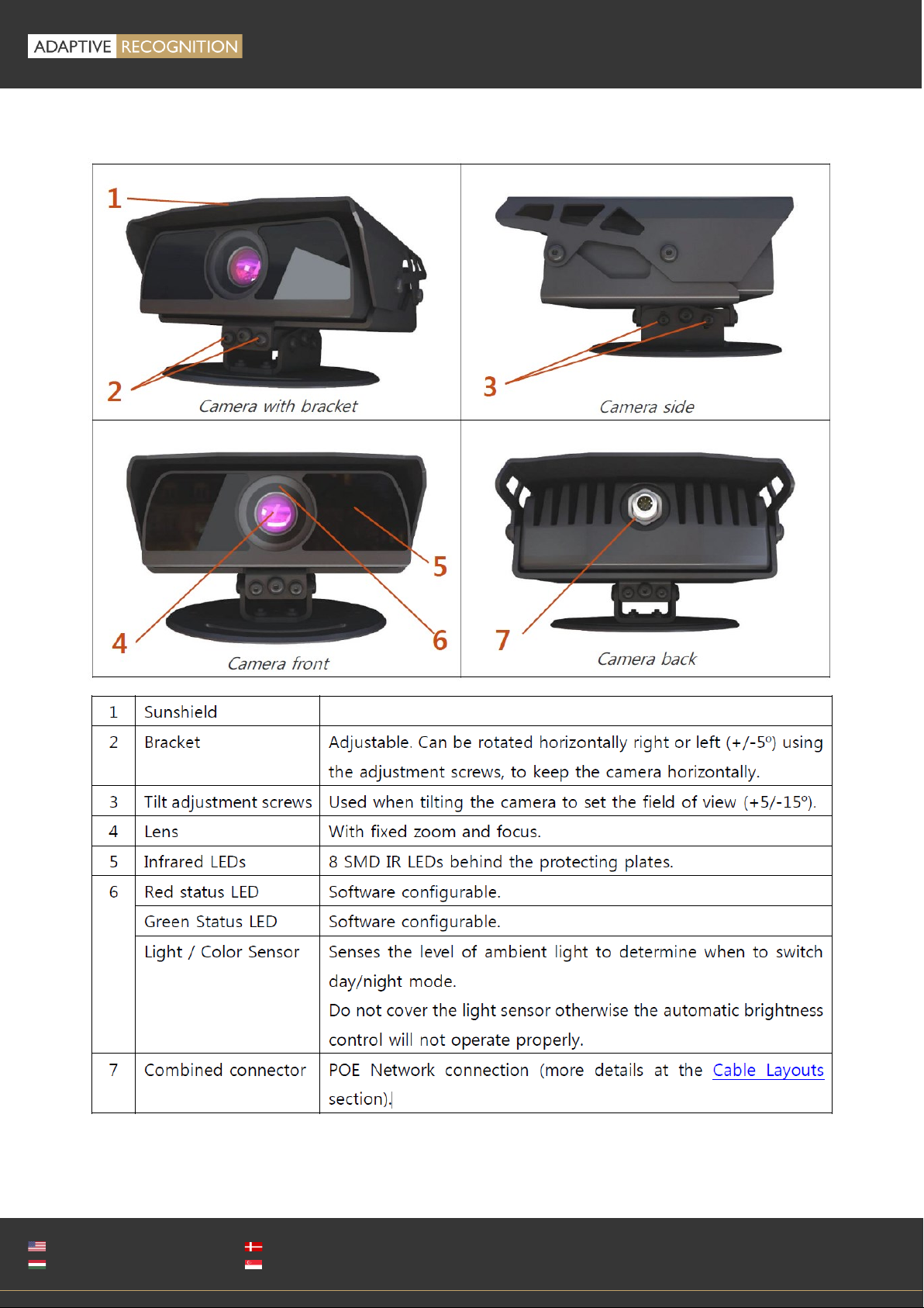
1. HARDWARE OVERVIEW

Page 5/21
MICROCAM Install Guide
Adaptive Recognition America
Adaptive Recognition Hungary
Adaptive Recognition Nordic
Adaptive Recognition Singapore
REQUESTINFO@ADAPTIVERECOGNITION.COM
WWW.ADAPTIVERECOGNITION.COM
1.1. BRACKET
Additional accessories and mounting accessories may be required depending on the actual
vehicle. See an extra bracket option below –contact your sales person for further details &
availability.
We do NOT recommend removing the camera shield in hot environments, as it protects the
device from direct sunlight exposure, which also helps with the unit's temperature
regulation.

Page 6/21
MICROCAM Install Guide
Adaptive Recognition America
Adaptive Recognition Hungary
Adaptive Recognition Nordic
Adaptive Recognition Singapore
REQUESTINFO@ADAPTIVERECOGNITION.COM
WWW.ADAPTIVERECOGNITION.COM
2. INSTALL THE HARDWARE
Adjust the bracket
1. Place the camera on the roof or trunk of the vehicle, gantry
or pole (in case of fixed installation), and slightly tighten the
bracket plate at the curve slots of the plate designed for this
purpose.
2. Adjust the bracket into the desired position.
Tighten the screw back.
3. It is recommended to secure the camera by a cable
(carabiner) to the roof of the vehicle or to the vehicle’s roof
rack.
2.1. MOUNTING
The bracket can be mounted into different surfaces. Use appropriate screws for installationaccording
to the mountable surface. By default, the camera is provided with a mobile (vehicle) bracket. By using
this bracket, the camera can be mounted on a vehicle roof rack or on a flat surface. As a safety
precaution, you may want to secure the camera with a cable or steel wire rope through the anchor
hole –in case the mount screws should, for any reason, let go. See camera side panel to find the
anchor hole as shown in the image (upper hole).
Remove protective film from the protecting plate (on the camera front) before using the
camera.
Do not overtighten the screws.
Additional accessories and mounting elements may be required depending on the actual
vehicle.
Secure mounting is the responsibility of the user.
Page 7/21
MICROCAM Install Guide
Adaptive Recognition America
Adaptive Recognition Hungary
Adaptive Recognition Nordic
Adaptive Recognition Singapore
REQUESTINFO@ADAPTIVERECOGNITION.COM
WWW.ADAPTIVERECOGNITION.COM
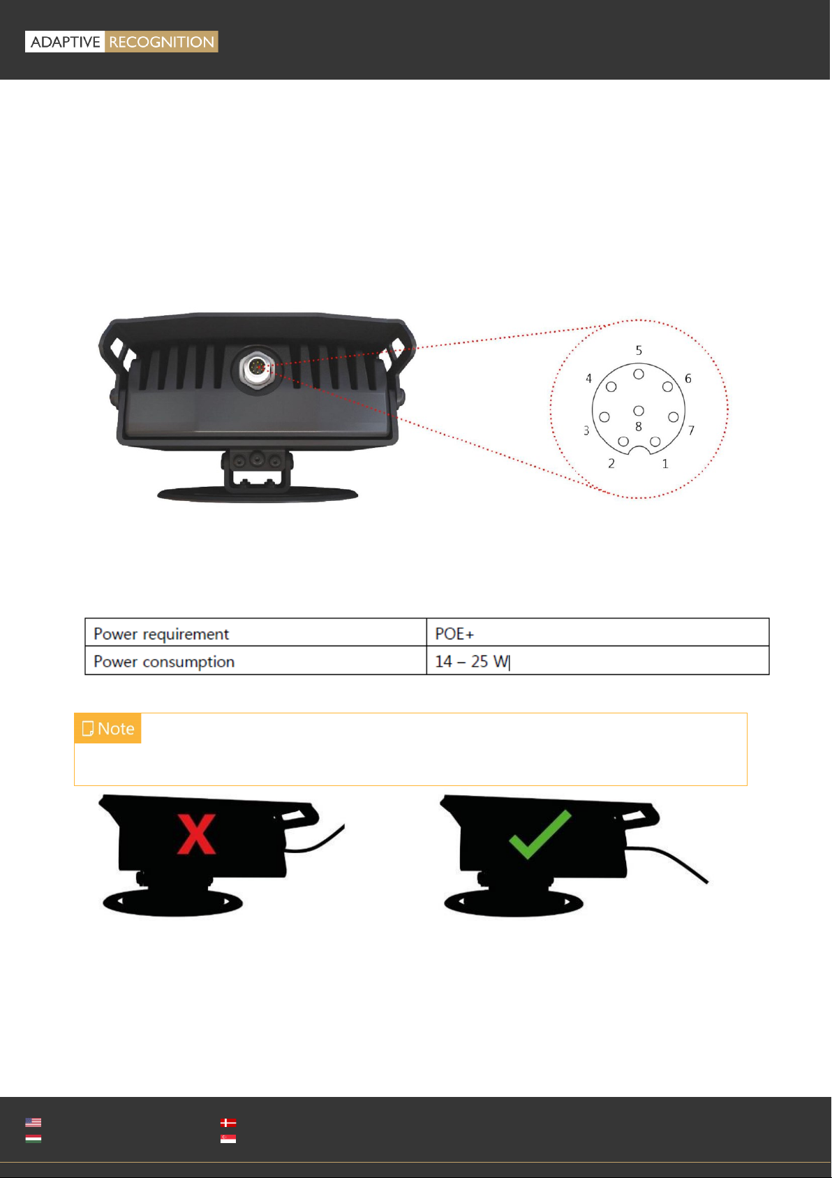
3. CONNECT THE CABLES
If the cable is plugged correctly to the connector of the camera, the fastening ring of the plug should
be turned clockwise to keep it tight and waterproof.
3.1. CABLE LAYOUTS
The unit comes with a 5-meter (16 feet) cable. First connect the cable to the camera and after that, to
the POE+ connector. The power supply must meet IEEE 802.3at POE+ standards.
POWER SPECIFICATIONS:
Please use the proper input according to the specification and consider the voltage drop factor.
Route the cable according to the image to avoid collecting rainwater at the socket.
Technical specifications are subject to change without prior notice.

Page 8/21
MICROCAM Install Guide
Adaptive Recognition America
Adaptive Recognition Hungary
Adaptive Recognition Nordic
Adaptive Recognition Singapore
REQUESTINFO@ADAPTIVERECOGNITION.COM
WWW.ADAPTIVERECOGNITION.COM
4. SOFTWARE REQUIREMENTS
The cameras are developed to operate without any kind of special software.
SOFTWARE REQUIREMENTS:
•For network setup, administrator (root) privileges are necessary.
•Web browser: Mozilla Firefox 52, Microsoft Edge, Google Chrome 51.X.X.X or later editions. If it is
possible, update your browser (Firefox or Chrome) to the newest available version.
5. ACCESSING THE CAMERA
Steps for accessing the camera’s web interface from a browser:
1. Connect the camera to a POE+ network switch. During the boot cycle the red status LED on the
camera front will turn on and the green status LED flashes twice. You might also notice the IR
illumination getting activated, and after successful booting each LED turns off signaling that the
camera is ready for operation.
Ensure that the computer you are connecting from is
within the same IP subnet as the camera. In case of first
connectionthe camera factory IP is 192.0.2.3, so be sure
to set your computer’s IP in the 192.0.2.x subnet – where
x is an integer number between 1 and 254 except 3 –
with the subnet mask of 255.255.255.0.
For more information, see Appendix.
2. Use the ping command to test the communication with the camera:
•Windows: C:\>ping -t 192.0.2.3
•Linux: username@mylinux:~$ ping 192.0.2.3
3. Soon, the ping package returns: Reply from 192.0.2.3.
a. Start a browser then enter the default IP address of the camera into the address bar
(http://192.0.2.3). After this, the camera starts in default administrator mode, ready to be set
up and configured.
b. If you cannot reach the device interface:
•first check the Ethernet LEDs at the PC or the switch side
•checkwhether the IP address is set correctly; or if you can ping the PC’s own IP address.
•check if proxy is set in the browser or that the browser is not set to offline.
If you can confirm that none of these issues apply but there is still no reply, power off then on and
enter the previous ping command again.
The firmware version of the camera can be seen on the right lower side of the screen. New
firmware versions are regularly released. If update is necessary, do not hesitate to contact
the support team of ARH.
To enable all camera functions, enable JavaScript control in your browser.

Page 9/21
MICROCAM Install Guide
Adaptive Recognition America
Adaptive Recognition Hungary
Adaptive Recognition Nordic
Adaptive Recognition Singapore
REQUESTINFO@ADAPTIVERECOGNITION.COM
WWW.ADAPTIVERECOGNITION.COM
6. RECOMMENDED CAMERA POSITION
After you have connected your computer directly or via switch to the camera, you should be able to
see the web interface in your browser (camera default IP is 192.0.2.3). You may now follow the steps
below to set your camera properly. This section intends to provide recommendations to achieve the
best setup for both vehicle mounted and fixed MicroCAM installations.
A good ANPR engine can read the plates from images taken in various conditions. However, if you
want to achieve over 95% recognition rate with short recognition times, you should carefully select
most ideal camera position.
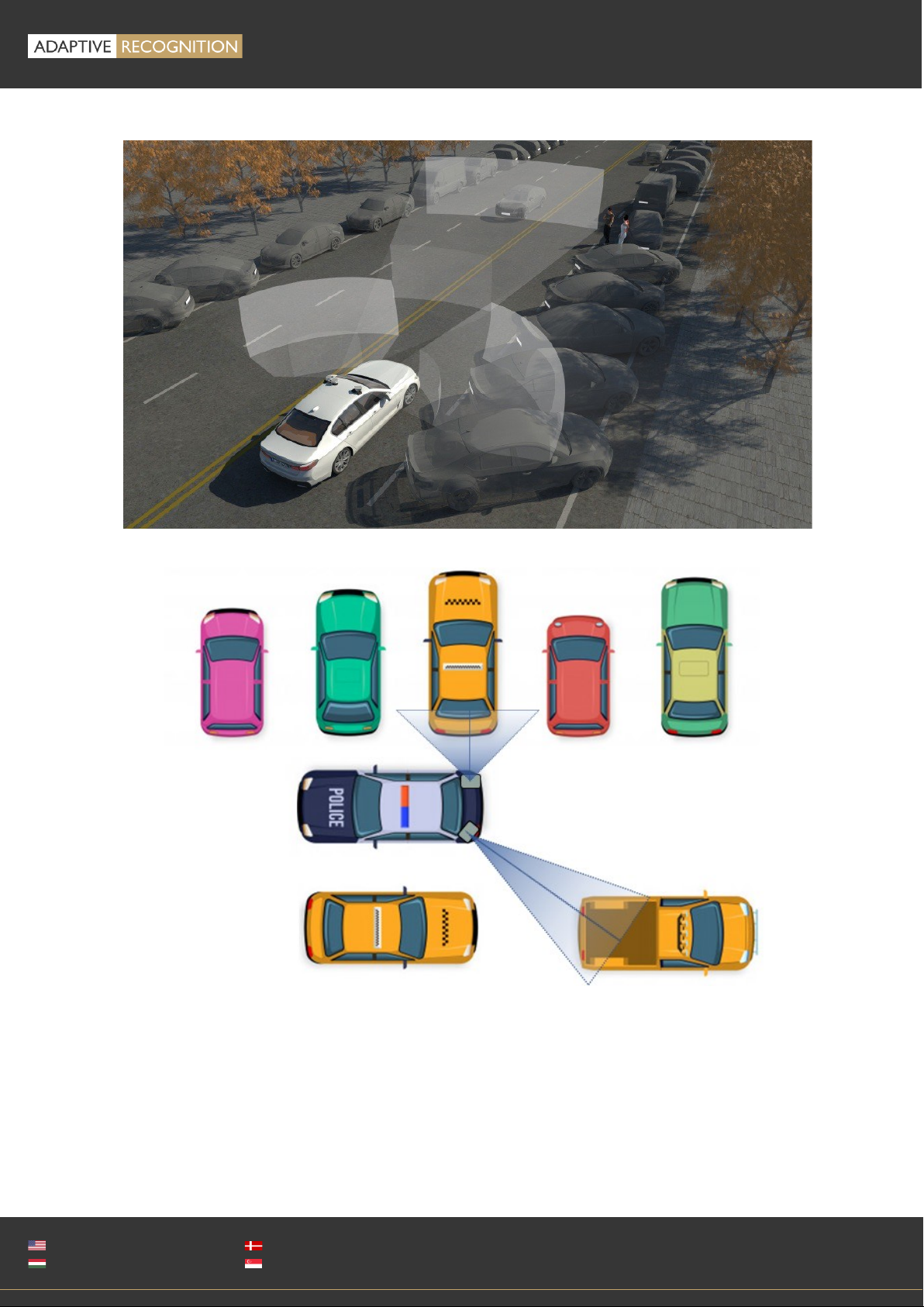
6.1. MOBILE DEPLOYMENTS
To use the M402 camera on your vehicle, it can be mounted in different ways depending upon the
purpose of the use case. A couple of common use cases (and installations) are as follows:
•Parking application (short-range lens): camera is turned 80°-90° from the longitudinal axis of the
car towards parked cars, and tilted down (max. 35°) to reduce background interference (e.g.
horizon, signs, fences).
•Traffic monitoring (long-range lens): camera is turned approx. 0°-25° from the longitudinal axis of
the car towards the monitored lane (left or right) and tilted down 5°-15°.
1.1.1. Parking application:
Ensure that you have mounted the camera in a way that allows target license plates of parked vehicles
to remain at approximately 1-2 meters / 3-7 feet from the device (if possible) as your vehicle patrols
the parking area, and that the camera’s view of the vehicles is not blocked. The most important factor
is to capture the vehicle plate and have a workable license plate size with characters around 25-80
pixels tall, as explained in the install guide.

Page 10/
21
MICROCAM Install Guide
Adaptive Recognition America
Adaptive Recognition Hungary
Adaptive Recognition Nordic
Adaptive Recognition Singapore
REQUESTINFO@ADAPTIVERECOGNITION.COM
WWW.ADAPTIVERECOGNITION.COM
Sample images:
In case of trunk or roof installation, the camera should provide similar images:
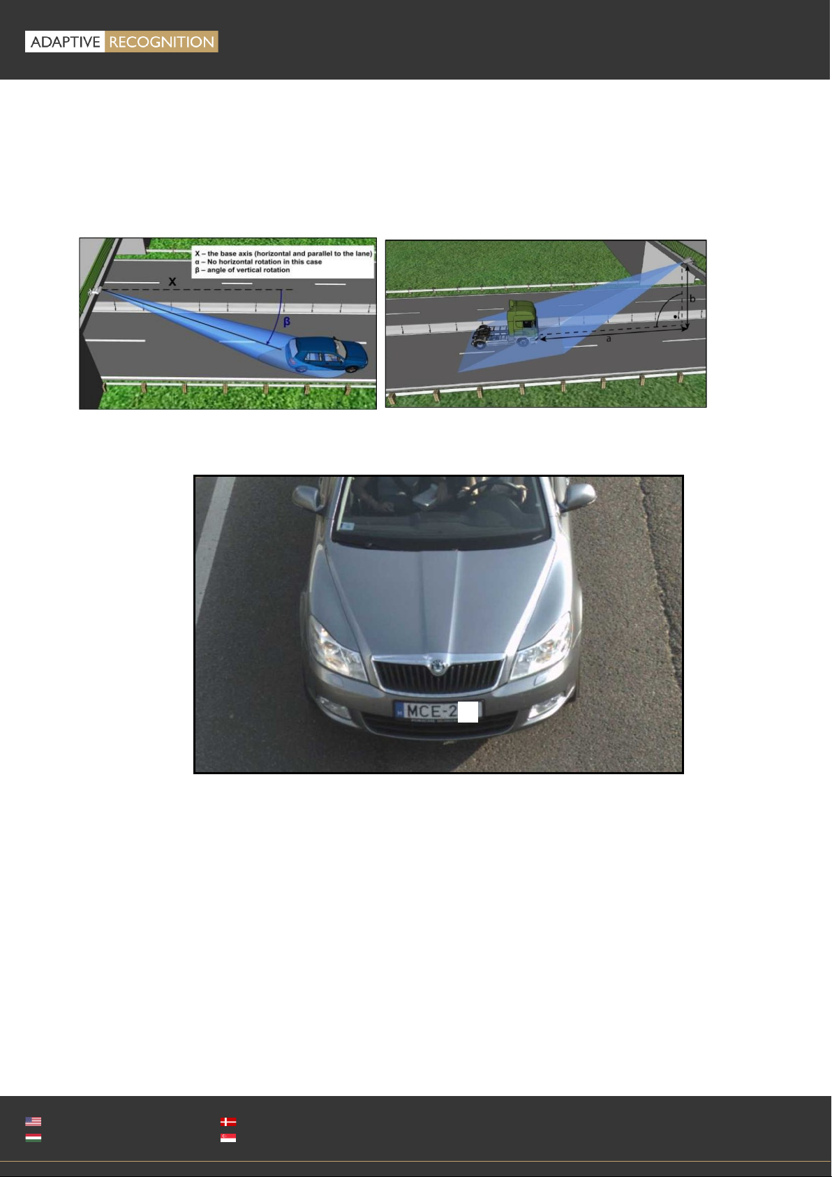
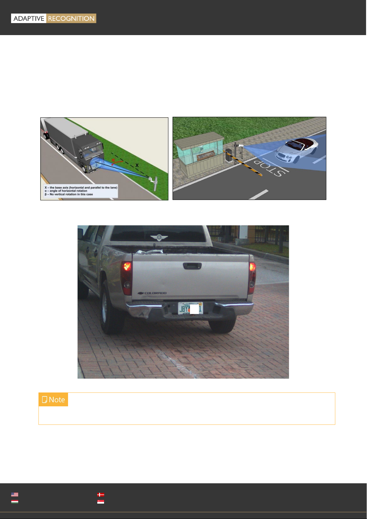
6.1.1. Traffic monitoring (often directed at oncoming traffic):
The camera should be mounted on the vehicle corresponding to the direction of the travel, or the
opposite, panned to the left or right (or centered) as appropriate (e.g. ~25°relative to the longitudinal
direction of the oncoming vehicles) and slightly tilted down (by ~8°relative to horizontal position).
Height of the vehicle rooftop may change the tilt angle (+8°difference).

Page 11/
21
MICROCAM Install Guide
Adaptive Recognition America
Adaptive Recognition Hungary
Adaptive Recognition Nordic
Adaptive Recognition Singapore
REQUESTINFO@ADAPTIVERECOGNITION.COM
WWW.ADAPTIVERECOGNITION.COM
Try to keep the license plate in a horizontal position in the live view (see below image).
The camera should provide similar images, depending on the angles
Page 12/
21
MICROCAM Install Guide
Adaptive Recognition America
Adaptive Recognition Hungary
Adaptive Recognition Nordic
Adaptive Recognition Singapore
REQUESTINFO@ADAPTIVERECOGNITION.COM
WWW.ADAPTIVERECOGNITION.COM
Example for dual camera setup:

Page 13/
21
MICROCAM Install Guide
Adaptive Recognition America
Adaptive Recognition Hungary
Adaptive Recognition Nordic
Adaptive Recognition Singapore
REQUESTINFO@ADAPTIVERECOGNITION.COM
WWW.ADAPTIVERECOGNITION.COM
6.2. FIXED POSITION DEPLOYMENTS
The best position is if the camera is installed on a gantry above the traffic lane (see below).
If there is no possibility to install a gantry above the concerned road section, the installation of the
camera can be done near the road. In this case the angle between the camera axis and the direction
of the vehicle movement should be minimal and the camera should be installed 1 –1,5 meters above
the headlights of the vehicles.
The distance between the camera and plate is also important. If the camera is too far from the plate,
the characters may not be large enough for recognition. If the distance is too short, it may happen
that a part of the plate is outside the camera’s field of view (when the vehicle is near the edge of the
lane or the plate is not at the middle of the vehicle). From an LPR software point of view, the most
important factor is the height of the characters on the image. For Latin characters it is recommended
to have at least 20 pixel average character height (optimal 30-40 pixel). Oversize characters are also
not suitable for LPR, therefore try toavoid settings where the character height is greater than 80pixels.
Also, the line width of a character on the image should be at least 2 pixels.
The recommended camera unit for fixed deployment is the Vidar camera family
Page 14/
21
MICROCAM Install Guide
Adaptive Recognition America
Adaptive Recognition Hungary
Adaptive Recognition Nordic
Adaptive Recognition Singapore
REQUESTINFO@ADAPTIVERECOGNITION.COM
WWW.ADAPTIVERECOGNITION.COM
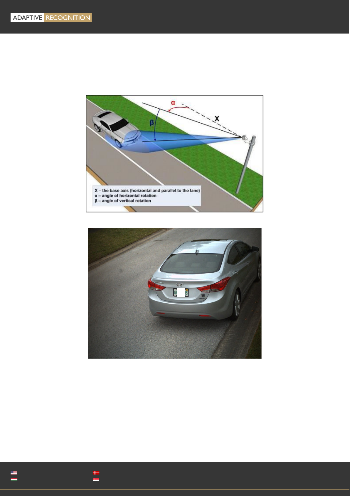
Overhead is when the device is installed above the lane (approx. 4-8 meters high) in the center (for
example on an overpass or gantry, etc.) tilted down, the vertical tilt (β) should be less than 35 degrees
(optimal 30 degrees) and the horizontal rotation should be 0 degrees.
Typical deployment: fixed installation on a highway or city monitoring from gantry, bridge or “L” type
pole.
A properly set camera should provide a similar image:
Page 15/
21
MICROCAM Install Guide
Adaptive Recognition America
Adaptive Recognition Hungary
Adaptive Recognition Nordic
Adaptive Recognition Singapore
REQUESTINFO@ADAPTIVERECOGNITION.COM
WWW.ADAPTIVERECOGNITION.COM
Lateral is when the device is placed near the traffic lane. We recommend no more than 1m distance
from the lane, and the angle ofhorizontal rotation () should be 25 degrees or less. The camera should
be a relatively low position (approx. 1-1,5 meters high or 1m + the level of the vehicle headlights in
case of front vehicle monitoring). The vertical rotation degree should be as low as possible.
Typical deployment: portable tripod installation on roadside, pole mount access controlor fromparked
vehicle.
A properly set camera should provide a similar image
The camera should be tilted down, and NOT monitor the horizon, or the sky.
Page 16/
21
MICROCAM Install Guide
Adaptive Recognition America
Adaptive Recognition Hungary
Adaptive Recognition Nordic
Adaptive Recognition Singapore
REQUESTINFO@ADAPTIVERECOGNITION.COM
WWW.ADAPTIVERECOGNITION.COM
Transversal is when the device is installed on a pole near the road. It should be pointed towards the
vehicles by panning and tilting (approx. placed at a distance of 1-2 meters from the road and 3-6
meters high).
Typical deployment: fixed installation on a road from pole for traffic counting, red-light enforcement
or city monitoring.
A properly set camera should provide a similar image

Page 17/
21
MICROCAM Install Guide
Adaptive Recognition America
Adaptive Recognition Hungary
Adaptive Recognition Nordic
Adaptive Recognition Singapore
REQUESTINFO@ADAPTIVERECOGNITION.COM
WWW.ADAPTIVERECOGNITION.COM
7. APPENDIX
7.1. ADDING ALTERNATE IP ADDRESS
Windows
1. Click Start and select Control Panel.
2. Open Network and Sharing Center.
3. Click Manage Network Connections on the left side of
Network and Sharing Center.
4. Click on the network connection you want to add an IP
address for (to which the camera has been connected)
and select Properties.
5. Select Internet Protocol Version 4(TCP/IPv4), click on
Properties and select the Alternate Configuration tab.
6. Select User configured and enter e.g. the 192.0.2.54 IP
address and 255.255.255.0 as Subnet mask as shown on
the right side screenshot sample.
7. Click OK in the opened windows.
Linux
1. Open a terminal.
2. Enter the ifconfig command to see the reserved Ethernets (e.g. eth0).
3. Enter the following command: ifconfig ethY192.0.2.25
where Yis a free eth (e.g. eth1) and 192.0.2.25 is a sample IP address.
7.2. INFRARED (IR) CAUTION
The device is equipped with an 850nm (or 760nm) wavelength infrared LED
illumination, which is barely or not at all visible to the human eye. Do not look
directly into the IR emitters from a close range or for more than 100 seconds.
Eye damage may occur if these precautions are not taken.
Page 18/
21
MICROCAM Install Guide
Adaptive Recognition America
Adaptive Recognition Hungary
Adaptive Recognition Nordic
Adaptive Recognition Singapore
REQUESTINFO@ADAPTIVERECOGNITION.COM
WWW.ADAPTIVERECOGNITION.COM
7.3. UNIT SERIAL NUMBER
There is a sticker on the bottom of the unit, indicating the Model, IP address, MAC address and the
Serial Number of the camera.
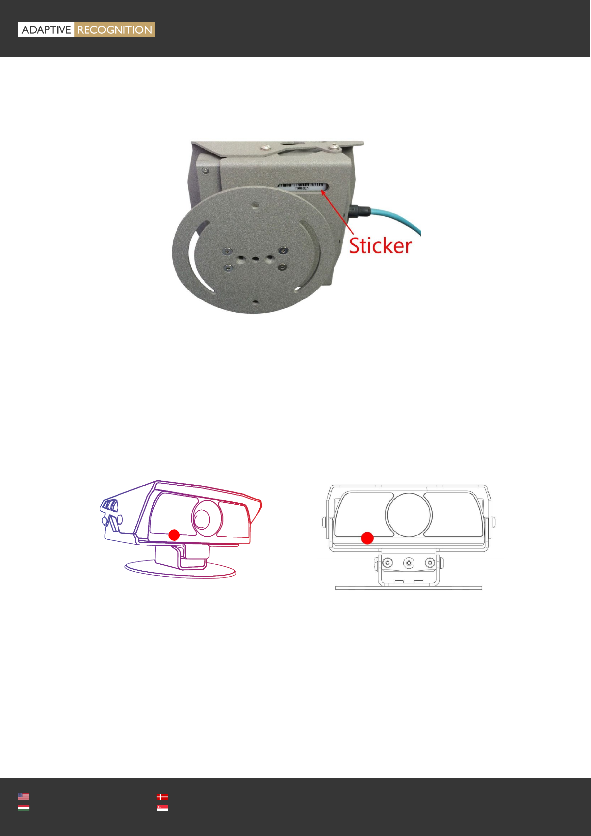
7.4. RECOVERY MODE
You can put the device in recovery mode in two different ways.
-Select RECOVERY MODE under the MAINTENANCE section on the camera interface
-If the web interface is not reachable (for example unknown IP address), you can use the magnetic
reset procedure. The recommended strength of the magnet is 1210 mT (millitesla). Not included
in the camera package and not supplied by Adaptive Recognition. Steps:
1. Start by powering OFF the device.
2. Place a magnet to the indicated position (red spot below)
3. Power on the device by plug into a POE+ connector (if the magnet is in proper position, the
green indicator led on the front of the camera will start flashing)
4. Wait 10 seconds and then remove the magnet
5. Enter the default 192.0.2.3 IP address in a connected browser

Page 19/
21
MICROCAM Install Guide
Adaptive Recognition America
Adaptive Recognition Hungary
Adaptive Recognition Nordic
Adaptive Recognition Singapore
REQUESTINFO@ADAPTIVERECOGNITION.COM
WWW.ADAPTIVERECOGNITION.COM
7.5. MODEL VERSIONS
MicroCAM is available in four different versions. You can choose
between two lens options –a long- and a short-range (wide) –and
with or without on-board ANPR / LPR.
Without on-board ANPR\LPR
With on-board ANPR/LPR
Wide (short-range optics)
M202 Wide
M402 Wide
Long range optics
M202
M402
7.5.1. SHORT-RANGE MICROCAMS
(M202 Wide and M402 Wide)
These cameras are designed mostly for urban
deployments; traffic situations involving slower
moving traffic, such as monitoring parked vehicles.
These cameras are typically mounted on the roof or
trunk of the patrolling vehicle turned 75-90° to the
side, tilted down slightly. Wide angle lens MicroCAM
models have an LPR range of 1-3 meters and a 76°
angle of view.
7.5.2. LONG-RANGE MICROCAMS
(M202 and M402)
The long-range cameras’main purpose is to
monitor traffic adjacent lanes in any direction, often
at high speeds. These cameras are typically
mounted on the roof or trunk of the patrolling
vehicle turned 0-25° to the side, tilted down slightly.
Long-range MicroCAM models have an LPR range
of 4-10 meters with an angle of view of 25°.
7.5.3. MIXED CAMERAS USED
Sometimes multiple cameras are required to capture
the highest number of license plates since not every
US state requires front and back license plates. In
addition to this, you can combine short and long range
units to increase capture rate.
Page 20/
21
MICROCAM Install Guide
Adaptive Recognition America
Adaptive Recognition Hungary
Adaptive Recognition Nordic
Adaptive Recognition Singapore
REQUESTINFO@ADAPTIVERECOGNITION.COM
WWW.ADAPTIVERECOGNITION.COM
7.5.4. ONBOARD ANPR/LPR OPTIONS
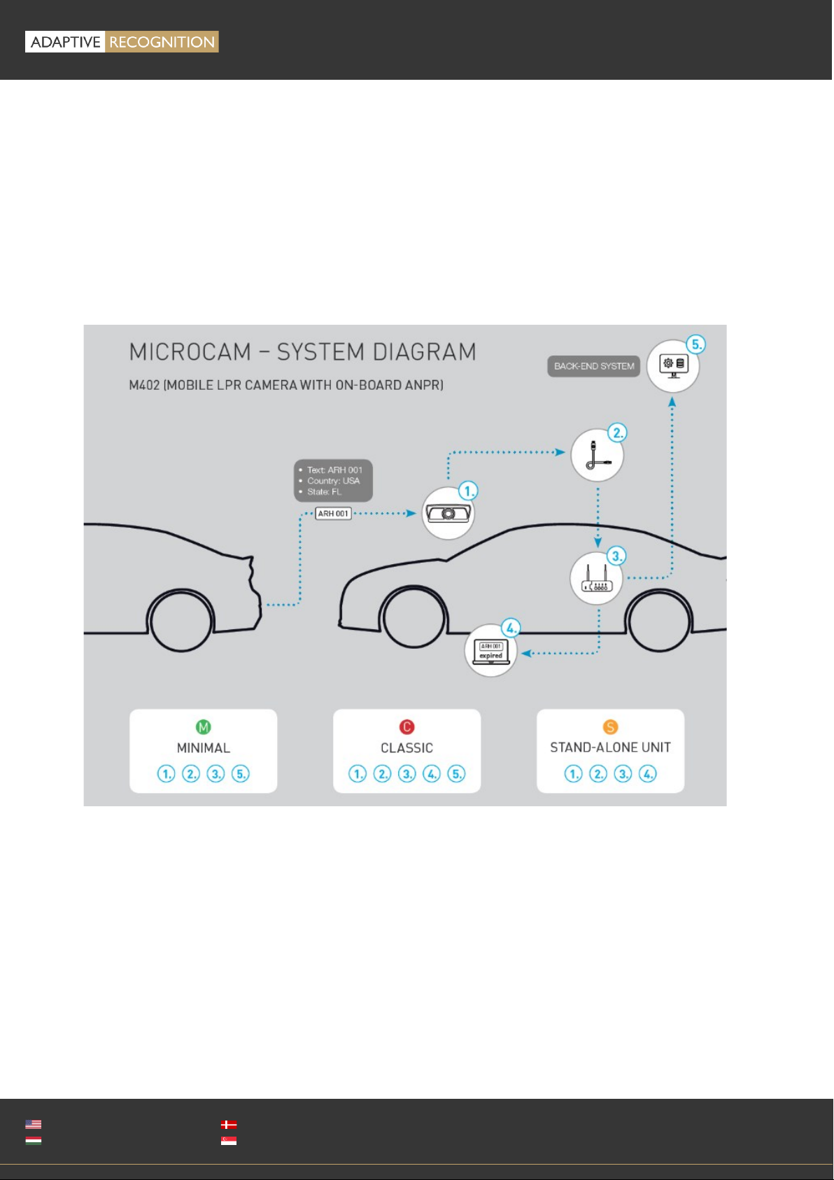
Adaptive Recognition offers two different MicroCAMs for two different system architectures. The
M402 ANPR/LPR camera provides on-board ANPR/LPR which keeps the system light-weight and
incredibly easy to integrate. However, the limited onboard processing capacity of edge-processing
units does not offer the highest detection rates. M202 cameras deployed with separate Carmen LPR
software modules may reach higher detection and recognition rates.
7.5.5. TYPICAL SYSTEM STRUCTURES
Table of contents
Popular Automobile Accessories manuals by other brands

Schartec
Schartec CR4 quick start guide

Tesla
Tesla Model S Roof Rack owner's manual

Curt Manufacturing
Curt Manufacturing 16050 installation manual

Dynojet
Dynojet Power commander V installation instructions

Fiamma
Fiamma CARRY-BIKE MERCEDES VITO Installation and usage instructions

Prorack
Prorack K470 Fitting instructions

injen technology
injen technology EVO1107 installation instructions

Evolve
Evolve TRED Instructions for use

Advent
Advent TOYBTSW3 owner's manual

Metra Electronics
Metra Electronics 99-3411 installation instructions

DIGITAL DELAY
DIGITAL DELAY 1025 quick start guide

Bully
Bully PL-807 installation instructions


