Adaptive P1507 User manual

28x96 Front Access Full Matrix LED Sign
Maintenance Manual
1.07-inch, 1.35-inch, and 1.75-inch Pitch Signs with 2 Controllers
P1507/P1514
Manual part number: 1507610501 rev. A
Revision date: December 10, 2007

© Copyright 2007 Adaptive Micro Systems LLC. All rights reserved.
Adaptive Micro Systems
7840 North 86th Street
Milwaukee, WI 53224 USA
414-357-2020
414-357-2029 (fax)
http://www.adaptivedisplays.com
Adaptive is a regisered trademark of Adaptive Micro Systems. All other brand and product names are
trademarks or registered trademarks of their respective companies.

March 2, 2006 Front Access Full Matrix LED Sign Maintenance Manual (pn 1507610501 rev. A)
Front Access Full Matrix LED Sign Maintenance Manual (pn 1507610501 rev. A) 3
Contents
Introduction............................................................................ 7
Purpose ..................................................................................................................................................... 7
Revision history......................................................................................................................................... 7
Related documentation.............................................................................................................................. 7
Safety information ..................................................................................................................................... 7
Battery backup........................................................................................................................................... 8
System overview ..................................................................... 9
Introduction............................................................................................................................................... 9
VMS control system .................................................................................................................................. 9
LED brightness control system................................................................................................................ 10
Environmental control system — sign housing....................................................................................... 10
Electrical system...................................................................................................................................... 10
Equipment description..............................................................13
General description.................................................................................................................................. 13
Outside views — 1.07-inch pitch sign..................................................................................................... 14
Outside views — 1.35-inch pitch sign..................................................................................................... 15
Outside views — 1.75-inch pitch sign..................................................................................................... 16
Inside view — 1.07-inch pitch sign ......................................................................................................... 17
Inside view — 1.35-inch pitch sign ......................................................................................................... 18
Inside view — 1.75-inch pitch sign ......................................................................................................... 19
Controller plate ....................................................................................................................................... 20
Sign controllers #1 and #2....................................................................................................................... 21
Sign power panels ................................................................................................................................... 23
LED driver board...................................................................................................................................... 24
Maintenance .........................................................................25
Physical Inspection.................................................................................................................................. 25
Front lens cleaning................................................................................................................................... 25
Air filter cleaning...................................................................................................................................... 26

AlphaXpress DMS Sign (Texas DOT) Maintenance Manual (pn 1509620301) March 2, 2006
4Front Access Full Matrix LED Sign Maintenance Manual (pn 1507610501 rev. A)
Part replacement ....................................................................27
List of field-replaceable parts................................................................................................................... 27
Controlling electrostatic discharge (ESD) ................................................................................................ 27
Opening a sign......................................................................................................................................... 28
Sign controller board replacement........................................................................................................... 32
Power supply replacement....................................................................................................................... 35
Diode module replacement ...................................................................................................................... 37
Relay replacement ................................................................................................................................... 39
LED driver board replacement ................................................................................................................. 41
Fan replacement ...................................................................................................................................... 42
Heater replacement.................................................................................................................................. 43

Front Access Full Matrix LED Sign Maintenance Manual (pn 1507610501 rev. A) 5
List of figures
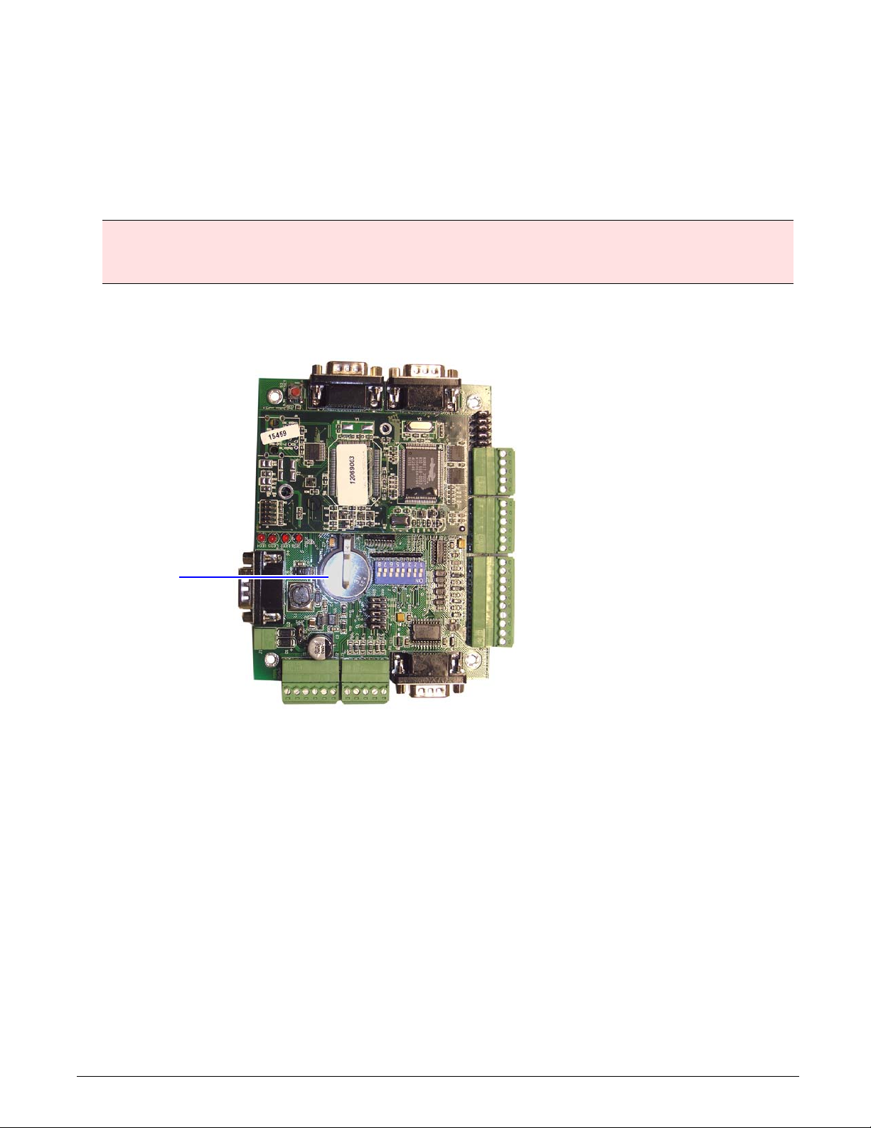
Figure 1: Location of the 3V lithium battery on the sign’s controller, page 8
Figure 2: 5x7 font dimensions, page 13
Figure 3: LED pitch, page 13
Figure 4: Exterior top, front, bottom, back, and side views of a 1.07-inch sign, page 14
Figure 5: Exterior top, front, bottom, back, and side views of a 1.35-inch sign, page 15
Figure 6: Exterior top, front, bottom, back, and side views of a 1.75-inch sign, page 16
Figure 7: Internal components of a 1.07-inch sign, page 17
Figure 8: Internal components of a 1.35-inch sign, page 18
Figure 9: Internal components of a 1.35-inch sign, page 19
Figure 10:Controller plate components, page 20
Figure 11:Sign controller components, page 21
Figure 12:Power panel components, page 23
Figure 13:LED driver board views and components, page 24
Figure 14:Air filter locations in the 1.75-inch pitch sign.The 1.07-inch and 1.35-inch pitch signs have 4 fans, see “In-
ternal view — 1.07-inch pitch sign” on page 17 or “Internal view — 1.35-inch pitch sign” on page 18 for
locations, page 26
Figure 15:Door latch locations on 1.07-inch and 1.35-inch pitch signs, page 28
Figure 16:Front face frame and prop rod, page 28
Figure 17:Fastening LED panels, page 28
Figure 18:Removing quick release pin and unfastening LED panels, page 29
Figure 19:Door latch locations on the 1.75-inch pitch sign, page 29
Figure 20:Loosening the seal, page 29
Figure 21:Turning the winch handle, page 30
Figure 22:Lift arms and door support arms on the 1.75-inch pitch sign, page 30
Figure 23:Disengaging the door’s support arms, page 31
Figure 24:Cranking the door closed, page 31
Figure 25:Push the door completely closed, page 31
Figure 26:Controller jumper locations and dip switch settings, page 32
Figure 27:Controller board screws and jumpers, page 33
Figure 28:Settings in the IP Set Utility, page 34
Figure 29:Power supply wiring, page 35
Figure 30:Screw locations on the power supply, page 36
Figure 31:Nuts securing the diode module to the power plate, page 37
Figure 32:Diode module connections, page 38
Figure 33:Relay locations, page 39

6Front Access Full Matrix LED Sign Maintenance Manual (pn 1507610501 rev. A)
Figure 34:Relay, page 40
Figure 35:Example of a 1.07-inch/1.35-inch pitch sign. The larger 1.75-inch pitch signs have lift arms and winch
handles, page 41
Figure 36:Fan locations, page 42
Figure 37:Screws securing the fan panel housing, page 42
Figure 38:Locations of the 6-32 nuts on the fan guard, page 42

Introduction December 10, 2007
Front Access Full Matrix LED Sign Maintenance Manual (pn 1507610501 rev. A) 7
Introduction
Purpose
This manual is intended as a guide for maintenance and repairs considered field serviceable.
This field service manual supplies technical information for service and technical personnel so that they can
maintain the equipment at the assembly but not the component level.
Revision history
Related documentation
Technical documentation can be found at Adaptive’s Web site (http://www.adaptivedisplays.com).
Safety information
Equipment symbols
Warnings and cautions
Warnings and cautions are posted in appropriate locations throughout this manual.
Revision Date Notes
1507610501 rev. A December 10, 2007 Initial release.
Part # Manual title Description
1507650207 Wiring Diagram Sign wiring diagram for the 1.07-inch pitch sign
with two controllers.
1507650201 Wiring Diagram Sign wiring diagram for the 1.35-inch pitch sign
with two controllers.
1507650202 Wiring Diagram Sign wiring diagram for the 1.75-inch pitch sign
with two controllers.
TechMemo #00-0005 Preventing Electrostatic Discharge
(ESD) Damage
Describes the precautions to take to protect
electronic components from ESD damage.
Chassis ground

Introduction P1509 21 x 125 Line Matrix
8Front Access Full Matrix LED Sign Maintenance Manual (pn 1507610501 rev. A)
Battery backup
In the event of power loss, a lithium battery provides power to the sign’s controller boards.
Note:
The backup battery provides only enough power to back up the sign controller’s memory, not the sign’s
LED displays.
3V lithium backup battery
One 3V lithium battery is located on each of the sign’s controller boards.
Figure 1. Location of the 3V lithium battery on the sign’s controller.
WARNING! Danger of explosion if battery is incorrectly replaced. Replace only with the same or
equivalent type recommended by the manufacturer. Dispose of used batteries according to the
manufacturer’s instructions.
3V lithium battery
(Panasonic CR2032 or
equivalent)

System overview December 10, 2007
Front Access Full Matrix LED Sign Maintenance Manual (pn 1507610501 rev. A) 9
System overview
This section contains the LED Variable Message Sign (VMS) systems description and a general explanation of
how each system operates.
Introduction
The Adaptive LED family of Variable Message Signs is considered to be one of the highest visibility sign
systems available. Utilizing the latest generation of light emitting diode (LED) technology has allowed us to
construct a high-reliability, variable message sign display system.
The LED Variable Message Signs discussed in this manual consist of front access types with a 28 x 96 display
board at 1.07-inch, 1.35-inch, and 1.75-inch pitch. The signs are designed for use as outdoor highway
information signs. The signs utilize a corrosion-resistant front access housing with enclosed control circuitry
within. The only connections necessary are AC power and Communications Input/Output between the sign
housings and the ground cabinets.
General system
The entire sign system can be broken down into four basic subsystems:
• VMS control system
• LED brightness control system
• Environmental control
• Electrical system
In the following sections, we explain each of the above-mentioned systems in general terms for ease of
understanding. Referring to the drawings throughout this manual should help you to gain a general
understanding of the LED Variable Message Sign system.
What is an LED?
LED-based signs are one of the most versatile and visible display systems available. We use a cluster of four
LEDs to form a single pixel. The pixels are arranged in various matrices to form alphanumeric characters.
These characters are then linked together to form an LED display line. The display line format used in the signs
discussed in this manual is full matrix, which allows for the display of any alphanumeric character, including
punctuation marks, as well as simple graphics characters.
VMS control system
The VMS control system utilized in the Variable Message Sign consists of the following components:
• IDI 1320 controller
• IDI 1321 controller
• LED display board/driver board
General operation
The controllers interface with the “Host” computer system, and communicate with the Host through a CAT5
Ethernet cable or an RS232 Input/Output (I/O) port. Using this network connection or I/O port, the host issues
commands to, and requests status information from, the LED VMS equipment. The controllers monitor and
control the entire LED VMS system. Communication by the controllers to and from the host and the VMS is
accomplished using industry standard 10/100 Ethernet or RS232 communications circuitry and NTCIP
protocol.

System overview P1509 21 x 125 Line Matrix
10 Front Access Full Matrix LED Sign Maintenance Manual (pn 1507610501 rev. A)
LED brightness control system
The VMS is equipped with a brightness control system for the LEDs. The brightness control system ensures
that the display is readable in all lighting conditions.
The main components of the brightness control system are the following:
• Photocell assembly
• Photocells (3: 1 upper, 1 front of sign, and 1 back of sign)
• IDI 1320 Controller
General operation
The photocells are enclosed in the cabinet to protect them from the environment. The photocells continuously
monitor the ambient light conditions and send the information directly to the controller. The controller assembly
determines exactly how much ambient light is present through the light-sensing photocells and sends the
proper command to the display module for it to adjust duty cycle of the LED current drive, thus dimming or
brightening the LED modules according to the ambient light. (If the on time of the duty cycle is 50%, then the
brightness will be at 50%; if the on time of the duty cycle is 75%, then the brightness will be at 75%, etc.)
Environmental control system — sign housing
The environmental control system in the sign housing is responsible for maintaining a working environment for
the sign display components and communication electronics in the sign display systems. The environmental
control system consists of the following components:
• Photo/temperature sensor
•Fans
• Fan filters
•Fanrelay
• Humidity sensor
• Fan monitor board
• Heater strip
• Heater relay
General operation
The fans are responsible for exchanging air in the sign for temperature control and ventilation through the sign.
The fans are automatically turned OFF or ON based on the readings from temperature sensors and sign
controller settings. The fan monitor board is used to determine if the fans are operating within specifications
and communicates the fan status to the controller. The humidity sensor, heater strip, fans, and temperature
sensors are all used to determine if there is an environmental condition that could cause the front plex to fog.
Based on an algorithm, if the situation dictates it is needed, the heater strip will be enabled and the fans will
blow hot air across the front face. The fans automatically turn on when the temperature exceeds 120°F (50°C)
and automatically turn off when the temperature goes below 113°F (45°C).
Electrical system
The electrical supply system is responsible for supplying the necessary power to operate the LED sign system.
The sign housing AC and DC electrical system consists of the following components:
• Load center
• GFCI service outlet
• DC power supply

System overview December 10, 2007
Front Access Full Matrix LED Sign Maintenance Manual (pn 1507610501 rev. A) 11
Electrical distribution (AC)
The AC input to the sign systems consists of 120VAC single-phase service wired to the load center located in
the sign. AC is also wired to the DC power supplies. The signs discussed in this manual require 15A service for
the 1.07-inch and 1.35-inch pitch signs and 20A service for the 1.75-inch pitch sign.
Electrical distribution (DC)
Attached to the back panels in the sign housing are the power supply boxes that contain two 12VDC switching
power supplies. The electronic power supplies convert the 120VAC to the required DC voltage to power all of
the electronics in the sign. DC power to the electronics is redundant and has a primary and secondary source
of DC power. Therefore, failure of a power supply will not impact sign performance. The controller monitors the
status of the power supplies.

Introduction
12 Front Access Full Matrix LED Sign Maintenance Manual (pn 1507610501 rev. A)
THIS PAGE INTENTIONALLY BLANK

Equipment description December 10, 2007
Front Access Full Matrix LED Sign Maintenance Manual (pn 1507610501 rev. A) 13
Equipment description
General description
• Serviceability: Front access.
• Dimensions: Refer to the appropriate sign wiring diagram (see “Related documentation” on page 7).
• Weight (approximate): 1.07-inch pitch – 500 lbs, 1.35-inch pitch – 525 lbs, 1.75-inch pitch – 615 lbs.
• Electrical: 120VAC, 50/60Hz, 15A for the 1.07-inch and 1.35-inch pitch signs and 20A for the 1.75-inch
pitch sign. Typical current draw is approximately 5-8A.
• Display: Full matrix 28 x 96 pixels.
Figure 2. 5x7 font dimensions
• Pitch (distance between each LED pixel): 1.07-inch, 1.35-inch, and 1.75-inch pitch.
Figure 3. LED pitch
(5x7 Font)
Character width (nominal)
1.07-inch pitch = 6”
1.35-inch pitch = 7”
1.75-inch pitch = 9”
(5x7 Font)
Character height (nominal)
1.07-inch pitch = 8”
1.35-inch pitch = 10”
1.75-inch pitch = 12”
LED pixel
composed of four
individual LED
lamps
Pitch of LED pixel
• 1.07 inches
• 1.35 inches
• 1.75 inches Pitch
Pitch

Equipment description P1509 21 x 125 Line Matrix
14 Front Access Full Matrix LED Sign Maintenance Manual (pn 1507610501 rev. A)
Outside views — 1.07-inch pitch sign
Figure 4. Exterior top, front, bottom, back, and side views of a 1.07-inch sign
Item Name Description
AUPPER PHOTO CELL Used for controlling LED brightness.
BLIFTING EYEBOLTS Used to lift sign. These should NOT be used to mount the sign.
CFRONT PHOTO CELL Used for controlling LED brightness.
DLEDS Used to display messages.
EFRONT FACE FRAME LATCH Used to fasten sign front face frame.
FDRAIN HOLE Allows water that may accumulate inside the sign to escape.
GEXHAUST VENT OUTLET (WITH
HOOD)
Permits hot air from inside sign to exit.
HBACK PHOTO CELL Used for controlling LED brightness.
IINTAKE AIR VENT Allows cool air inside sign.
A
Top view
Front view
Bottom view
Back view
Side view
B
C
E
H
F
G
D
I

Equipment description December 10, 2007
Front Access Full Matrix LED Sign Maintenance Manual (pn 1507610501 rev. A) 15
Outside views — 1.35-inch pitch sign
Figure 5. Exterior top, front, bottom, back, and side views of a 1.35-inch sign
Item Name Description
AUPPER PHOTO CELL Used for controlling LED brightness.
BLIFTING EYEBOLTS Used to lift sign. These should NOT be used to mount the sign.
CFRONT PHOTO CELL Used for controlling LED brightness.
DLEDS Used to display messages.
EFRONT FACE FRAME LATCH Used to fasten sign front face frame.
FDRAIN HOLE Allows water that may accumulate inside the sign to escape.
GEXHAUST VENT OUTLET (WITH
HOOD)
Permits hot air from inside sign to exit.
HBACK PHOTO CELL Used for controlling LED brightness.
IINTAKE AIR VENT Allows cool air inside sign.
A
Top view
Front view
Bottom view
Back view
Side view
B
C
E
H
F
G
D
I

Equipment description P1509 21 x 125 Line Matrix
16 Front Access Full Matrix LED Sign Maintenance Manual (pn 1507610501 rev. A)
Outside views — 1.75-inch pitch sign
Figure 6. Exterior top, front, bottom, back, and side views of a 1.75-inch sign
Item Name Description
AUPPER PHOTO CELL Used for controlling LED brightness.
BLIFTING EYEBOLTS Used to lift sign. These should NOT be used to mount the sign.
CFRONT PHOTO CELL Used for controlling LED brightness.
DLEDS Used to display messages.
EFRONT FACE FRAME LATCH Used to fasten sign front face frame.
FDRAIN HOLE Allows water that may accumulate inside the sign to escape.
GEXHAUST VENT OUTLET (WITH HOOD) Permits hot air from inside sign to exit.
HBACK PHOTO CELL Used for controlling LED brightness.
IINTAKE AIR VENT Allows cool air inside sign.
JHANDLE Used to assist with opening the sign. See “Opening a sign” on page 28.
Back view
Bottom view
Front view
A
Top view
Side view
B
C
E
H
F
G
D
I
J

Equipment description December 10, 2007
Front Access Full Matrix LED Sign Maintenance Manual (pn 1507610501 rev. A) 17
Inside view — 1.07-inch pitch sign
Figure 7. Internal components of a 1.07-inch sign
Item Name Description
ACONTROLLER PLATE Mounting sub plate for controllers, outlet, fan monitoring board, and fan/heater control
relays.
BINTAKE FAN (FAN #4) Draws in air from outside.
CHEATER #2 Used to control humidity inside sign.
DAIR FILTER COVER When removed provides access to fan air filters.
ELOAD CENTER Principal AC power for sign. 120VAC 20A service required.
FPOWER PANEL #3 Convert AC power from load center to DC power.
GPOWER PANEL #2
HPOWER PANEL #1
IHEATER #1 Used to control humidity inside sign.
JINTAKE FAN (FAN #1) Draws in air from outside.
KLIGHT SENSOR #0 — FRONT The address number of a light sensor is set via SW1 and is the same as the light
sensor number. To replace light sensor board, remove the four nuts attached to the
mounting plate.
LLIGHT SENSOR #1 — TOP
MLIGHT SENSOR #2 — BACK
NEXHAUST VENT (FAN #2) Vents hot air inside the sign to the outside.
OEXHAUST VENT (FAN #3)
PLIGHT Automatically turns on when front is opened.
A
B
DFEGH C
M
I
NO
J
K
LDD P

Equipment description P1509 21 x 125 Line Matrix
18 Front Access Full Matrix LED Sign Maintenance Manual (pn 1507610501 rev. A)
Inside view — 1.35-inch pitch sign
Figure 8. Internal components of a 1.35-inch sign
Item Name Description
AINTAKE FAN (FAN #4) Draws in air from outside.
BHEATER #2 Used to control humidity inside sign.
CAIR FILTER COVER When removed provides access to fan air filters.
DCONTROLLER PLATE Mounting sub plate for controllers, outlet, fan monitoring board, and fan/heater control
relays.
EPOWER PANEL #3 Convert AC power from load center to DC power.
FPOWER PANEL #2
GPOWER PANEL #1
HHEATER #1 Used to control humidity inside sign.
IINTAKE FAN (FAN #1) Draws in air from outside.
JLIGHT SENSOR #0 — FRONT The address number of a light sensor is set via SW1 and is the same as the light
sensor number. To replace light sensor board, remove the four nuts attached to the
mounting plate.
KLIGHT SENSOR #1 — TOP
LLIGHT SENSOR #2 — BACK
MEXHAUST VENT (FAN #2) Vents hot air inside the sign to the outside.
NEXHAUST VENT (FAN #3)
OLOAD CENTER Principal AC power for sign. 120VAC 15A service required.
A
B
D
FE
G
H
CC
MCC
I
NO
J
KL

Equipment description December 10, 2007
Front Access Full Matrix LED Sign Maintenance Manual (pn 1507610501 rev. A) 19
Inside view — 1.75-inch pitch sign
Figure 9. Internal components of a 1.75-inch sign
Item Name Description
AINTAKE FAN (FAN #8) Draws in air from outside.
BHEATER #4 Used to control humidity inside sign.
CAIR FILTER COVER When removed provides access to fan air filters.
DCONTROLLER PLATE Mounting sub plate for controllers, outlet, fan monitoring board, and fan/heater control
relays.
ELOAD CENTER Principal AC power for sign. 120VAC 20A service required.
FPOWER PANEL #3 Convert AC power from load center to DC power.
GPOWER PANEL #2
HPOWER PANEL #1
IHEATER #3 Used to control humidity inside sign.
JHEATER #2
KHEATER #1
LINTAKE FAN (FAN #1) Draws in air from outside.
MLIGHT SENSOR #0 The address number of a light sensor is set via SW1 and is the same as the light
sensor number. To replace light sensor board, remove the four nuts attached to the
mounting plate.
NLIGHT SENSOR #1
OLIGHT SENSOR #2
PEXHAUST VENT (FAN #2) Vents hot air inside the sign to the outside.
QEXHAUST VENT (FAN #3)
RINTAKE FAN (FAN #4) Draws in air from outside.
SINTAKE FAN (FAN #5)
TEXHAUST VENT (FAN #6) Vents hot air inside the sign to the outside.
UEXHAUST VENT (FAN #7)
A
B
D
FE
G
HJ
C
K
L
M
RPS
I
NO
C
CC
C
QTU

Equipment description P1509 21 x 125 Line Matrix
20 Front Access Full Matrix LED Sign Maintenance Manual (pn 1507610501 rev. A)
Controller plate
Figure 10.Controller plate components
Item Name Part # Description
ACONTROLLER #1 15029101 Controls display and communicates status information to central
communications.
BCONTROLLER #2 12069003
CRELAY #3 48000005 Only used on 1.07-inch pitch signs to turn the light on when the door switch
is open.
D120V OUTLET 64000024 Service outlet (GFCI).
EFAN THERMOSTAT 30670752 Normally open. Closes when temperature >120ºF and fans are activated.
FFAN MONITORING BOARD 1509110301 Monitors fan speed. Sends alert via NTCIP if fan speed falls below a
specified RPM.
GRELAY #1 48000004 Fan relay. This relay is used to control AC power being applied to the fans.
HRELAY #2 48000009 Heat strip relay. The relay is used to control AC power being applied to the
heaters.
ITERMINAL BLOCK 43201045 Distributes DC power and signal to control sub assembly.
JHUMIDITY SENSOR 30676015 Measures internal relative humidity within 2% accuracy.
AB
D
E
F
G
H
J
I
C
This manual suits for next models
1
Table of contents
Popular Lantern manuals by other brands

Knightsbridge
Knightsbridge BATC Series Installation & maintenance manual

WAC Lighting
WAC Lighting Line LN-LED06 Installation instruction

Gama Sonic
Gama Sonic GS-97B-S instruction manual

IKEA
IKEA STRALA J2019 manual

Lights of America
Lights of America Motion Sensing Diecast Metal Lantern 9600LED... owner's manual

VIZULO
VIZULO Stork Series Mounting instruction