ADB Stagelight EURODIM Twin Tech User manual
M 3213 1106.01.213
I stallatio Ma ual
V 1.2
EURODIM Twi Tech


EURODIM TWIN TECH
User Manual -page 1
Issue 2.1
www.adbstagelight.com
Summary
1!Warning and notice convention:........................................................................................... 3!
1.1!Safety ............................................................................................................................... 9!
2!DELIVERY -UNPACKING .................................................................................................... 10!
3!DESCRIPTION....................................................................................................................... 11!
4!INSTALLATION ..................................................................................................................... 12!
4.1!Dimmer room.................................................................................................................. 12!
4.1.1!Preparation ................................................................................................................. 12!
4.2!Ventilation of the dimmer room....................................................................................... 13!
4.2.1!Example No. 1 ............................................................................................................ 13!
4.3!Installation of the cabinets .............................................................................................. 14!
4.3.1!Tools for commissioning ............................................................................................. 14!
4.3.2!Packaging ................................................................................................................... 15!
4.3.3!Lifting Eyes (Optional Accessory)............................................................................... 15!
4.3.4!Junction Plate (optional part) ...................................................................................... 15!
5!CONTRACTOR'S COMPARTMENT –SUPPLY................................................................... 17!
5.1!Controller Electronics -CPU/ PSU crate ........................................................................ 19!
5.2!Supply voltage ................................................................................................................ 19!
5.3!Supply busbar................................................................................................................. 20!
5.3.1!Protected Earth (PE)................................................................................................... 21!
5.4!Connecting power supply cables.................................................................................... 21!
5.5!Ground and Earth Connections...................................................................................... 22!
6!SEQUENTIAL DIAGNOSTICS (Optional) ............................................................................ 23!
6.1!Hardware installation ...................................................................................................... 24!
6.2!Mounting Procedure ....................................................................................................... 25!
6.3!Finished installation ........................................................................................................ 25!
6.4!Software Installation ....................................................................................................... 28!
6.5!Overview of the User Interface Menu items ................................................................... 30!
6.6!TTD RDM Management SOFTWARE ............................................................................ 31!
6.7!References and Element Codes..................................................................................... 31!
7!CONTRACTOR’S COMPARTMENT –OUTPUTS................................................................ 32!
7.1!Outputs to the loads ....................................................................................................... 33!
7.2!Identification of the dimmers........................................................................................... 33!
7.3!Load terminals for 4 x 2.5 / 3 kW modules ..................................................................... 33!
7.4!Load terminals for 3 x 5 kW modules ............................................................................. 33!
7.4.1!Load terminals for 2 x 3 kW fluo modules................................................................... 34!
7.4.2!Load terminals for 10kW modules .............................................................................. 34!
7.5!DMX and Ethernet terminals .......................................................................................... 35!
7.5.1!DMX Connection –type of cable ................................................................................ 35!
7.5.2!Pin numbering............................................................................................................. 36!
7.5.3!DIP switches SW1 –termination of the DMX data lines ............................................. 36!
7.6!Local / Remote Controller selector switch CPU1 –CPU2 –Automatic .......................... 37!
8!TTD HUMAN INTERFACE .................................................................................................... 38!
9!PLUG IN MODULES.............................................................................................................. 40!
9.1!DimSwitch -Thyristor Technology.................................................................................. 40!
9.2!Sine Wave Technology................................................................................................... 40!
9.3!NON-DIM (Feed Through) modules ............................................................................... 40!
9.4!Blank Panels................................................................................................................... 40!
9.5!Distribution of the dimmers over the phases .................................................................. 40!
9.6!Protections –types, number of poles ............................................................................. 40!

EURODIM TWIN TECH
User Manual -page 2
Issue 2.1
www.adbstagelight.com
9.7!Dimmer module protection by HRC fuse ........................................................................ 41!
9.8!Dimmer protection by MCB ............................................................................................ 41!
9.9!Residual Current Devices (RCD Ground Fault Protection) ............................................ 41!
9.10!Installing Dimmer Modules ............................................................................................. 42!
9.11!CONTROLLER UNIT (CPU) -POWER SUPPLY UNIT (PSU) ...................................... 43!
9.12!BLANK MODULES ......................................................................................................... 44!
9.13!MODULE LOCKS ........................................................................................................... 45!
10!CHARACTERISTICS ............................................................................................................. 46!
10.1!Electrical characteristics .................................................................................................46!
10.2!Physical characteristics .................................................................................................. 47!
11!Appendix B –Drawings ....................................................................................................... 49!
11.1!3500.01.650 Power Modules 1 -8.................................................................................. 49!
11.2!3500.01.660 Power Modules 9 -16................................................................................ 50!
11.3!3500.01.670 Power Modules 17 –24............................................................................. 51!
11.4!3500.01.680 Power Modules 25 -32.............................................................................. 52!
11.5!10 kW Module Connection ............................................................................................. 53!
11.6!3650.00.311 PCB3031 DMX512 Connection .................................................................54!
11.7!3650.00.311 PCB3031 Selector with Wiring .................................................................. 55!
11.8!3500.01.710 OUTPUT TERMINAL FOR FLUO Modules............................................... 56!
12!Appendix C–Power Supply for Thyristor Dimmers –Basic Principles for Safe
Electrical Design .................................................................................................................. 57!
12.1!Phase-control dimmers................................................................................................... 57!
12.2!Use ‘true rms’ voltmeters only ........................................................................................ 57!
12.3!Current in the Neutral –Sine Wave................................................................................ 57!
12.4!Current in the Neutral –Dimmer Systems...................................................................... 58!
12.5!Practical implications ...................................................................................................... 58!
12.5.1!Example No. 1 ............................................................................................................ 58!
12.5.1!Example No. 2 ............................................................................................................ 58!
12.5.2!Example No. 3 ............................................................................................................ 58!
12.6!Main transformer, cables, switchgear, busbar systems.................................................. 59!
12.7!Voltage distortion and 'short-circuit voltage' of the main transformer ............................. 59!
13!Appendix D: Specification of Magnetic Circuit Breakers (MCB) ..................................... 60!
14!CONFIGURATION TABLES.................................................................................................. 61!

EURODIM TWIN TECH
User Manual -page 3
Issue 2.1
www.adbstagelight.com
1 Warning and notice convention:
GB
1) Warning: Incorrect connection may cause damage or injury
2) For professional use only
3) The equipment shall be installed and serviced by skilled and trained personnel
exclusively.
4) Read notice and warning before use
5) Warning: high leakage current; this equipment must be grounded
6) Isolate before removing covers.
FR
1) Attention: une connexion incorrecte peut causer des dommages ou des
blessures
2) Pour usage professionnel seulement
3) L'équipement doit être installé et entretenu par du personnel qualifié et formé
exclusivement.
4) Lire les notice et avertissements avant utilisation
5) Avertissement: courant de fuite élevé; Cet équipement doit être mis à la terre
6) Isoler avant de retirer les capots.
DE
1) Warnung: Falsche Verbindung kann zu Schäden oder Verletzungen führen
2) Nur für den professionellen Gebrauch
3) Die Ausrüstung muss professionell und ausschließlich mit Personal besetzt sein.
4) Vor Gebrauch Hinweise und Warnhinweise lesen
5) Warnung: hoher Leckagestrom; Dieses Gerät muss geerdet sein
6) Vor dem Entfernen der Abdeckungen isolieren.
EURODIM TWIN TECH
User Manual -page 4
Issue 2.1
www.adbstagelight.com
DK
1) Advarsel: Forkert forbindelse kan forårsage skade eller skade
2) Kun til professionel brug
3) Udstyret skal kun installeres og serviceres af faglært og uddannet personale.
4) Læs varsel og advarsel inden brug
5) Advarsel: høj lækstrøm; Dette udstyr skal være jordet
6) Isolér inden fjernelse af dæksler.
FI
1) Varoitus: Väärä yhteys voi aiheuttaa vaurioita tai vammoja
2) Vain ammattikäyttöön
3) Laitetta saa käyttää ja huoltaa vain ammattitaitoinen ja koulutettu henkilöstö.
4) Lue ilmoitus ja varoitus ennen käyttöä
5) Varoitus: suuri vuotovirta; tämä laite on maadoitettava
6) Erota ennen kansien poistamista.
ES
1) Advertencia: una conexión incorrecta puede causar daños o lesiones
2) Sólo para uso profesional.
3) El equipo debe ser instalado y reparado exclusivamente por personal calificado
y capacitado.
4) Lea el aviso y la advertencia antes de usar
5) Advertencia: alta corriente de fuga; Este equipo debe estar conectado a tierra
6) Aislar antes de retirar las cubiertas.
IT
1) Avvertenza: un collegamento errato può causare danni o lesioni
2) Solo per uso professionale
3) L'apparecchiatura deve essere installata e sottoposta a manutenzione
esclusivamente da personale qualificato e addestrato.
4) Leggere avviso e avvertenze prima dell'uso
5) Attenzione: alta corrente di dispersione; questa apparecchiatura deve essere
collegata a terra
6) Isolare prima di rimuovere i coperchi.
EURODIM TWIN TECH
User Manual -page 5
Issue 2.1
www.adbstagelight.com
GR
1) Προειδοποίηση: Ηεσφαλµένη σύνδεση µπορεί να προκαλέσει ζηµιά ή
τραυµατισµό
2) Μόνο για επαγγελµατική χρήση
3) Οεξοπλισµός πρέπει να εγκαθίσταται και να συντηρείται αποκλειστικά από
εξειδικευµένο και καταρτισµένο προσωπικό.
4) Διαβάστε την ειδοποίηση και προειδοποίηση πριν από τη χρήση
5) Προειδοποίηση: υψηλό ρεύµαδιαρροής. αυτός οεξοπλισµός πρέπει να είναι
γειωµένος
6) Αποµονώστε πριν αφαιρέσετε τα καλύµµατα.
NL
1) Waarschuwing: Verkeerde aansluiting kan schade of letsel veroorzaken
2) Alleen voor professioneel gebruik
3) De apparatuur moet uitsluitend worden geïnstalleerd en onderhouden door
bekwaam en opgeleid personeel.
4) Lees kennisgeving en waarschuwing voor gebruik
5) Waarschuwing: hoge lekstroom; deze apparatuur moet worden geaard
6) Isoleer voordat u de afdekkingen verwijdert.
NO
1) Advarsel: Feil tilkobling kan forårsake skade eller skade
2) Kun for profesjonell bruk
3) Utstyret skal installeres og betjenes av faglært og utdannet personell
utelukkende.
4) Les varsel og advarsel før bruk
5) Advarsel: høy lekkasjestrøm; Dette utstyret må være jordet
6) Isoler før dekslene fjernes.

EURODIM TWIN TECH
User Manual -page 6
Issue 2.1
www.adbstagelight.com
PT
1) Aviso: conexão incorreta pode causar danos ou ferimentos
2) Apenas para uso profissional
3) O equipamento deve ser instalado e reparado exclusivamente por pessoal
qualificado e treinado.
4) Leia o aviso e aviso antes de usar
5) Aviso: alta corrente de fuga; Este equipamento deve ser aterrado
6) Isole antes de remover as tampas.
PO
1) Ostrzeżenie: Nieprawidłowe podłączenie może spowodowaćuszkodzenie lub
obrażenia
2) Tylko do użytku profesjonalnego
3) Sprzęt powinien byćinstalowany i serwisowany wyłącznie przez
wykwalifikowany i przeszkolony personel.
4) Przeczytaj ostrzeżenie przed użyciem
5) Ostrzeżenie: wysoki prąd upływowy; ten sprzęt musi byćuziemiony
6) Izoluj przed usunięciem pokryw.
SE
1) Varning: Felaktig anslutning kan orsaka skada eller skada
2) Endast för professionell användning
3) Utrustningen ska installeras och underhållas av kunnig och utbildad personal
uteslutande.
4) Läs varsel och varning före användning
5) Varning: hög läckström; Denna utrustning måste jordas
6) Isolera innan du tar bort locket.
EURODIM TWIN TECH
User Manual -page 7
Issue 2.1
www.adbstagelight.com
BU
1) Предупреждение: Неправилната връзка може да причини повреда или
нараняване
2) Само за професионална употреба
3) Оборудването се инсталира иобслужва изключително от квалифициран и
обучен персонал.
4) Прочетете предупреждение ипредупреждение преди употреба
5) Предупреждение: висок ток на утечка; това оборудване трябва да бъде
заземено
6) Изолирайте, преди да свалите капаци.
RO
!" #$%&"'%()*+&%,'-&%.)'&/+0%/$ă)1+.$%)10+2+/.).2.0'%0%.)3.-)0ă&'0%.)
4" 5-6.')1%&$0-)-7)10+8%3'+&.9)
:" ;/<'1.6%&$-9)$0%=-'%)'&3$.9.$)ș')>%3%02'$)%,/9-3'2)>%)1%03+&.9)/.9'8'/.$)ș')'&3$0-'$?)
@" *'$'"').2'7-9)ș').2%0$'7.0%.)A&.'&$%)>%)-$'9'7.0%)
B" #$%&"'%()/-0%&$)>%)3/-0C%0%)0'>'/.$D)./%3$)%/<'1.6%&$)$0%=-'%)3ă)8'%)A61ă6E&$.$)
6) F7+9."')A&.'&$%)>%).)3/+.$%)/.1./%9%?
EURODIM TWIN TECH
User Manual -page 8
Issue 2.1
www.adbstagelight.com
Warms you when electricity may cause injury
Warms you when there is a possibility of other type of injurie
Warms you that instruction must be readied.
Protective earthing conductor terminal
Connection, protective conductor (PE) The protective conductor
(PE) should be connected first to main protective earthing terminal before
connecting the line and neutral to avoid shock hazard, and a PE connection to the
main PE terminal is essential before connecting the mains to avoid electric shock

EURODIM TWIN TECH
User Manual -page 9
Issue 2.1
www.adbstagelight.com
CAUTION!
Installation is entirely at your own risk. Read this installation manual from cover to
cover before attempting installation. Do not attempt installation unless you are suitably
qualified. Installation errors may endanger operators and cause system damage and
failure. If you do not understand a point in this manual, don’t guess. Contact ADB or
one of our authorized distribution partners for advice.
We recommend ordering commissioning through ADB or one of our authorized
partners prior energizing the system. Not following this recommendation may result in
equipment damage that may not be covered by your warranty!
The equipment shall be installed and serviced by skilled and trained personnel
exclusively.
1.1 Safety
The Eurodim twintech is professional fully digital dimmers built in accordance with
European safety standards EN 62368.
It is a Class I equipment designed and manufactured to EN 62368 and requires
imperatively a safety earth connection in compliance with local regulations.
To prevent any risk of electric shock, do not remove any cover or part of the enclosure.
Access to internal parts is not required for normal operation. Refer servicing to skilled
and trained service personnel exclusively. Disconnect from the power supply prior to
opening for inspection or service.
WARNING! LETHAL VOLTAGES ARE PRESENT INSIDE
Connection to an inappropriate power source may irreversibly damage the dimmer unit, it
is the user’s responsibility to use it for its intended purpose and to check the equipment
connected to it.
The Eurodim Twintech is professional equipment developed with the simplicity of use in
mind.
However, to obtain full benefits of the safety measures, the equipment shall be installed
and serviced by skilled and trained personnel exclusively.
This equipment is not suitable for use in locations where children are likely to be present

EURODIM TWIN TECH
User Manual -page 10
Issue 2.1
www.adbstagelight.com
2 DELIVERY -UNPACKING
Thank you for purchasing our EURODIM Twin Tech installation dimmer. We have
designed this installation dimmer to provide you with a superior professional dimmer in
design and engineering. We are confident that it will perform to our expectations for many
years to come.
Upon delivery of your equipment, open the packaging carefully and examine the device. If
you observe any damage, contact the shipping company immediately and have your
complaint duly recorded. Please take pictures in order to prevent further
misunderstandings.
The plug-in dimmer modules, Human (User) Interface and controller(s) are shipped
separately from the cabinet. You may rest assured that your equipment left our factory in
perfect condition. Check whether what you have received is in conformity with the delivery
notice and whether the notice is in conformity with your order.
In the event of any error, contact your shipper immediately to clarify the situation and
receive full satisfaction.
If you find nothing wrong, replace the material in the packing and store it in a warm place,
away from dust, humidity and mechanical hazards, while awaiting final installation.
Never leave the material unprotected on the work site.
Programming and setting up the cabinet (configuration) is described in a separate manual.
EURODIM TWIN TECH
User Manual -page 11
Issue 2.1
www.adbstagelight.com
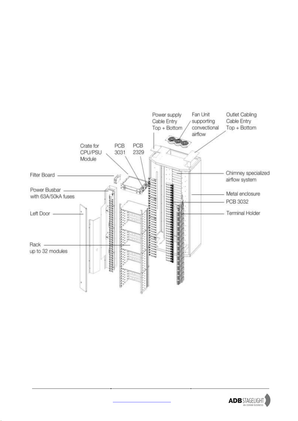
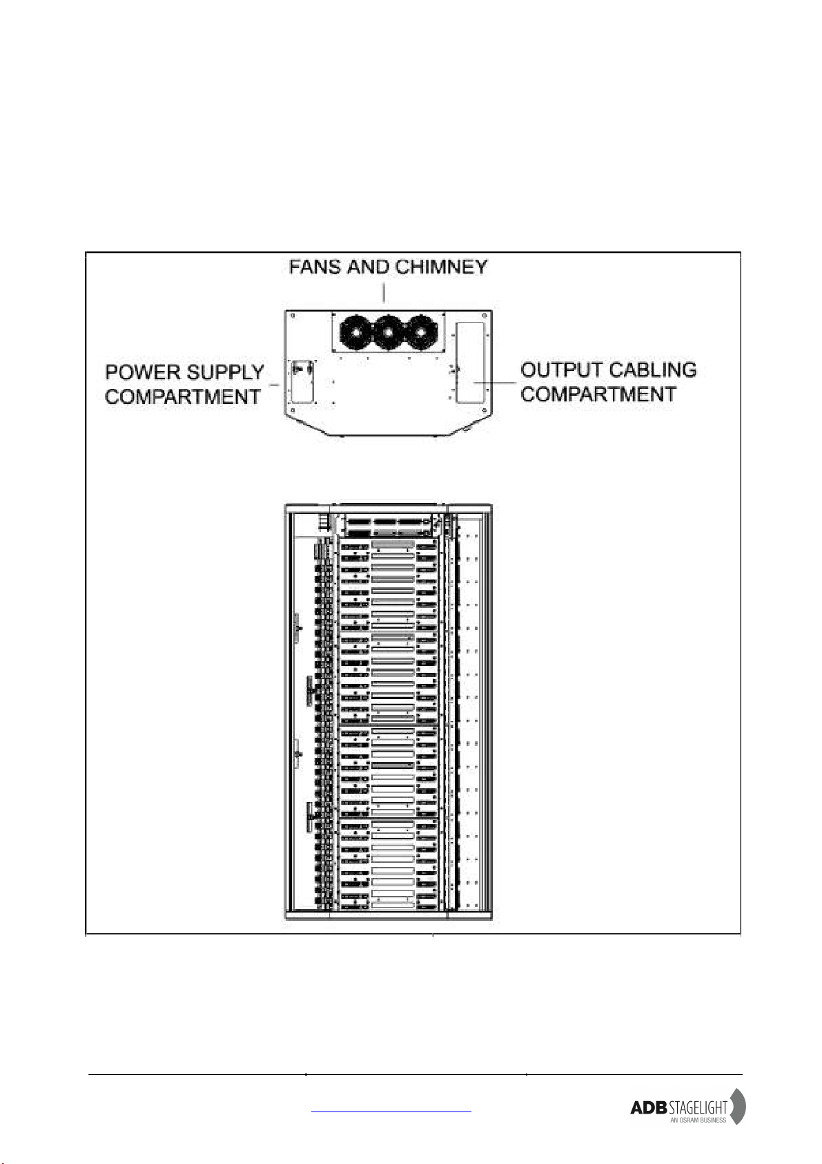
3 DESCRIPTION

EURODIM TWIN TECH
User Manual -page 12
Issue 2.1
www.adbstagelight.com
4 INSTALLATION
4.1 Dimmer room
4.1.1 Preparation
Determine the dimensions of the dimmer room so as to place all EURODIM Twin Tech
cabinets easily. Provide for an open space of approximately 90 cm in front of the cabinets
to facilitate maintenance. Before attempting to move the rack(s) into the final position,
check access routes to the dimmer room for space to manoeuvre through doorways and
around corridor corners. The cabinets can be placed against a wall, side by side or back to
back. The supply cables and the load cables can enter the wiring compartment either from
the top or bottom of the cabinet. See drawing for size and location of cable entries.
RISK OF FIRE
Install only on concrete or other non-combustible floor
Dimmer Room Requirements
•A clean (not dusty) temperature-controlled environment.
•Restricted public access to prevent any unauthorized tampering with the
dimmer settings.
•Soundproofing or performance area separation to muffle ventilation fan
noise. Acoustic measurements are available from ADB Lighting
Technologies.
•Provide for a free space, minimum 30 cm above the EURODIM Twin Tech
so as to facilitate the exhaust airflow. If an optional “Silencer” is used, then
more space may be necessary. The dimensions and weight of the cabinets are
included in the Chapter “Characteristics”. Plan for fire extinguishers in
compliance with local regulations. The lighting of the area should be
sufficient for maintenance and inspection. A level of 300 lux is considered
satisfactory. Plan for mains outlets in the room, independent of the supply
of the dimmers.
Plan for an Ethernet network to the control room and a cable for remote “CPU1 -CPU2”
selection (if applicable).
EURODIM Twin Tech cabinets are professional equipment and relevant safety rules are
applicable. EURODIM Twin Tech cabinets should be placed in areas that are accessible
only to persons responsible for maintenance, surveillance or repair of the equipment.
Please refer to local regulations and requirements.
The equipment shall be installed and serviced by skilled and trained personnel exclusively.
Such an area should be located as close as possible to the stage or studio, in order to
reduce the length of the electrical cables, and therefore, the cost of installation. At the time
of installation of the cabinets in the area, it should be completely unobstructed; that is, that
all engineering work, wall or floor covering work, painting, electric lighting work, drilling,

EURODIM TWIN TECH
User Manual -page 13
Issue 2.1
www.adbstagelight.com
welding, etc., must be completed.
Do not install the plug-in modules until all wiring installation is completed.
4.2 Ventilation of the dimmer room
The dimmer room should be dry at all times, free from dust and ventilated in such a
manner as to comply with the following:
-Relative humidity: 5% to 90% without condensation.
-Temperature between + 5 °C and + 35 °C (ideal: + 20 °C).
In order to size the air-conditioning equipment required for the dimmer room, refer to the
following dissipations:
-Cabinet electronics: 150 W global value for CPU(s), PSU and fans
-Thyristor modules:
o4 x 3 kW modules : 56 W per dimmer (worst case)
o3 x 5 kW modules : 76 W per dimmer (worst case)
o1 x 10 kW modules : 170 W per dimmer (worst case)
-Sinewave modules:
o4 x 2.5 kW modules : 60 W per dimmer (worst case)
-No-load losses of sine wave dimmers:
oSine wave dimmers have a no-load loss of approximately 4 W per dimmer.
In practice, you may consider a utility factor of 0.7: that is, on the average, 70% of the
dimmers are at full load, while 30% are off.
4.2.1 Example No. 1
A dimmer room with a EURODIM Twin Tech cabinet equipped with 128 thyristorsdimmers
of 3 kW and a second cabinet with 96 thyristorsdimmers of 5 kW. The cabinets are fitted
with a back-up power supply for the processor unit. Utility factor = 0.7
1) Cabinet N°1:
Electronics: 1 x 150 W
Dimmers 128 x 56 W x 0.7= 5017 W
2) Cabinet N°2:
Electronics: 1 x 150 W
Dimmers 96 x 76 W x 0.7= 5107 W
ROOM TOTAL: 10124 W
In this example, it will be necessary to evacuate approximately 10124 W of losses.
EURODIM TWIN TECH
User Manual -page 14
Issue 2.1
www.adbstagelight.com
4.3 Installation of the cabinets
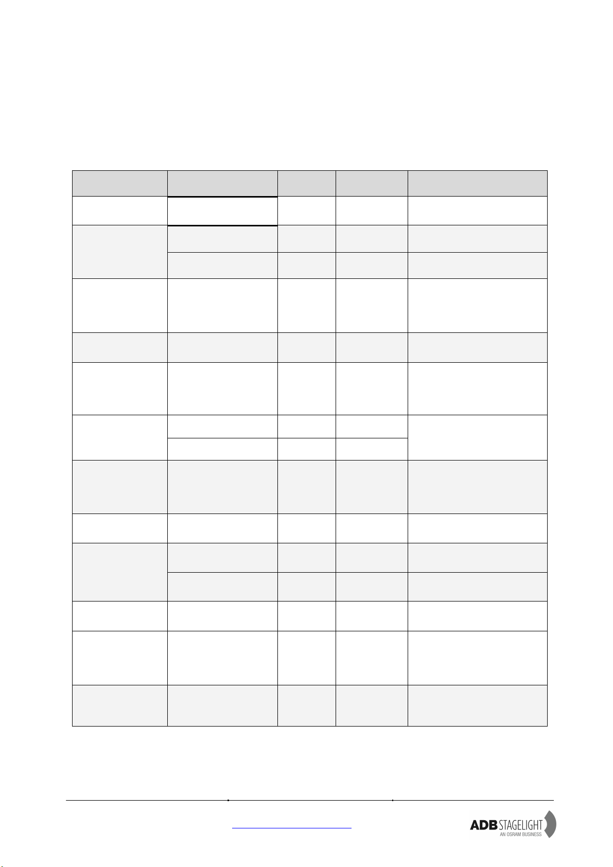
4.3.1 Tools for commissioning
Operation
Connection
Designation
Qty
Torque
Tools
Remove Doors
Pan Head Screw
M4x12 PZ
1
1,5 Nm
Screw Driver PZ2
Pan Head Screw
M4x12 PZ
5
2 Nm
Screw Driver PZ2
Remove Card
Cage Dimmers
Slotted Flat Head
Screw M4 x 12 PZ
16
1,5 Nm
Screw Driver PZ 2
Open Cables
aperture
In & Out
Pan Head Screw
M4x12 PZ
8
2 Nm
Screw Driver PZ 2
PE Connection
Power In
Nut M10
1
8 to 10 Nm
Metric Wrenches 17
Sequential
Diagnostics
(Optional)
Nut M 5 / Flat
Washers M 5 /
Helical Spring Lock
Washers M 5
2 of each
1,5 Nm
Metric Wrench 8
Nut M12
4
8 to 10 Nm
Input
Connection
(Bus Bar)
Bolt M12
4
8 to10 Nm
2 x Metric Wrenches 19
Output
Connection
(Output)
Terminal
Connection
Free Drive Screw
256
1,2 Nm
Flat Screw Driver 1 x 6, 5
(do not use power tools!)
PE connection
(Output)
Screws M4 x 8
128
1,2 Nm
Screw driver PZ 1
RJ 45
1
DMX
Connection
Phoenix MSTBVA
2,5 –6
6
0,5 Nm
Flat Screw Driver 0,5 x 3, 5
Ethernet
Connection
RJ 45
1
TTD Human
Interface
Nut M 4 / Flat
Washers M 4 /
Helical Spring Lock
Washers M 4
X4 (of
each)
1,5 Nm
Metric Wrench 7
Junction Plate
(Accessory)
Hex Cap Screw
M 16 x 25
4
3 Nm
Metric Wrenches 24
ADB recommend using Insulated Screwdriver.

EURODIM TWIN TECH
User Manual -page 15
Issue 2.1
www.adbstagelight.com
4.3.2 Packaging
The cabinets are shipped on a wooden pallet.
Standard transport position is vertical; first open the top panel after removing the screws
of the side panels.
The control processors, TTD Human Interface and dimmer modules are packed
separately.
4.3.3 Lifting Eyes (Optional Accessory)
If the cabinet must be elevated with a crane, use 4 lifting eyes TTD/CAB/LIFT kit
including 4 Lifting Eyes.
4.3.4 Junction Plate (optional part)
With the optional junction plate two cabinets can be connected to guarantee permanent
fixation.
EURODIM TWIN TECH
User Manual -page 16
Issue 2.1
www.adbstagelight.com
The weight and dimensions of the cabinets are included in Chapter “Characteristics”. Prior
to positioning each cabinet, ensure that the floor is flat and horizontal to ensure a good
weight distribution.
It is the responsibility of the system integrator or installer to check if the cabinet weight
load can be supported by the building structure!
After you have positioned the cabinets:
-Do not remove the plastic, so as to keep a protection during the cabling works.
-Cut the plastic to have an access to the cabling areas.
-Remove the doors of the contractor's areas by simply opening the door hinges.
CAUTION! The doors are grounded / earthed.
Gently remove this grounding connection
WHICH MUST BE RESTORED
when the door is eventually put back in place.
During the cabling works, leave the doors in a clean
area and covered with a protection.
EURODIM TWIN TECH
User Manual -page 17
Issue 2.1
www.adbstagelight.com
5 CONTRACTOR'S COMPARTMENT –SUPPLY
Front access only is required. Cable entry is possible through bottom and top of the
cabinet. Cover panels for the unused cable entry/ exit apertures are supplied.

EURODIM TWIN TECH
User Manual -page 18
Issue 2.1
www.adbstagelight.com
In order to gain maximum space
to access the cabinet for
installation and maintenance
purposes, remove the two doors,
loosen the 16 crosshead screws
in the back and 3 left + right at
the bottom and dismount the
entire card cage in one piece.
Mounting the cabinet, first insert
the card cage, enter two
dimmer modules to align the
rack and fasten the 16 screws.
Put the doors in place and
reconnect the doors earth
connection.
Table of contents
Other ADB Stagelight Dj Equipment manuals


Popular Dj Equipment manuals by other brands


Show Tec
Show Tec LED Par 64 36x3W Product guide

Show Tec
Show Tec Mirrorball Motor until 50 cm V2 manual

STUDIODUE
STUDIODUE Dual 80 user manual

Sound Sation
Sound Sation CLUBWASHER 3610 RGBW user manual

Vari Lite
Vari Lite VL6000 Beam Luminaire quick start guide

MegaLite
MegaLite Outshine Strip Q80 user manual