ADB Stagelight KLEMANTIS AS1000 User manual

INSTRUCTION MANUAL
KLEMANTIS
KLEMANTIS AS1000 (AL2001)
KLEMANTIS AS500 (AL2002)
www.adbstagelight.com
Congratulations on choosing an ADB product! We thank you for your custom.
Please note that this xture - like all the others in the wide ADB range - has been designed and made with total
quality assurance to ensure excellent performance and best meet your expectations and requirements.
EN

KLEMANTIS AS1000 - AS500
2
INDEX
1. AFETY INFORMATION
2. INTRODUCTION
2.1 Presentation
2.2 Main features and control options
2.3 Product overview
3. UNPACKING
3.1 Package contents
3.2 Accessories
4. IN TALLATION AND TART-UP
4.1 Installing the fixture
4.1.1 Introduction
4.1.2 Installation configurations
4.1.3 ow to calculate positioning distance from cyclorama
4.1.4 Focus and tilt angle
4.1.5 Tips&tricks
4.2 Connecting to main Supply
4.3 Connecting the control signal line: DMX / Art-Net
4.4 Control Panel
5. MAINTENANCE
5.1 Fuses replacing
5.2 Periodic cleaning
6. TECH DATA
7. APPENDIX
7.1 The Klemantis installation procedure

KLEMANTIS AS1000 - AS500
3
EN
IT
DE
E
FR
RU
ow to get a multilingual version of your SAFETY INSTRUCTIONS.
You may always download multilingual safety instruction for this ADB
product from:
https://www.adbstagelight.com/downloads
Ref: FIS01B - KLEMANTIS AS Safety Information
Come ottenere le INFORMAZIONI DI SICUREZZA nella versione
multilingue.
Puoi sempre scaricare la versione multilingue delle Informazioni
di Sicurezza per questo prodotto ADB al seguente link:
https://www.adbstagelight.com/downloads
Ref: FIS01B - KLEMANTIS AS Safety Information
So erhalten Sie Ihr INFORMATIONEN ZUR SIC ER EIT in der
mehrsprachigen Version.
Sie können die mehrsprachige Version des andbuchs mit
Sicherheitshinweisen für dieses ADB Produkt unter folgendem Link
herunterladen:
https://www.adbstagelight.com/downloads
Ref: FIS01B - KLEMANTIS AS Safety Information
Cómo obtener tu INFORMACIONES DE SEGURIDAD en la versión
multilingüe.
Siempre puedes descargar la versión multilingüe del Manual de
Instrucciones de Seguridad para este producto ADB en el siguiente
enlace.
https://www.adbstagelight.com/downloads
Ref: FIS01B - KLEMANTIS AS Safety Information
Comment obtenir votre CONSIGNES DE SÉCURITÉ dans la version
multilingue.
Vous pouvez toujours télécharger la version multilingue du Manuel
d’Instructions de Sécurité pour ce produit ADB au lien suivant :
https://www.adbstagelight.com/downloads
Ref: FIS01B - KLEMANTIS AS Safety Information
Где достать ИНСТРУКЦИЮ ПО ТЕХНИКЕ БЕЗОПАСНОСТИ на
нескольких языках.
Вы всегда ожете скачать ногоязычную инструкцию по технике
безопасности для данного изделия ADB пo ссылке:
www.adbstagelight.com/downloads
Ref: FIS01B - KLEMANTIS AS Safety Information
1. AFETY INFORMATION

KLEMANTIS AS1000 - AS500
4
The new ADB KLEMANTIS is an asymmetric cyclight based on a six-colour LED module, which uses cutting-edge CR LED technology to deliver a wide
selection of colours from bold hues to pastel shades.
Thanks to an innovative algorithm, the unit is capable of achieving a stable CRI of up to 99, as well as an impressive tunable white light ranging from 2500K
to 8000K.
Its light output is enhanced with an innovative optical unit, which enables the Klemantis to generate a uniform light with excellent diffusion and perfectly
blended colours.
The KLEMANTIS is available in two models, both designed to work in a linear array. The KLEMANTIS AS1000 is one metre long and fitted with 16 multi-
source LED modules. The KLEMANTIS AS500 is half a metre long and features 8 LEDs. They can be used horizontally, vertically, laid on the floor, or hung
from above on a bar. The AS500 is particularly suitable for lighting cyclorama corners.
Unlike any other light on the market, the KLEMANTIS can be installed very close to the cyclorama (as little as 60 cm away) without the light distribution
becoming uneven.
The Klemantis is a creative tool designed to meet today’s lighting design needs. Its unique features and design reinvent the cyclorama concept, making it
the perfect choice for any professional use.
An optional lens kit allows you to turn your asymmetrical optical unit into a symmetrical, fixed beam angle unit.
2. INTRODUCTION
2.1 Presentation
The Klemantis has several control modes which make managing the six-colour LED module easy. The user can choose the option that best suits their
programming preferences ranging from a simple three-channel RGB/CMY/ SL colour control mode, which gets the most from all six LED colours through
a sophisticated algorithm, to direct control over each colour source through six 16 bit dedicated DMX channels.
The way the Klemantis behaves can be tailored to any specific application by setting its dimming curve, adjusting its frequency rate and correcting its tint.
The unit ensures high colour stability and accuracy, fixture to fixture colour repeatability, and colour consistency over time.
Some of the main features and options include:
• Beam type: asymmetric flood
• Tunable white ranging from 2500K to 8000K, with perfect CCT
• Tungsten mode, to emulate the behaviour of a tungsten lamp during dimming from 0 to 100% and vice versa, including colour temperature adjustment
• Tint correction: +/- green/magenta adjustments
• 16-bit ultra-smooth dimming, with four different dimming curves available
• Smooth colour transition through different time, cross-fade and path options, and a gamma correction system
• Colour control: hue saturation luminosity ( SL), CMY, RGB (14 DMX ch. footprint) and RAW (27 DMX ch. footprint) modes fully exploit the potential of
the six-colour system
• Wide selection of digital filters (colour macros) which reproduce the spectrum of gel filters with tungsten bulbs
• igh colour stability and accuracy, even in tungsten mode, thanks to a high resolution driver
• Colour consistency over time and temperature changes, thanks to combined fixture calibration and an LED ageing compensation algorithm
• Fixture to fixture colour repeatability, thanks to tight wavelength binning selection and 100% fixture calibration
• Flicker-free, thanks to PWM frequency adjustment from 1 K z to 50 K z (10 z steps)
2.2 Main features and control options

KLEMANTIS AS1000 - AS500
5
2.3 Product overview
ADJUSTABLE FEET
TILT RELEASE LEVER
HANDLES
SAFETY ROPE ATTACHMENT POINTS
CAUTION. Possibly hazardous optical radia-
tion emitted from this product. Do not stare
at operating lamp. May be harmful to the eye.
Risk Group 2
According toIEC/EN62471
WARNING
MINIMUM DISTANCE OF INFLAMMABLE
MATERIALS FROM THE SURFACE 0.20 m
MAXIMUM TEMPERATURE OF
THE EXTERNAL SURFACE 90 C°°°
t
t
taata 4
4
ta4
00
ta40 °°
ta40 °CC
ta40 °C
0
00..0.220.2 mm0.2 m
WARNING RISK OF
DAMAGE
CONTIENE COLLIMATORI DI LUCE. EVITARE
LUCE INTENSA DA QUALSIASI ANGOLAZIONE
INTERNAL LIGHT COLLIMATION SYSTEM.
AVOID INTENSE LIGHT FROM ANY ANGLE
CONTIENT SYSTÈME DE COLLIMATION DE LUMIÈRE.
EVITER LUMIÈRE INTENSE DE N'IMPORTE QUEL ANGLE
DISCONNECT POWER
BEFORE CHANGING FUSES
USE REPLACEMENT FUSES
RATED T 4A 250V
COUPER LE COURANT AVANT
DE CHANGER LES FUSIBLES
EMPLOYER DES FUSIBLES DE
RECHANGE T 4A 250V
1
Fig. 1
Klemantis AS1000 components
POWER IN
DMX IN CONTROL PANEL USB PORT POWER OUT
DMX OUT
ETHERNET PORT
2
Fig. 2
Rear panel

KLEMANTIS AS1000 - AS500
6
3. UNPACKING
Package contents - Fig. 3
• 1x Safety Information Leaflet FIS01B
• 1x Omega Bracket 319102-801
• 1x powerCON TRUE 1 to Bare Ends Mains Cable CAB02B-801
3
HOWTO GET YOUR
USERMANUAL
Youmay always download the most up-to-date versionofthe user manual from:
www.adbstagelight.com/downloads
Youcan ask foran hardcopytothe ADBdistributorofyourarea
(www.adbstagelight.com/contacts/sales-network/).
The instructions inthe manual are essential forcorrect installation,maintenance
anduse ofthe appliance.
Inthe download area youcan also findthe followingdocuments:
t
Product Datasheets
t
Product Brochures
t
Set UpGuides
t
Quick StartGuides
t
Software Relese Notes
t
Software Files
Please read carefullythe attached safetyinstructions.
CONSIGNES
DESÉCURITÉ
Lireattentivement
INFORMATIONEN
ZURSICHERHEIT
Sorgfältiglesen
INFORMAZIONI
DI SICUREZZA
Leggereattentamente
INFORMACIONES
DESEGURIDAD
Leacuidadosamente
IИНФОРМАЦИЯ ПОТЕХНИКЕ БЕЗОПАСНОСТИвнимательно прочитайтеSAFETY
INFORMATION
3.1 Package contents

KLEMANTIS AS1000 - AS500
7
A D
B
E
C
1
3
24
1
3
2
1
4
3.2 Optional Accessories
AZ2001000200 Lenses 28°
AZ2001000210 Lenses 40°
Fig. 4
A - AZ2001000200 Kit Klemantis Symmetric Lenses 28° (2 sets of 0.5 meter)
AZ2001000210 Kit Klemantis Symmetric Lenses 40° (2 sets of 0.5 meter)
(provided in a box where both symmetrical and asymmetrical lenses can be stored)
B - ook clamp - ADB-1092.10.600
C - Safety bond - 105041/001
D - Junction pin - AA20000001020
E - Base accessory to mount 2 Klemantis - AR2001000000

KLEMANTIS AS1000 - AS500
8
4. IN TALLATION AND TART-UP
5
4.1 Installing the fixture
4.1.1 Introduction
The Klemantis’ unique asymmetric optical unit has been designed to respond to the increasing need to illuminate walls, scenery and cycloramas uniformly
with a smooth, even wash of seamlessly blended colours. The Klemantis ensures good colour consistency and uniform light distribution on very high
scenery, even when the lighting fixture and the projection surface are very close together.
One of the key aspects of the Klemantis is its special precise light intensity distribution. It should therefore be installed carefully in order to exploit its
potential and optimize its performance in cyclorama illumination.
4.1.2 Installation configurations
The Klemantis has been designed to work in a linear set-up, so the fixtures must be aligned in a continuous row. The maximum clearance allowed between
one fixture and the next is 20 mm.
Klemantis installation Fig. 5
Top and bottom configuration

Klemantis units may be installed in a bottom, top and bottom, or top only set-up, depending on the height of the surface to be lit and on the required
effect (total evenness of the light on the cyclorama or a linearly fading intensity effect).
When Klemantis units are installed in a single row (top or bottom), they create a uniform horizontal light distribution which fades vertically (see Fig. 1).
When they are installed on the floor and on the ceiling (top and bottom rows) at the same distance from the cyclorama, they create an outstandingly
uniform vertical light distribution (see Fig. 2). Top and bottom set-up is ideal in order to achieve the most even light distribution on the cyclorama.
Figure 1
single row setup
Figure 2
top and bottom row setup
0
1000
Y, mm
2000
3000
4000
-1000
-2000
-3000
-4000
0
X, mm
1000 2000 3000 4000 5000-1000-2000-3000-4000-5000
0
1000
Y, mm
2000
3000
4000
-1000
-2000
-3000
-4000
0
X, mm
1000 2000 3000 4000 5000-1000-2000-3000-4000-5000
6
Fig. 6
Klemantis' performance with different installation configurations
KLEMANTIS AS1000 - AS500
9

KLEMANTIS AS1000 - AS500
10
Installing the fixture - Fig. 7
The fixture can be installed on the floor, on a truss, on the ceiling or on a wall.
WARNING: safety cables must be installed in every case except when the fixture is on the ground. (Code 2X 105041/001 available on request.)
The safety cables must be fastened to the unit supporting structure and then hooked onto the fastening points found on the sides of the
fixture.
Safety cables must be
inserted in the two
anchor points and
attached to the truss
WARNING: light collimation system
This unit contains an internal light collimation system.
Avoid intense light from any angle.
7

KLEMANTIS AS1000 - AS500
11
4.1.3 How to calculate the installation distance from a cyclorama
In the case of the two-row set-up, the recommended distance for the most even light on a cyclorama can be easily calculated using the following formula:
d = distance from cyclorama
= height of cyclorama
d = H
8
D
Distance (D)
Cyclo Height (H)
Klemantis
H
8

KLEMANTIS AS1000 - AS500
12
4.1.4 Focus and tilt angle
The Klemantis performs best if tilted 45°
When one Klemantis is installed properly in place (at the correct distance, perfectly parallel to the wall and tilted 45°), the light distribution on the cyclorama
looks like a rectangular distribution with soft edges on the sides and soft vertical fading.
If the lighted area has a trapezoidal shape, correct the tilt angle until the projection sides become straight and parallel (fig. 9a)
Summary of check points for correct installation
• Make sure the Klemantis is aligned parallel to the wall
• Check the unit tilt angle (45° is the recommended angle for best performance)
• Check the distance between the fixture and the projection surface (see point 4.1.3 of the User Manual for detailed instructions)
4.1.5 Tips & Tricks
The biggest issues which occur in case of improper installation are:
- Gaps or peaks, which appear in the vertical light half way up the cyclorama.
• Tilting effect: if tilted upwards, the generated target light-rectangle becomes a trapezium with major base on the bottom. If tilted downwards, the
generated target light-rectangle becomes a trapezium with major base on the bottom adjust the Klemantis's tilting
- Narrow vertical gaps in light (10 - 30 cm), which appear on the cyclorama from either floor or ceiling Klemantis units.
• Clearance effect: there might be too large a clearance between two adjacent Klemantis units reduce this clearance by installing the units closer
together.
- Uneven horizontal light distribution (>1 m), which appears on the cyclorama from either floor or top Klemantis units.
• The Klemantis units are not parallel to the cyclorama re-arrange the units along a straight line which is parallel to the cyclorama.
- Vertical colour transition does not change horizontally in two-row installation, when floor and ceiling rows are set to two different colours.
• Tilting effect: if the Klemantis units on the same row are not tilted properly and equally, the light intensity varies on the cyclorama adjust Klemantis
tilting.
Should you require further instructions about installation, see Appendix: Klemantis Installation Steps.
d = H
8
9b9a 9c
9
Focus Fig. 9
9a: correct - 9b, 9c: wrong

KLEMANTIS AS1000 - AS500
13
4.2 Connecting to main power supply
1
2
MAINS IN
10
Attach the power cable to the Power In connector - Fig. 10
1
2
MAINS IN
11
Link additional fixtures via the Power Thru connector - Fig. 11
Up to five Klemantis AS1000s (or eight Klemantis AS500s) may be linked via Power Thru connectors on the same power line (16 Amp).
NOTE: plug the cable into AC power 100/240V 50/60 z on a non-dimmable circuit. Do not connect to a dimmer power line.

KLEMANTIS AS1000 - AS500
14
4.3 Connecting the control signal line: DMX / Art-Net
DMX IN
DMX OUT
12
SIGNAL
SCREEN
DMX 512
5 PIN
1
2
3
4
5
SIGNAL
DMX 512
IN OUT
13
Connecting the control signal line: DMX / Art-Net - Fig. 12-13
Use a cable conforming to specifications EIA RS-485: 2-pole twisted, shielded, 120Ωcharacteristic impedance, 22-24 AWG, low capacity. Do not use
microphone cable or other cable with characteristics differing from those specified.
Use XLR type 5-pin male/female connectors for end connections. A terminating plug with a resistance of 120 (minimum 1/4 W) between terminals 2 and
3 must be inserted on the last unit.
IMPORTANT: Avoid contact between wires and with the metal casing of the connector.
The casing must be connected to the shield braid and pin 1.

KLEMANTIS AS1000 - AS500
15
4.4 Control panel
14
15
witching the fixture on - Fig. 14
The fixture comes on immediately when the power cord is plugged in.
Menu settings status
If no button is pressed, the display automatically returns to idle status after a time-out interval of about 60 seconds. Any modified value that has not yet
been confirmed with the
A
key will be cancelled.
B tton f nctions – Men SET prod ct overview front panel
• If pressed in idle stat s: Cyclically switches between idle status and menu settings.
• If pressed while setting a men : Moves to an upper level without changing anything (exits the function)
Decreases the value displayed (with auto-repetition), or passes to the next item on the menu
For quick access to the minimum parameter value, press the UP key while holding down the DOWN key.
Increases the value displayed (with auto-repetition), or passes to the previous item on the menu
For quick access to the maximum parameter value, press the DOWN key while holding down the UP key.
Confirms the displayed value, activates the displayed function or opens the next menu.
SELECT
DOWN
UP
ENTER
28
28
Display inversion - Fig. 14
To activate this function press the UP
B
and DOWN
C
keys at the same time while the display is in standby.
The condition is memorized and saved for subsequent switching too. To return to the initial state, repeat the operation again.

KLEMANTIS AS1000 - AS500
16
5. MAINTENANCE
5.1 Replacing fuses
1
2
3
Two 6.3 x 32 mm
4AT fuses
(p/n FUS00B)
16
Replacing fuses - Fig. 16
Each fixture has two fuses on the main power cord connection.

KLEMANTIS AS1000 - AS500
17
5.2 Routine cleaning
17
Routine cleaning - Fig. 17
To ensure optimal operation and performance for a long time it is essential to clean the parts subject to dust and grease deposits periodically. The
frequency with which the following operations need to be carried out depends on various factors such as wear and the working environment (air humidity,
dust, salinity, etc.).
We recommend that the fixture undergoes annual servicing by a qualified technician for special maintenance involving at least the following operations:
• General cleaning of internal parts.
• General visual check of internal parts, cabling, mechanical parts, etc.
• Electrical, photometric and functional checks; any necessary repairs.
IMPORTANT: Do not use compressed air at more than four atmospheres to clean the inside of the fixture (LED board area).
Clean the lenses using water and neutral soap only. Then dry thoroughly with a soft, non-abrasive cloth. (CAUTION: the use of alcohol or other detergents
could damage the lenses).
Parts requiring frequent cleaning.

KLEMANTIS AS1000 - AS500
18
6. TECH DATA
400
(15.75")
1000
(39.37")
192
(7.56")
271
(10.67")
400
(15.75") 192
(7.56")
271
(10.67")
500
(19.68")
KLEMANTI A 1000 - A 500
ELECTRICAL PEC
• Power supply: electronic auto-ranging
• Input voltage range: 110-240Vac 50/60 z
• Max power consumption: 280 VA at 230V/50 z (AS1000)
• Max power consumption: 170 VA at 230V/50 z (AS500)
POWER CONNECTION
• Power input: Neutrik PowerCON TRUE 1
• Power thru: Neutrik PowerCON TRUE 1 (daisy chain up to 5 x Klemantis
AS1000)
DATA CONNECTION
• Control protocols: DMX512 / RDM / Art-Net 4 / RDM over Art-Net 4
• Wireless control: available
• Data IN connector: 5 pins XLR + RJ45
• Data OUT connector: 5 pins XLR
MECHANICAL PEC
• Painting: black with epoxidic powder
• Body: extruded aluminium and steel sheet
• Cooling system: automatic fan with variable speed/ LED cooling by
natural convection
• Max noise level: 24.5 dB(A) @ 1m
• IP protection rate: IP20
WEIGHT
Klemantis AS500: 11 kg
Klemantis AS1000: 16 kg
OPERATIONAL PEC
• Working position: 45° std, rot. +/-45°
• Min. distance to illuminated surface: 0.2m
• Ambient temp. (min-max): -20°C / +40° C
• Maximum surface temperature: 90°
OPTICAL PEC
• Source: 8/16 CR Exclusive LED module featuring six colors: Red +
Green + Blue + Cyan + Amber + Lime
• Lifetime L70: 57,000 h
• Color temperature: Tunable white ranging from 2500K to 8000K, with
perfect CCT
• CRI >97 throughout the entire CCT (up to 99)
• Optics: FFL Asymmetric, proprietary optical design
• orizontal spread: 49°
• Vertical spread: 108°
APPROVAL
• CE / ETL
PROVIDED WITH
• Neutrik PowerCON TRUE 1 power cable/bare ends (1.5m cable PVC
insulated 3X1.5mm)
• Omega bracket

KLEMANTIS AS1000 - AS500
19
7. APPENDIX
7.1 Klemantis installation steps
The following steps summarize the recommended procedure for installing a single row of units (for instance on the floor):
1. Calculate the proper installation distance (D) from the cyclorama.
2. Place the Klemantis stably and make sure all Klemantis units are parallel to the cyclorama, at the set distance (D). Reduce the gap between two
adjacent fixtures to a minimum (1 - 2 mm).
3. If the floor is not level, use the adjustable feet
(fig. 18)
4. Adjust the tilt of each unit (a digital bubble level smartphone app may be used):
a. Before tightening the clamps, set all the Klemantis units to 0° in the back-stage-to-front-stage direction
(fig. 19)
.
18
19

KLEMANTIS AS1000 - AS500
20
b. Loosen the tilting knobs so that the Klemantis units may be tilted (fig. 20).
c. Place your smartphone in the middle of the Klemantis housing as shown in the picture (fig. 21), so that the plastic bulges on the top surface between
the lenses define the slope of your smartphone.
d. Set the tilt angle to 43.5° to the vertical (wall) or 46.5° to the horizontal (floor) (fig. 21-22). The correct reference angles are shown in the layout for
completeness (fig. 23).
20
43.5°
21
43.65°
46.35°
45.00°
45.00°
23 24
46.5°
22
This manual suits for next models
3
Table of contents
Other ADB Stagelight Dj Equipment manuals
Popular Dj Equipment manuals by other brands

Snow Business
Snow Business SB200 Booster owner's manual

MAX LIGHT
MAX LIGHT PartyBar11 instruction manual
thomann
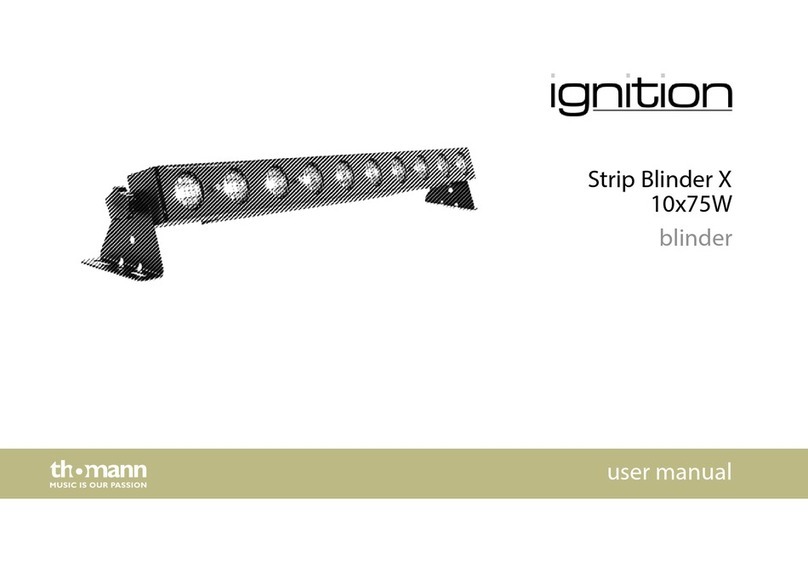
thomann igniton Strip Blinder X 10x75W user manual

BOTH LIGHTING
BOTH LIGHTING S6mini user manual
Chauvet DJ
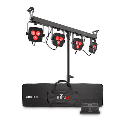
Chauvet DJ 4BAR Flex T USB user manual
Insta
Insta instalight 1065 R A single 920mm operating instructions
