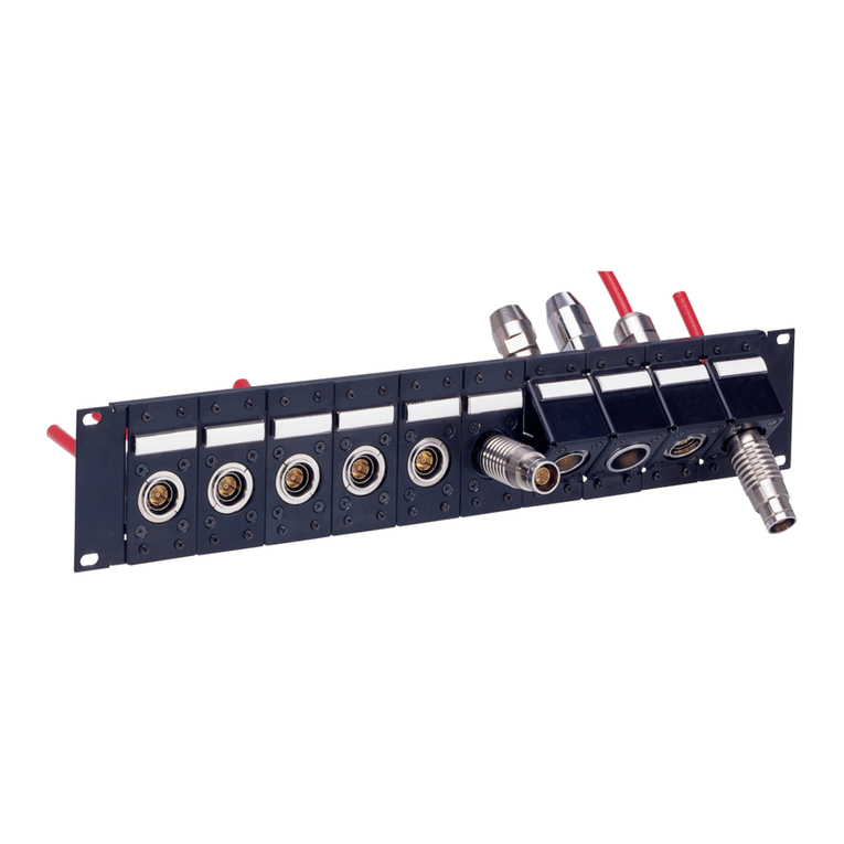
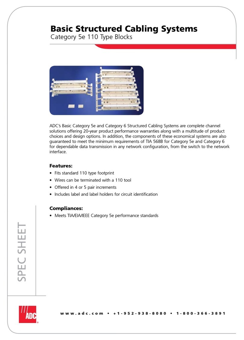
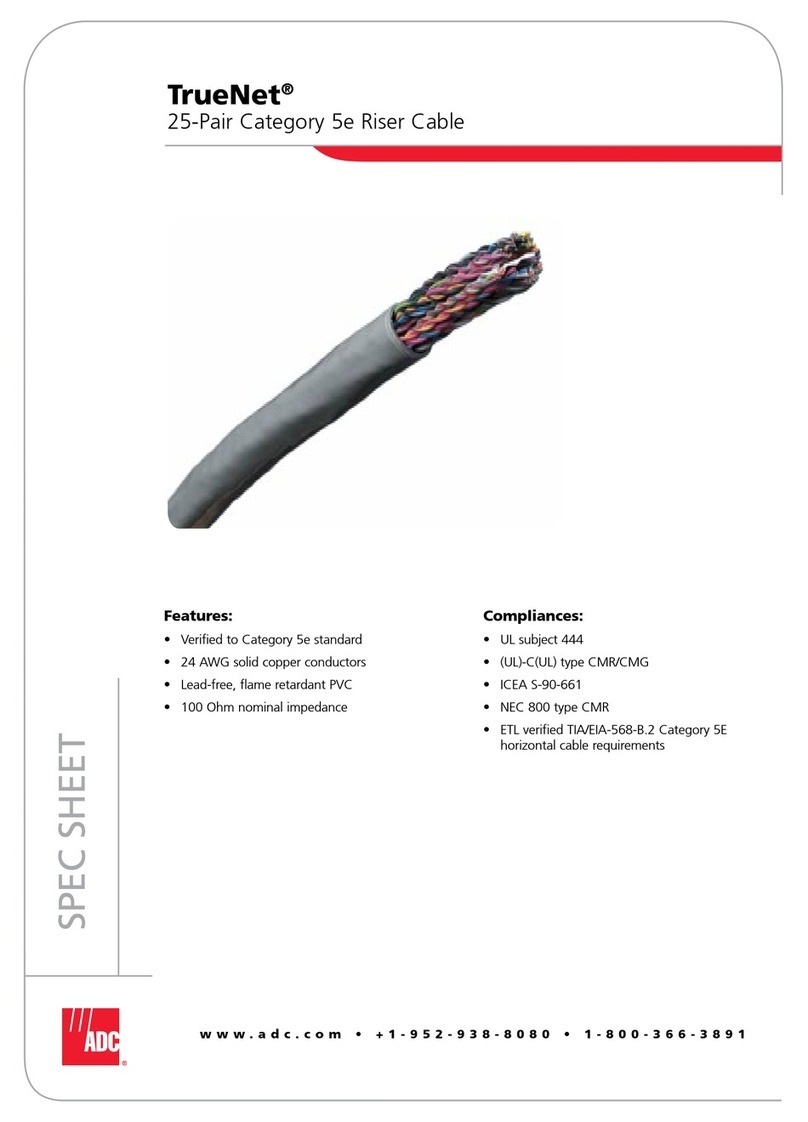
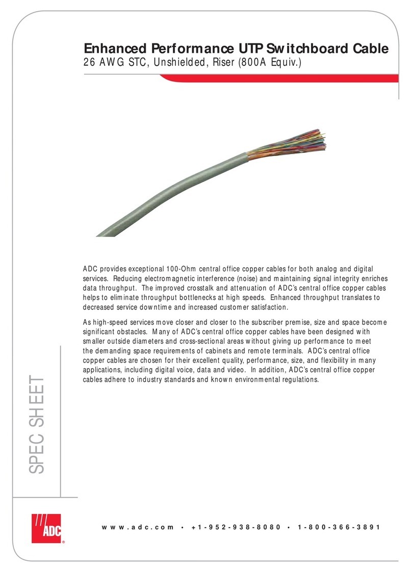
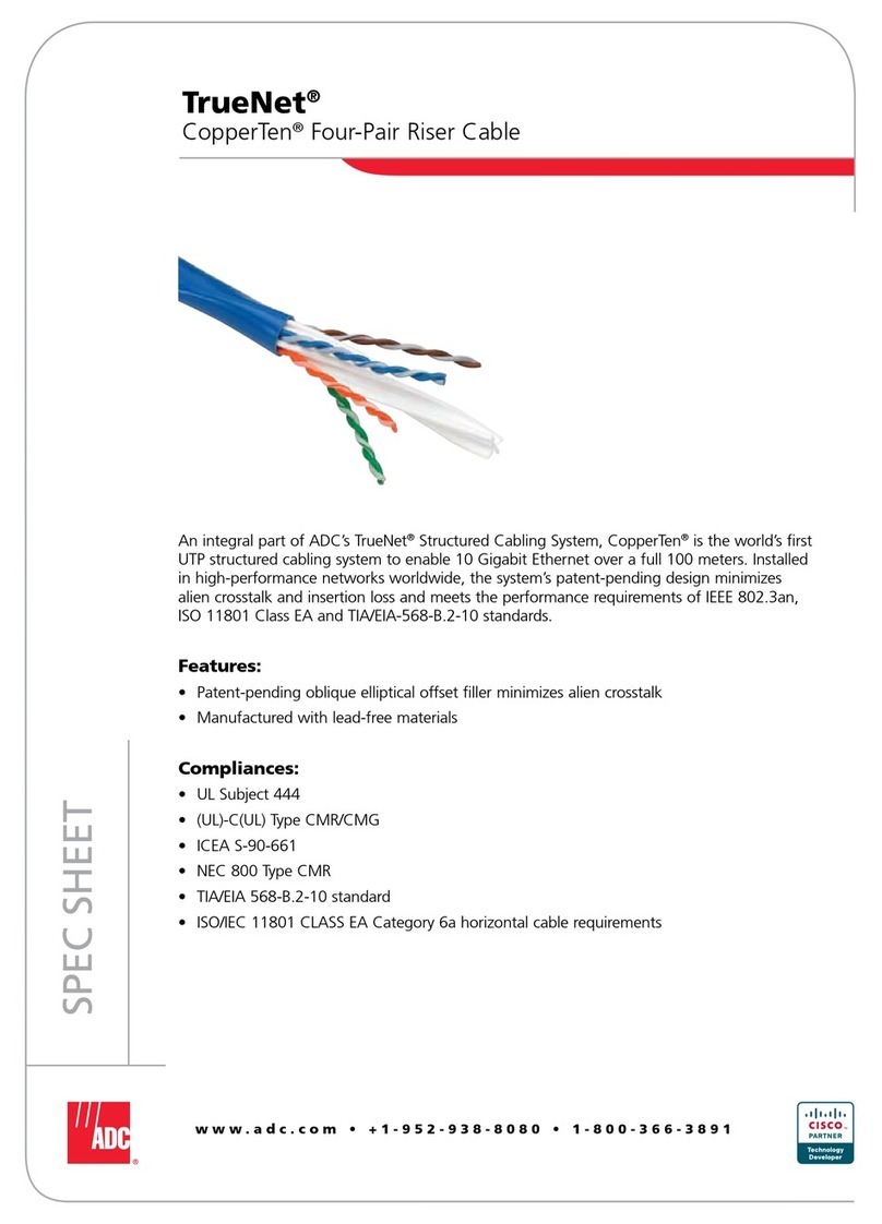
ADC DSX-1 User manual

ADCP-80-325 •Issue 4 •January 2001
4-26007-0050 Rev B Page 1
2001, ADC Telecommunications, Inc.
DSX-1 and DSX-1C
Cross-Aisle Panel
User Manual
Content Page
INTRODUCTION .......................................................................... 1
Revision History ..................................................................... 1
Trademark Information ................................................................ 1
Admonishments ..................................................................... 2
1 GENERAL.......................................................................... 2
2 DESCRIPTION....................................................................... 2
3 APPLICATION ....................................................................... 3
3.1 Direct Cross-Aisle Wiring ......................................................... 3
3.2 Zoned Cross-Aisle Wiring ......................................................... 3
3.3 Ratio of Cross-Aisle Ties.......................................................... 6
4 INSTALLATION ...................................................................... 7
4.1 Panel Mounting................................................................ 7
4.2 Installation Drawing............................................................. 7
4.3 Cross-Aisle Panel Cabling......................................................... 8
4.3.1 Cross-Aisle Tie Cable Type ................................................. 8
4.3.2 Cross-Aisle Tie Cable Connections ............................................ 8
4.4 Cross-Connects ................................................................ 9
4.4.1 Cross-Connect Wire Type .................................................. 9
4.4.2 Cross-Connect Length..................................................... 9
4.4.3 Cross-Connect Wiring ..................................................... 10
5 CUSTOMER INFORMATION AND ASSISTANCE ................................................. 13
INTRODUCTION
This manual describes the ADC DSX-1 Cross-Aisle Panels and their use in multiple lineup
DSX-1 Systems.
Revision History
ISSUE DATE REASON FOR CHANGE
Issue 1 04/1996
Issue 2 09/1996
Issue 3 08/1997
Issue 4 01/2001 Non-technical update.
Trademark Information
ADC is a registered trademark of ADC Telecommunications, Inc.

ADCP-80-325 •Issue 4 •January 2001
Page 2
2001, ADC Telecommunications, Inc.
Admonishments
Important safety admonishments are used throughout this manual to warn of possible hazards
to persons or equipment. An admonishment identifies a possible hazard and then explains
what may happen if the hazard is not avoided. The admonishments — in the form of Dangers,
Warnings, and Cautions — must be followed at all times. These warnings are flagged by use
of the triangular alert icon (seen below), and are listed in descending order of severity of
injury or damage and likelihood of occurrence.
Danger:Danger is used to indicate the presence of a hazard that will cause severe personal
injury, death, or substantial property damage if the hazard is not avoided.
Warning:Warning is used to indicate the presence of a hazard that can cause severe
personal injury, death, or substantial property damage if the hazard is not avoided.
Caution:Caution is used to indicate the presence of a hazard that will or can cause minor
personal injury or property damage if the hazard is not avoided.
1 GENERAL
This manual describes ADC’s DSX-1 Cross-Aisle Panels and their application in multi-lineup
DSX-1 Systems. This manual also provides complete instructions for installing the Cross-
Aisle Panel in a bay. Procedures for mounting, cabling, and wiring the panels in the bay are
included. The manual includes recommended inter-lineup wiring configurations and
installation instructions. It is recommended that the entire manual be read and understood
before beginning the actual installation.
2 DESCRIPTION
Cross-Aisle Panels are termination fields for tie cables between bay lineups. Use of these
panels eliminates the need for individual overhead cross-connect wires from one lineup to
another. Bay lineups are interconnected by means of tie cables terminated to Cross-Aisle
Panels on each lineup. DSX circuits in separate lineups are then interconnected by installing
cross-connect wires from each DSX circuit to the Cross-Aisle Panel in the same lineup.
Atypical Cross-Aisle Panel is showninFigure 1.Cross-Aisle Panels are available invarious
dimensions with either 50, 100, or 200 five-wire terminations. Cross-Aisle Panels are also
available in 50 or 100 six-wire terminations. Specifications for the Cross-Aisle Panels can be
found in ADC catalog number 256, DSX-1 Modules and Panels.

ADCP-80-325 •Issue 4 •January 2001
Page 3
© 2001, ADC Telecommunications, Inc.
TL
T
R
T1
R1
OUT
IN
TL
T
R
T1
R1
OUT
IN
1 5 10 15 20 25 30 35 40 45 50 55 60 65 70 75 80 85 90 95 100
FRONT VIEW
REAR VIEW 8382-A
Figure 1. DSX-CAP BEST Cross-Aisle Panel
3 APPLICATION
Cross-Aisle Panels or space for these panels should be provided in every bay of a DSX
multiple-lineup. All wiring is point-to-point with no multiples. ADC recommends one of the
following Cross-Aisle Panel cable designs:
•Direct wiring between like numbered bays as shown in Figure 2.
•Zoned wiring as shown in Figure 3.
Note: The circuit count and numbering system is an example only and may be changed
depending on local practices. These examples show how a unique numbering system can
be used no matter how circuits are provided.
3.1 Direct Cross-Aisle Wiring
In Figure 2,all Cross-Aisle Panels are cabled between the same numbered bays ineach lineup.
In this direct wiring design cross-connect wires are run from the Cross-Aisle Panel in the bay
where they originate to the associated Cross-Aisle Panel in the same numbered bay of another
lineup. This means that no horizontal wireway is required in the originating bay. The cross-
connect is then extended to the terminating location, in most cases using a horizontal wireway
in the second lineup.
3.2 Zoned Cross-Aisle Wiring
In Figure 3,Cross-Aisle Panels are cabled between the same bays as inFigure 2,they are also
cabled between like positioned bays ineach zone. Figure 3showsCross-Aisle Panel cable
routing for a two-zone cross-aisle tie wiring arrangement. This figure shows how the first bays in
each zone are interconnected (all bay 1s and bay 11s). The cabling between other bays is not
shown but is done in the same manner (all bay 2s and bay 12s, all bay 3s and bay 13s, etc.).

ADCP-80-325 •Issue 4 •January 2001
Page 4
2001, ADC Telecommunications, Inc.
LINEUP
1
01 02 03 04 05 06 07 08 09 10 11 12 13 14 15 16 17 18 19 20
2
DENOTES LINEUP 1 TO LINEUP 2 AND LINEUP 2 TO LINEUP 3.
DENOTES LINEUP 1 TO LINEUP 3.
1
2
3
DOUBLE LINEUP
TRIPLE LINEUP
8383-A
NOTE:
Figure 2. DSX-1/1C Cross-Aisle Panel Direct Wiring
01 02 03 04 05 06 07 08 09 10
01 02 03 04 05 06 07 08 09 10
01
1
LINEUP
3
202 03 04 05 06 07 08 09 10
11 12 13 14 15 16 17 18 19 20
11 12 13 14 15 16 17 18 19 20
11 12 13 14 15 16 17 18 19 20
1–501–50
1–50 1–50
51–100
51–100
51–100
101–150
1–50
51–100
101–150101–150
101–150 101–150
151–200
151–200
151–200 151–200
151–200
151–200
ZONE 2
ZONE 2
8384-A
Figure 3. DSX-1/1C Cross-Aisle Panel Two Zone Wiring
Table 1showspoint-to-point information for interconnecting three lineups with 20 bays each.
In this example 200 cross-aisle circuits are provided in each bay with 50 circuit complements
distributed as shown in Figure 3.
Zoned cross-aisle tie cabling systems may contain as many zones as desired. However, each
zone should have the same number of bays. This allows the cable complements to be equally
distributed between each set of bays. With the zoned cross-aisle design, jumpers use Cross-
Aisle Panels in the bay where they originate (no horizontal wireway necessary) to an
associated Cross-Aisle Panel located in the other lineup nearest the terminating location. The
cross-connect is then extended in that lineup to the terminating location using the horizontal
wireway unless termination is in the same bay.

ADCP-80-325 •Issue 4 •January 2001
Page 5
© 2001, ADC Telecommunications, Inc.
Table 1. Two Zone Cross-Aisle Panel Wiring
LINEUP/BAY CIRCUIT LINEUP/BAY CIRCUIT
FROM TO COUNT FROM TO COUNT
1/01 2/01 51-100 1/06 2/06 51-100
1/01 2/11 101-150 1/06 2/16 101-150
1/01 3/01 1-50 1/06 3/06 1-50
1/01 3/11 151-200 1/06 3/16 151-200
2/01 1/11 151-200 2/06 1/16 151-200
2/01 3/01 101-150 2/06 3/06 101-150
2/01 3/11 1-50 2/06 3/16 1-50
3/01 1/11 51-100 3/06 1/16 51-100
3/01 2/11 151-200 3/06 2/16 151-200
1/02 2/02 51-100 1/07 2/07 51-100
1/02 2/12 101-150 1/07 2/17 101-150
1/02 3/02 1-50 1/07 3/07 1-50
1/02 3/12 151-200 1/07 3/17 151-200
2/02 1/12 151-200 2/07 1/17 151-200
2/02 3/02 101-150 2/07 3/07 101-150
2/02 3/12 1-50 2/07 3/17 1-50
3/02 1/12 51-100 3/07 1/17 51-100
3/02 2/12 151-200 3/07 2/17 151-200
1/03 2/03 51-100 1/08 2/08 51-100
1/03 2/13 101-150 1/08 2/18 101-150
1/03 3/03 1-50 1/08 3/08 1-50
1/03 3/13 151-200 1/08 3/18 151-200
2/03 1/13 151-200 2/08 1/18 151-200
2/03 3/03 101-150 2/08 3/08 101-150
2/03 3/13 1-50 2/08 3/18 1-50
3/03 1/13 51-100 3/08 1/18 51-100
3/03 2/13 151-200 3/08 2/18 151-200
1/04 2/04 51-100 1/09 2/09 51-100
1/04 2/14 101-150 1/09 2/19 101-150
1/04 3/04 1-50 1/09 3/09 1-50
1/04 3/14 151-200 1/09 3/19 151-200
2/04 1/14 151-200 2/09 1/19 151-200
2/04 3/04 101-150 2/09 3/09 101-150
2/04 3/14 1-50 2/09 3/19 1-50
3/04 1/14 51-100 3/09 1/19 51-100
3/04 2/14 151-200 3/09 2/19 151-200
(continued)

ADCP-80-325 •Issue 4 •January 2001
Page 6
2001, ADC Telecommunications, Inc.
Table 1. Two Zone Cross-Aisle Panel Wiring, continued
LINEUP/BAY CIRCUIT LINEUP/BAY CIRCUIT
FROM TO COUNT FROM TO COUNT
1/05 2/05 51-100 1/10 2/10 51-100
1/05 2/15 101-150 1/10 2/20 101-150
1/05 3/05 1-50 1/10 3/10 1-50
1/05 3/15 151-200 1/10 3/20 151-200
2/05 1/15 151-200 2/10 1/20 151-200
2/05 3/05 101-150 2/10 3/10 101-150
2/05 3/15 1-50 2/10 3/20 1-50
3/05 1/15 51-100 3/10 1/20 51-100
3/05 2/15 151-200 3/10 2/20 151-200
1/11 2/11 1-50 1/16 2/16 1-50
1/11 3/11 101-150 1/16 3/16 101-150
2/11 3/11 51-100 2/16 3/16 51-100
1/12 2/12 1-50 1/17 2/17 1-50
1/12 3/12 101-150 1/17 3/17 101-150
2/12 3/12 51-100 2/17 3/17 51-100
1/13 2/13 1-50 1/18 2/18 1-50
1/13 3/13 101-150 1/18 3/18 101-150
2/13 3/13 51-100 2/18 3/18 51-100
1/14 2/14 1-50 1/19 2/19 1-50
1/14 3/14 101-150 1/19 3/19 101-150
2/14 3/14 51-100 2/19 3/19 51-100
1/15 2/15 1-50 1/20 2/20 1-50
1/15 3/15 101-150 1/20 3/20 101-150
2/15 3/15 51-100 2/20 3/20 51-100
The zoned cross-aisle cabling system results in shorter jumpers and thereby reduces horizontal
jumper pileup.
3.3 Ratio of Cross-Aisle Ties
The ratio of cross-aisle ties to the number of equipment terminations in a bay may vary
greatly, depending on the design of the lineups. Cable considerations include:
• Quantity of DSX terminations in each bay. Typical seven foot DSX bays may have from
450 to 1008 terminations.
• Spread of equipment terminations within each bay. If multiplexers and digital switch
terminations are located in the same bay, fewer cross-connect wires will leave that bay
than if the multiplexers and switch terminations are located in different bays.
• Short cross-connect concept. Preferential assignment or software is used always to select
the shortest possible cross-connect.
ADCP-80-325 •Issue 4 •January 2001
Page 7
© 2001, ADC Telecommunications, Inc.
If assignments are made completely at random in a three-lineup system, it is possible that
about two-thirds of the cross-connect wires will leave a lineup. If assignments are completely
contained in a lineup, no cross-connect wires will leave that lineup. Most offices will be
somewhere between these two extremes. It is recommended that a minimum ratio of 25%
cross-aisle tie circuits to DSX termination be provided. It may be prudent to leave room for
another cross-aisle panel to be installed at a later date as the lineups mature.
4 INSTALLATION
Installation of Cross-Aisle Panels involves mounting of the panels on the various bays and
interconnecting them between the lineups.
Warning:To prevent electrical shock, never install Cross-Aisle Panels in a wet location or
during a lightning storm. When installing or modifying telephone lines, disconnect lines at the
network interface before working with uninsulated lines or terminals.
4.1 Panel Mounting
Install all Cross-Aisle Panels in the assigned bay locations using 12 – 24 ×1/2 inch mounting
screws.
Note: The 12 – 24 ×1/2 inch mounting screws must be ordered separately.
4.2 Installation Drawing
Each panel is shipped with an installation drawing. This drawing defines the specific input and
output terminations on the Cross-Aisle Panel.
Figure 4shows atypical installation drawing. The Cross-Aisle Panel shown inFigure 4has
100 DSX circuits.
In a front cross-connect DSX system the front of the Cross-Aisle Panel is used to connect
cross-connect jumpers. The back is used to connect tie cables from a Cross-Aisle Panel in one
lineup to a Cross-Aisle Panel in another lineup.
In a rear cross-connect system, the back of the Cross-Aisle Panel is used to connect cross-
connect jumpers. The front is used to connect tie cables from a Cross-Aisle Panel in one
lineup to a Cross-Aisle Panel in another lineup.

ADCP-80-325 •Issue 4 •January 2001
Page 8
2001, ADC Telecommunications, Inc.
TL
T
R
T1
R1
OUT
IN
TL
T
R
T1
R1
OUT
IN
1 5 10 15 20 25 30 35 40 45 50 55 60 65 70 75 80 85 90 95 100
8385-A
REMOVABLE CABLE TRAY
(NOT MOUNTED BY ADC)
22.312 IN. 56.7 CM)
(REF) 23.00 IN. 58.4 CM)
(REF)
29.30 IN. ±.25 IN.
(74.4 CM ±.6 CM)
3.00 IN.
(7.64 CM)
(REF)
4.00 IN.
(10.16 CM)
MAX
1.60 IN.
(4.06 CM)
(REF)
19.80 IN.
(50.3 CM)
(REF)
G
W
BL
W
O
G
W
BL
W
O
G
W
BL
W
O
G
W
BL
W
O
W
W
W
W
W
G
W
BL
W
O
G
W
BL
W
O
W
W
W
W
W
G
W
BL
W
O
G
W
BL
W
O
W
W
W
W
W
G
W
BL
W
O
G
W
BL
W
O
TL
T
R
T1
R1
TL
T
R
T1
R1
OUT
IN
OUT
IN
1 5 95 100
COLOR SCHEME DETAIL
(EVERY 5TH CIRCUIT IS WHITE)
W
BL
O
G
WHITE
BLUE
ORANGE
GREEN
COLOR CHART
Figure 4. Typical Information Shown on Installation Drawing
4.3 Cross-Aisle Panel Cabling
4.3.1 Cross-Aisle Tie Cable Type
Recommended cable for cross-aisle cable ties is shielded twisted pair cable 26 AWG, similar
to AT&T 1249 cable. Separate cable should be used for each direction of the circuit. Ground
the cable shield at one end only.
4.3.2 Cross-Aisle Tie Cable Connections
Connect the tie cables tothe wire-wrap terminals onthe Cross-Aisle Panels. Figures 2and 3
show Cross-Aisle Panel wiring in typical multi-lineup systems. One recommended method of
wiring is to connect the OUT terminals in one lineup to the IN terminals of the other lineup as
shown in Figure 5.

ADCP-80-325 •Issue 4 •January 2001
Page 9
© 2001, ADC Telecommunications, Inc.
8386-A
CROSS AISLE
PANEL
CROSS AISLE
PANEL
SEPARATE
TIE CABLES
OUT OUT
IN IN
Figure 5. Typical Cross-Aisle Panel Cabling
4.4 Cross-Connects
4.4.1 Cross-Connect Wire Type
Recommended cross-connect cable should be 24 AWG conductor with independent twisted
pairs and a binder wire all twisted together.
4.4.2 Cross-Connect Length
The DSX cross-connect wires add to the overall digital signal losses depending on the wire
length. To assure reliable signal levels, the recommended maximum cross-connect length
including cross-aisle cables is85feet as showninFigure 6.Always cross-connect from OUT
to IN and IN to OUT.
8387-A
DSX JACK CROSS AISLE PANEL
CROSS-
CONNECT
OUT OUT
IN IN
DSX JACK
OUT OUT
IN IN
CROSS-
CONNECT
TIE
CABLES
85.00 FT.
(25.90 M)
Figure 6. Typical Cross-Connect Tie Arrangement

ADCP-80-325 •Issue 4 •January 2001
Page 10
2001, ADC Telecommunications, Inc.
4.4.3 Cross-Connect Wiring
Using five conductor 24 AWG jumper wire cross-connect the DSX circuits to the Cross-Aisle
Panel as shown in Figure 7.
DSX
TL
T
R
T
R
OUT
IN
X-AISLE
TL T
R
T
R
OUT
IN
G
BL
BL-W
OR
OR-W
G
OR
OR-W
BL
BL-W
5 CONDUCTOR
JUMPER WIRE
TWISTED
PAIRS TIE
CABLE
DSX
TL
T
R
T
R
OUT
IN
X-AISLE
TL T
R
T
R
OUT
IN
G
BL
BL-W
OR
OR-W
G
OR
OR-W
BL
BL-W
5 CONDUCTOR
JUMPER WIRE
TWISTED
PAIRS
ORIGINATING DSX LINEUP
TERMINATING DSX LINEUP
8388-A
Figure 7. Typical DSX-1/1C Cross-Connect Tie Wiring

ADCP-80-325 •Issue 4 •January 2001
Page 11
© 2001, ADC Telecommunications, Inc.
In the originating DSX lineup make the connections as follows:
1. Connect the TL (green wire) from the DSX circuit to the TL on the cross-aisle tie circuit.
2. Connect the OUT (blue wire and blue-white wire) from the DSX circuit to the IN on the
cross-aisle tie circuit.
3. Connect the IN (orange and orange-white wire) from the DSX circuit to the OUT on the
cross-aisle tie circuit.
In the terminating DSX lineup make the connections as follows:
1. Connect the TL (green wire) from the cross-aisle tie circuit to the TL on the DSX circuit.
2. Connect the OUT (orange and orange-white wire) from the cross-aisle tie circuit to the
IN on the DSX circuit.
3. Connect the IN (blue wire and blue-white wire) from the cross-aisle tie circuit to the
OUT on the DSX circuit.
Remove any discontinued jumpers by disconnecting each end and cutting off the bare ends.
Remove each end of the jumper from the vertical wireways, and carefully remove the jumper
from the horizontal wireway by pulling at either end. This method of removal allows the
jumper to be removed without snagging or placing undo strain on the remaining jumpers.
Figure 8showsthe recommended method of routing cross-connect wiring. Following the rules
listed below the figure will assure minimal wire congestion, optimal traceability, ease of
installation, and maintenance.
Whenever a cross-connect changes direction, it should do so at a point where a ring, tray, or
fanning strip is placed. This will allow the cross-connect to be dressed neatly with no strain
and without interfering with any other portion of the bays. All cross-connect jumpers should
use the horizontal wireways between bays, and the vertical wireways within the bays.

ADCP-80-325 •Issue 4 •January 2001
Page 12
2001, ADC Telecommunications, Inc.
D
D
B
E
B
F
A
A
C
UPPER
JUMPER
WIREWAYS
CROSS-
CONNECT
VERTICAL
JUMPER
WIREWAYS
LOWER
JUMPER
WIREWAYS
CROSS-
AISLE
PANELS
DSX
MODULES
ROUTING RULES
A. ALL JUMPERS IN THE LEFT-HAND SIDE OF THE CROSS-CONNECT FIELD SHOULD
ENTER AND LEAVE THE BAY FROM THE LEFT VERTICAL WIREWAYS.
B. ALL JUMPERS IN THE RIGHT-HAND SIDE OF THE CROSS-CONNECT FIELD SHOULD
ENTER AND LEAVE THE BAY FROM THE RIGHT VERTICAL WIREWAYS.
C. ALL INTRABAY CROSS-CONNECTS SHOULD USE THE VERTICAL RINGS.
D. ALL INTERBAY CROSS-CONNECTS SHOULD USE THE HORIZONTAL WIREWAYS.
E. ALL JUMPERS ORIGINATING IN THE UPPER HALF OF THE CROSS-CONNECT FIELD
SHOULD ROUTE VIA THE UPPER HORIZONTAL WIREWAYS.
F. ALL JUMPERS ORIGINATING IN THE LOWER HALF OF THE CROSS-CONNECT FIELD
SHOULD ROUTE VIA THE LOWER HORIZONTAL WIREWAYS. 8389-A
Figure 8. Typical DSX Cross-Connect Routing

ADCP-80-325 •Issue 4 •January 2001
Page 13
5 CUSTOMER INFORMATION AND ASSISTANCE
For customers wanting information on ADC products or help in using them, ADC offers the
services listed below. To obtain any of these services by telephone, first dial the central ADC
telephone number, then dial the extension provided below.
The central number for calls originating in the U.S.A. or Canada is 1-800-366-3891. For calls
originating outside the U.S.A. or Canada, dial country code “1” then dial 952-946-3000.
Sales Assistance
Extension 63000
• Quotation Proposals
• Ordering and Delivery
• General Product Information
Systems Integration
Extension 63000
• Complete Solutions (from Concept to Installation)
• Network Design and Integration Testing
• System Turn-Up and Testing
• Network Monitoring (Upstream or Downstream)
• Power Monitoring and Remote Surveillance
• Service/Maintenance Agreements
• Systems Operation
BCG Technical Assistance Center
Extension 63475
E-Mail: [email protected]
• Technical Information
• System/Network Configuration
• Product Specification and Application
• Training (Product-Specific)
• Installation and Operation Assistance
• Troubleshooting and Repair
Product Return Department
Extension 63748
E-Mail: repair&[email protected]
• ADC Return Authorization number and instructions must
be obtained before returning products.
Product information may also be obtained using the ADC web site at www.adc.com or by
writing ADC Telecommunications, Inc., P.O. Box 1101, Minneapolis, MN 55440-1101, U.S.A.
Contents herein are current as of the date of publication. ADC reserves the right to change the contents without prior notice. In
no event shall ADC be liable for any damages resulting from loss of data, loss of use, or loss of profits and ADC further
disclaims any and all liability for indirect, incidental, special, consequential or other similar damages. This disclaimer of
liability applies to all products, publications and services during and after the warranty period.
This publication may be verified at any time by contacting ADC’s Technical Assistance Center at 1-800-366-3891, extension
63475 (in U.S.A. or Canada) or 952-946-3475 (outside U.S.A. and Canada), or by e-mail to [email protected].
© 2001, ADC Telecommunications, Inc.
All Rights Reserved
Printed in U.S.A.
Other manuals for DSX-1
3
This manual suits for next models
1
Table of contents
Other ADC Cables And Connectors manuals

ADC
ADC Transport System Cable DS1C User manual

ADC
ADC TrueNet CopperTen Augmented Category 6... User manual

ADC
ADC TrueNet Four-Pair Riser Cable User manual

ADC
ADC TrueNet 25-Pair Category 5e Riser Cable User manual

ADC
ADC Triaxial Camera Connectors ProAx User manual

ADC
ADC DS1 VDSL-Grade Transport System Cable... User manual

ADC
ADC Cable Assemblies CMTS User manual

ADC
ADC 24 AWG STC User manual

ADC
ADC TrueNet CopperTen Augmented Category 6... User manual

ADC
ADC Standard FTP Switchboard Cable User manual